EP2550163B1 - Einstellanordnung eines zylinders eines falzapparats - Google Patents
Einstellanordnung eines zylinders eines falzapparats Download PDFInfo
- Publication number
- EP2550163B1 EP2550163B1 EP11715505.1A EP11715505A EP2550163B1 EP 2550163 B1 EP2550163 B1 EP 2550163B1 EP 11715505 A EP11715505 A EP 11715505A EP 2550163 B1 EP2550163 B1 EP 2550163B1
- Authority
- EP
- European Patent Office
- Prior art keywords
- component
- gearbox
- strand
- cylinder
- gear
- Prior art date
- Legal status (The legal status is an assumption and is not a legal conclusion. Google has not performed a legal analysis and makes no representation as to the accuracy of the status listed.)
- Active
Links
Images

Classifications
-
- B—PERFORMING OPERATIONS; TRANSPORTING
- B41—PRINTING; LINING MACHINES; TYPEWRITERS; STAMPS
- B41F—PRINTING MACHINES OR PRESSES
- B41F13/00—Common details of rotary presses or machines
- B41F13/54—Auxiliary folding, cutting, collecting or depositing of sheets or webs
- B41F13/56—Folding or cutting
- B41F13/62—Folding-cylinders or drums
-
- B—PERFORMING OPERATIONS; TRANSPORTING
- B65—CONVEYING; PACKING; STORING; HANDLING THIN OR FILAMENTARY MATERIAL
- B65H—HANDLING THIN OR FILAMENTARY MATERIAL, e.g. SHEETS, WEBS, CABLES
- B65H45/00—Folding thin material
- B65H45/12—Folding articles or webs with application of pressure to define or form crease lines
- B65H45/16—Rotary folders
- B65H45/162—Rotary folders with folding jaw cylinders
- B65H45/166—Rotary folders with folding jaw cylinders having an adjustable circumference
-
- B—PERFORMING OPERATIONS; TRANSPORTING
- B65—CONVEYING; PACKING; STORING; HANDLING THIN OR FILAMENTARY MATERIAL
- B65H—HANDLING THIN OR FILAMENTARY MATERIAL, e.g. SHEETS, WEBS, CABLES
- B65H2403/00—Power transmission; Driving means
- B65H2403/40—Toothed gearings
- B65H2403/48—Other
- B65H2403/482—Harmonic drive
Definitions
- the invention relates to an adjustment arrangement of a cylinder of a folding apparatus according to the preamble of claim 1.
- Folders generally include at least one cylinder carrying devices to be operable during rotation of that cylinder.
- cylinder carrying devices to be operable during rotation of that cylinder.
- folding jaw cylinders whose circumference can be changed by mechanical settings, ie, enlarged and / or reduced.
- waves within the cylinder are often arranged eccentrically but rotatable parallel to a rotation axis of the cylinder.
- a rotation of such a shaft then causes, for example, by corresponding devices, a change in the circumference, for example, by the rotation of the shaft one end of at least one peripheral surface of the cylinder forming body, such as metal strip is moved and thus a deflection and / or displacement and / or pivoting of the at least one body is caused, whereby this is pressed at least partially outward or inward relative to the cylinder and thereby increases or decreases the circumference of the cylinder.
- an adjustment arrangement of at least one cylinder of a folding apparatus wherein the at least one cylinder is rotatable about a rotation axis and / or rotationally arranged and related to an axial direction at least at one end a rotatably connected to the at least one cylinder journals and wherein at least one Drive gear with the axle journal is rotatably connected and wherein at least one Verstellantriebsrad rotatable relative to the at least one cylinder about the axis of rotation of the at least one cylinder and / or arranged and wherein the at least one drive gear at least one designed as a speed superposition gearbox with the at least one Verstellantriebsrad and with an adjusting drive is connected, wherein the at least one transmission has at least a first input line and a second input line and an output line.
- DE 42 25 810 A1 is a collecting and folding blade known in the interior of an oil chamber is arranged, which is sealed by a cover plate oil-tight.
- the invention has for its object to provide an adjustment of a cylinder of a folder.
- An adjusting arrangement of at least one cylinder of a folding apparatus wherein the at least one cylinder is rotatable about a rotational axis and / or rotationally related to an axial direction at least at one end a rotatably connected to the cylinder axle journal and wherein at least one drive gear rotatably with the axle journal and wherein at least one Verstellantriebsrad rotatable relative to the at least one cylinder about the axis of rotation of the at least one cylinder and / or arranged and wherein the at least one drive gear at least connected via a designed as a speed superposition gearbox with the at least one Verstellantriebsrad and with an adjustment wherein the at least one transmission has at least a first input line and a second input line and an output line and wherein the folder has a common oil space in which at least the Drive gear completely and at least one, formed as part of the first input strand, first component of the at least one transmission and at least one, formed as part of the output strand, second component of the at least one transmission
- the first input line and the second input line and the output line of the at least one transmission are formed in a torque transmitting and / or transferable manner and are therefore formed by torque transmitting and / or transferable components.
- the first component of the at least one gear formed as part of the first input string and the second component of the at least one gear formed as a component of the output string are designed as torque-transmitting and / or transferable components.
- the torque-transmitting and / or transferable components have at least partially toothing in order to optimize Ensure transmission of torques.
- Operation of the folding apparatus is particularly simplified if, in a first operating state, the adjusting drive motor is arranged stationary and the cylinder is arranged to rotate at the same angular velocity as the adjusting drive wheel and that in a second operating state the adjusting drive motor is at least partially rotating and the adjusting drive wheel is arranged relative to Cylinder is arranged rotating.
- the at least one transmission is designed as a harmonic drive gear and has at least one shaft, a flexible inner sleeve, a drive outer sleeve and a Verstellantriebsau Tohülse
- the at least one transmission takes up very little space and a has a particularly favorable ratio.
- the drive outer sleeve is preferably the first component of the at least one gear formed as a component of the first input train, and preferably the adjusting drive outer sleeve is the second component of the at least one gear of the at least one gear formed as part of the output train.
- the flexible inner sleeve is also arranged in the common oil chamber, so that a further component can be lubricated by means of already existing devices.
- the shaft is at least partially disposed in the common oil space, so that the shaft can be lubricated with and at the same time is able to produce a torque-transmitting connection to an area outside the oil chamber.
- first input train and the second input train and the output train of the at least one gear are each at least partially disposed on a same first side of a side frame of the folder, such as the drive gear, another advantage is that one still more compact design is possible and the common oil room is not through must extend an opening of the side frame of the folder.
- this side is a side of the side frame facing away from the cylinder, there is a further advantage in an improved accessibility of the common oil chamber and components arranged therein, such as drive gear and gearbox.
- the at least one transmission can be arranged in a position which is relatively close to a drive shaft of a cylinder and it is still possible to connect a Verstellantriebsmotor with the at least one transmission.
- the adjusting drive is arranged on a same first side of a side frame of the folding apparatus as the drive gear and / or the at least one gear, there is a further advantage in that the space can be optimally utilized since such an area this side of the side frame is used, which would otherwise not be usable.
- the side frame can be placed very close to the cylinder, which in turn saves space and improves stability and vibration characteristics of the folder.
- the adjusting drive is arranged outside the common oil chamber, there is a further advantage in that the adjusting drive is not exposed to unnecessary material loads and in particular is accessible without much effort.
- the at least one transmission is designed as a planetary gear and has at least one sun gear, a ring gear, a planet carrier and at least one arranged on the planet carrier planet
- the at least one transmission is particularly simple.
- the sun gear or the ring gear or planet carrier is preferably the first component of the at least one gear formed as a component of the first input train
- the sun gear or the ring gear or planet carrier is the second component of the at least one gear formed as part of the output train the sun gear and the ring gear and the planet carrier respectively at most formed as part of the first input line, the first component or formed as part of the output line, second component of the at least one transmission.
- the central component preferably as only with each movement of even one input string and / or the output string is inevitably moved, is always optimally lubricated.
- the central component is in the case of a harmonic drive transmission, the flexible inner sleeve and in the case of the planetary gear, the at least one planetary gear.
- the common oil chamber can also be expanded, for example, to accommodate more, cooperating with other cylinders arranged drive gears and / or gear so that less than and preferably only a single oil chamber must be arranged on the folder.
- the advantages mentioned above will be used even more intensively.
- Another advantage is that by an arrangement of Verstellantriebsmotors outside the common oil space this Vertell drive motor is easier to access and does not need to be specially sealed.
- a device which is designed as a folder, has at least one cylinder 01, which may be formed, for example, as a jaw cylinder 01.
- the invention will be described with reference to a folding apparatus, but the invention can also be applied to other apparatuses and other cylinders 01 which require at least one adjustment movement of components of the corresponding cylinder 01 which is optional and independent of the rotational movement during a rotational movement of the corresponding cylinder 01 ,
- the cylinder 01 has a rotation axis 02 around which it is rotatably arranged.
- the cylinder 01 has on at least one axial end, with respect to this axis of rotation 02, an axle journal 03, which is designed as a drive shaft 03.
- This journal 03 is mounted on a bearing 04, which may have a bearing sleeve 06, for example, for ease of assembly, stored in a side frame 07 or box frame 07 of the folder.
- the bearing 04 can in a known manner, for example, plain bearings 43 and / or Rolling 43 have.
- the journal 03 extends through the Side frame 07 through, so that a certain length of the journal 03 protrudes on a side facing away from the cylinder 01, first side SI of the side frame 07.
- the drive gear 08 with a first toothing 09, for example, a first outer toothing 09 rotatably disposed, so that this drive gear 08 also and preferably only on the cylinder facing away, first side SI of the side frame 07 is arranged.
- this first toothing 09 for example, another, in Fig. 1 not shown, with a likewise in Fig. 1 not shown drive motor engage connected gear.
- the drive shaft 03 and thus the cylinder 01 via the drive gear 08 can be driven.
- the cylinder 01 further has at least one pivotable and / or rotatable adjusting element 11.
- the at least one adjusting element 11 is pivotable about an axis and / or rotatable, which is parallel to the axis of rotation 02 of the cylinder 01, but is preferably arranged eccentrically to this.
- the at least one adjusting element 11 may for example be formed as an adjusting shaft 11, which in turn may cooperate with one or more brackets 12, for example, such that a pivoting movement and / or rotation of the adjusting shaft 11 at least partially changing a relative position between the brackets 12 and residual cylinder 01 causes, which in turn has a change, for example, enlargement or reduction of an effective circumference of the cylinder 01 result. Exemplary is in Fig.
- a bracket 12 can position in different positions relative to the cylinder 01.
- a plurality of such adjusting elements 11 are arranged, more preferably symmetrical about the Rotation axis 02 of the cylinder 01 distributed.
- a plurality of brackets 12 are preferably arranged one behind the other in the axial direction relative to the cylinder 01, in order to be able to make a circumferential adjustment to a desired length relative to the axial direction.
- Such in the axial direction relative to the cylinder 01 arranged a plurality of brackets 12 may also be interconnected, in particular as at least or exactly a comb-like component may be formed.
- the at least one adjusting element 11 has at least one gear 14, which is referred to below as Verstellwellenrad 14.
- the Verstellwellenrad 14 has a toothing 16, for example, an outer toothing 16, which is arranged cooperatively with a toothing 17, for example, an outer toothing 17 of Verstellantriebsrads 18.
- the Verstellantriebsrad 18 is arranged rotatably about the rotational axis 02 of the cylinder 01 and is mounted such that it is rotatable independently of a possible rotation of the cylinder 01 and its journal 03.
- the Verstellantriebsrad 18 has a central opening through which the journal 03 of the cylinder 01 is guided.
- the Verstellantriebsrad 18 is characterized in that it is arranged between the cylinder 01 and the side frame 07, ie in particular on the drive gear 08 remote from the second side SII of the side frame 07.
- the Verstellantriebsrad 18 is rotatably connected to a sleeve-shaped spur gear 19, on the one hand via bearings 21 against the journal 03 and, at least in one embodiment, on the other hand via bearings against the side frame 07 is supported.
- a partial space 22 of an oil space 42 described in more detail below is sealed off from an outer area via a corresponding seal, for example a shaft sealing ring.
- the sleeve-shaped spur gear 19 is preferably formed independently of the journal 03 associated bearing 04 rotatable.
- This toothing 23 interacts with a toothing 24, for example external toothing 24 of a first gear 26.
- This at least one first gear 26 is designed as at least one rotational speed superposition gear 26.
- a speed superposition gear 26 may be formed, for example, as a harmonic drive gear 26 or as a planetary gear 26 and has a first input line or transmission input and a second input line or transmission input and an output line or transmission output.
- a drive of the cylinder 01 cooperates with the first input line and / or is formed as part of the first input line and an adjusting drive cooperates with the second input line or is formed as part of the second input line.
- the adjustment drive 36 is preferably designed as an adjustment drive motor 36, for example as an electric motor 36 or hydraulic cylinder 36.
- the adjustment drive 36 may, however, also be designed, for example, as a handwheel 36.
- a basic ratio preferably present in the at least one first gear 26 is preferably compensated by appropriate design of components connected to the at least one first gear 26, for example by means of adapted toothings.
- an embodiment will be described below, which has a harmonic drive gear 26. Analogously, however, all characteristics that are not contradictory can be transferred to an exemplary embodiment which has a planetary gear 26.
- the drive gear 08 preferably has a second toothing 27, for example, second outer toothing 27.
- the second toothing 27 is part of a further gear, which is non-rotatably connected to the drive gear 08.
- the first toothing 09 and the second toothing 27 of the drive gear 08 are identical.
- the second toothing 27 of the drive gear 08 is designed to cooperate with a further toothing 28, for example external toothing 28 of the at least one first gear 26.
- the at least one first gear 26 is adjustable so that in a first operating state, the drive gear 08 and the Verstellantriebsrad 18 are arranged at a same angular velocity in a same direction of rotation rotatable and / or rotating. In this way, the cylinder 01 can rotate about its axis of rotation 02 without the at least one adjusting element 11 being rotated or pivoted relative to the cylinder 01.
- the at least one adjusting element 11 is thus arranged rigidly relative to the cylinder 01 in the first operating state.
- a circumference of the cylinder 01 is kept constant.
- the second input train of the at least one first gear 26 and, more preferably, the adjusting drive 36 are stationary.
- the at least one first gear 26 is adjustable so that in a second operating state, the drive gear 08 and the Verstellantriebsrad 18 are arranged at different angular speeds and / or in different directions of rotation rotatable and / or rotating.
- the cylinder 01 can rotate or stand about its axis of rotation 02, while at the same time the at least one adjusting element 11 is rotated or pivoted relative to the cylinder 01.
- the at least one adjusting element 11 is thus rotated or pivoted in the second operating state relative to the cylinder 01.
- a circumference of the cylinder 01 as described above by means of brackets 12 is increased or decreased.
- the adjustment drive 36 is moved, in particular rotated.
- the at least one first gear 26 is preferably formed as a harmonic drive gear 26 and in this case has at least the following components: A shaft 29, a flexible inner sleeve 31, a bearing 32 which is disposed between the shaft 29 and flexible inner sleeve 31 and two outer sleeves 33; 34 (also called Circular Splines 33, 34), one of which as a drive outer sleeve 33 and 34 as Verstellantriebsau Tohülse is trained.
- the drive outer sleeve 33 is rotatably mounted and has the already mentioned toothing 28, which is arranged cooperating with the example of the second toothing 27 of the drive gear 08.
- the Verstellantriebsau tohülse 34 is rotatably mounted and has the already mentioned toothing 24, which is arranged cooperatively with the toothing 23 of the sleeve-shaped spur gear 19.
- the shaft 29 and the flexible inner sleeve 31 and preferably also arranged therebetween bearing 32 extend over such a length that the inner sleeve 31 is arranged simultaneously with both the drive outer sleeve 33 and the offset in the longitudinal direction of the shaft 29 Verstellantriebsau tohülse 34 cooperating.
- the shaft 29 is based on its cross section in the region of the inner sleeve 31 is not circular, but preferably elliptical and deformed about the bearing 32, the flexible inner sleeve 31 such that it also has an elliptical cross section at least on its outer side.
- a flexible inner sleeve 31 is also referred to as flex spline 31.
- Such a wave 29 is also referred to as wave generator 29.
- the shaft 29, the inner sleeve 31, the outer drive sleeve 33 and the Verstellantriebsau Tohülse 34 are arranged rotatably about a common transmission axis 46.
- the inner sleeve 31 cooperates at its first axial end with the drive outer sleeve 33 in that the inner sleeve 31 has a first outer toothing with a first number of teeth, which is toothed with an internal toothing of the outer drive sleeve 33, which has a second number of teeth. Due to the elliptical deformation of the flexible inner sleeve 31 and the bearing 32 ensures that depending on the rotational position of flexible inner sleeve 31 and outer sleeve 33 to each other at least two other, each opposing teeth of the first outer toothing of the inner sleeve 31 with the internal teeth of the outer drive sleeve 33 in toothed contact stand.
- the inner sleeve 31 acts at its second axial end with the Verstellantriebsau tohülse 34 together by the inner sleeve 32 has a second outer toothing with a third number of teeth, which is interlocked with an internal toothing of Verstellantriebsau tohülse 34 having a fourth number of teeth. Due to the elliptical deformation of the flexible inner sleeve 31 and the bearing 32 ensures that depending on the rotational position of flexible inner sleeve 31 and Verstallantriebsau Tohülse 34 to each other at least two other, opposing teeth of the second outer teeth of the inner sleeve 31 are in contact with the internal teeth of Verstellantriebsau tohülse 34 ,
- the flexible inner sleeve 31 constitutes a torque-transmitting and / or transferable central component.
- a first component of the at least one transmission 26, for example the drive outer sleeve 33, formed as part of the first input strand, and a second component of the at least one transmission formed as a component of the output strand 26, for example, the Verstellantriebsau Tohülse 34, and formed as part of the second input strand, third component of the at least one gear 26, for example, the shaft 29 are each directly and / or at least one intermediate bearing with the common, torque transmitting and / or transferable Central component in contact.
- the central component is characterized in particular by the fact that it is necessarily moved when components of the first and / or the second input strand and / or the output strand are moved while components of the first input strand or the second input strand or the output strand can stand still.
- the first number of teeth and the third number of teeth may be different, but are preferably the same.
- the ratios of first to second and third to fourth number of teeth, as well as the actual first, second, third and fourth number of teeth are coordinated so that with a fixed shaft 29, a rotation of the drive gear 08 via the drive outer sleeve 33, the flexible Inner sleeve 31 and the Verstellantriebsau touchhülse 34 on the sleeve-shaped spur gear 19th and the Verstellantriebsrad 18 is transmitted such that the first operating state is given, so that drive gear 08 and Verstellantriebsrad 18 rotate at the same angular velocity and the same direction of rotation.
- the shaft 29 is connected in a torque transmitting or a torque transmission enabling manner with the adjustment drive 36, for example via a second gear 44, the other, in particular fourth components 37; 38 has, for example, at least one gear 37 and / or at least one traction means 38, which may be formed as a belt 38, for example, toothed belt 38 or as a chain 38.
- a rotation of a shaft of the adjusting drive motor 36 then causes the above-described, independent of the rotation of the cylinder 01 adjusting movement of the at least one adjusting element eleventh
- the adjusting drive 36 is stationary in the first operating state and the adjusting drive 36 is at least partially rotating in the second operating state, ie that at least one shaft of the adjusting drive 36 is arranged to rotate in the second operating state.
- the shaft 29 penetrates the side frame 07 and at least part of the second gear 44, for example at least one gear 37 and / or at least one traction means 38 on the cylinder 01 facing the second side SII of the side frame 07 is arranged.
- the adjusting drive 36 is in turn arranged on the first, the cylinder 01 side facing away SI of the side frame 07.
- at least a part of the adjusting drive 36 or a shaft connected thereto is arranged in a manner penetrating the side frame 07.
- the at least one first gear 26 and the drive gear 08 are preferably arranged on the same, first side SI of the side frame 07. Furthermore, the at least one first gear 26 is preferably designed to cooperate directly with the drive gear 08. This means that a second toothing 27, arranged in a rotationally fixed manner to the drive gear 08, is designed to cooperate with a toothing 28 of the at least one first gear 26. It is also possible to provide at this point even more gears, especially in an intermediate manner, for example, for adapted ratios.
- At least one projection 39 for example a rib 39, faces the first side SI of the side frame 07 facing away from the cylinder 01.
- a cover 41 is arranged on this projection 39 and is fastened detachably, for example by means of screws or the like.
- the cover preferably extends at least substantially parallel to the side frame 07.
- the at least one projection 39, the cover 41 and parts of the side frame 07 form a closed volume 42.
- the closed volume 42 may alternatively or additionally be limited by other components.
- the closed volume 42 is formed as a common oil chamber 42.
- This common oil chamber 42 also serves as the oil chamber 42 of the drive gear 08 and as the oil chamber 42 of the at least one first Geretes 26 and preferably also any rotatable connections between drive gear 08 and first gear 26.
- the oil chamber 42 is used in a known manner, by means not shown devices such as pumps, lines, nozzles, openings, collecting devices, etc. arranged for an adequate oil supply from in the oil chamber 42 To provide devices.
- the common oil space 42 may also be demarcated to an environment by means other than previously described.
- the common oil chamber 42 is sealed in particular at inlet openings, outlet openings and a conditional by the journal 03 of the cylinder 01 opening by known means and devices. Also, an opening which is necessary for the passage of the shaft 29 through the side frame 07 is sealed accordingly.
- the cross section of the shaft 29 is preferably circular, at least in this area.
- the second gear 44 and in particular the further component 37; 38, for example, gear 37 and / or traction means 38 is preferably outside of the common oil chamber 42 and more preferably arranged on the cylinder 01 facing the second side SII of the side frame 07.
- the drive outer sleeve 33 is designed as the first component of the at least one gear 26 formed as a component of the first input string and the adjustment outer bush 34 is the second component of the component formed as part of the output string formed at least one gear 26 and the shaft 29 is formed as part of the second input strand formed, third component of the at least one transmission 26.
- the outer drive sleeve 33, the Verstellantriebsau touchhülse 34 and the drive gear 08 are arranged in the common oil chamber 42.
- the flexible inner sleeve 31 is additionally arranged in the common oil chamber 42.
- the shaft 29 is at least partially disposed in the common oil chamber 42.
- the drive gear 08 at least one, formed as part of the first input strand, the first component and at least one, as part of the output strand formed, second component of the at least one transmission 26 and preferably at least partially also, as part of the second input strand formed, third component of the at least one transmission 26 disposed in the common oil chamber 42.
- a planetary gear 26 designed as the first gear 26 are a sun gear, at least one planetary rotatably supporting planet carrier and a ring gear in any association as part of the first input strand formed, first component and as a component of the output strand formed, second component and as as Part of the second input strand formed, third component of the at least one transmission 26 is formed.
- the ring gear has a same axis of rotation as the sun gear.
- the at least one planetary gear is meshed with both the sun gear and the ring gear and is rotatably supported by at least one bearing relative to the planet carrier.
- the sun gear, the ring gear and the planet carrier with the at least one planetary gear are arranged in the common oil chamber 42 in the case of a planetary gear as well as the drive gear 08.
- the drive gear 08 at least one, as part of the first input train formed, first component and at least one, formed as part of the output strand, the second component of the at least one transmission 26 and preferably at least partially, as a component of the second input strand formed, third component of the at least one transmission 26 in the common oil chamber 42.
- the sun gear, the ring gear and the planet carrier are rotatably disposed about the common transmission axis 46.
- a planetary gear the at least one planetary gear is a torque transmitting and / or transferable central component.
- a formed as part of the first input line, the first component of the at least one transmission 26, for example, the planet carrier, and as part of the Output train trained, second component of the at least one transmission 26, for example, the sun gear, and designed as part of the second input strand, third component of the at least one transmission 26, for example, the ring gear are each directly and / or at least one intermediate bearing with the common , Torque transmitting and / or transferable central component in contact.
- the central component is characterized in this case in particular by the fact that it is inevitably moved when components of the first and / or the second input strand and / or the output strand are moved while components of the first input strand or the second input strand or the output strand are stationary can.
- an arrangement of a component on one side of the side frame 07 is generally understood to mean such an arrangement in which the component is on this side is arranged relative to the axially adjacent region of the side frame 07.
- the at least one cylinder 01 of the folding apparatus wherein the at least one cylinder 01 rotatable about the rotation axis 02 and / or arranged rotationally and related to the axial direction at least at one end a rotatably connected to the at least one cylinder 01 Achszapfen 03 and wherein the at least one drive gear 08 rotatably connected to the journal 03 and wherein the at least one Verstellantriebsrad 18 is rotatable relative to the at least one cylinder 01 about the rotation axis 02 of the at least one cylinder 01 and / or rotating and wherein the at least one drive gear 08 via the at least one, designed as a speed superposition gearbox 26 first gear 26 with the at least one Verstellantriebsrad 18 and the adjusting drive 36 is connected, wherein the at least one first gear 26 at least the first input strand and the second input strand and the In the at least the drive gear 08 and at least one, formed as part of the first input strand, the first component of the at least one first gear 26 and
- the adjustment arrangement is characterized in that the at least one first gear 26 is disposed on the same first side SI of the side frame 07 of the folder, as the drive gear 08 and further preferred that the first side SI a the at least one cylinder 01 side facing away SI of the side frame 07 is.
- the adjustment arrangement is characterized in that the at least one first gear 26 is disposed on the first side SI of the side frame 07 of the folder and that the shaft 29 of the at least one first gear 26 with a on the second side SII of the side frame 07 arranged component 37; 38, for example, a gear 37 and / or a traction means 38 of a second gear 44 of the adjustment arrangement is arranged positively and / or frictionally engaged in connection.
- the adjusting arrangement is characterized in that the adjusting drive 36 is arranged on the same first side SI of the side frame 07 of the folding apparatus as the drive gear 08 and / or the at least one first gear 26.
- the adjustment arrangement is characterized in that the drive gear 08 is in contact with a rotatable about a transmission axis 46 component of the at least one first transmission 26 in contact.
- This component is preferably a first component of the at least one component formed as part of the first input strand a first gear 26.
- the adjustment arrangement is characterized in that all, arranged in an oil chamber 42 components of the at least one first gear 26 are arranged together with the drive gear 08 in the common oil chamber 42.
Landscapes
- Engineering & Computer Science (AREA)
- Mechanical Engineering (AREA)
- Retarders (AREA)
- General Details Of Gearings (AREA)
Description
- Die Erfindung betrifft eine Einstellanordnung eines Zylinders eines Falzapparats gemäß dem Oberbegriff des Anspruches 1.
- Einstellanordnungen von Zylindern sind bekannt und kommen beispielsweise in Falzapparaten zum Einsatz. Es sind unterschiedliche Bauformen von Falzapparaten bekannt, die beispielsweise als Bestandteile von Druckmaschinen ausgebildet sein können. Falzapparate weisen im Allgemeinen zumindest einen Zylinder auf, der Vorrichtungen trägt, die während einer Rotation dieses Zylinders betätigbar sein sollen. So gibt es beispielsweise Falzklappenzylinder, deren Umfang sich durch mechanische Einstellungen verändern, also vergrößern und/oder verkleinern lässt. Dazu sind oftmals Wellen innerhalb des Zylinders exzentrisch aber parallel zu einer Rotationsachse des Zylinders rotierbar angeordnet. Eine Rotation einer solchen Welle bewirkt dann beispielsweise durch entsprechende Vorrichtungen eine genannte Veränderung des Umfangs, beispielsweise indem durch die Rotation der Welle jeweils ein Ende zumindest eines eine Umfangsfläche des Zylinders bildenden Körpers, beispielsweise Metallstreifens bewegt wird und damit eine Durchbiegung und/oder Verschiebung und/oder Verschwenkung des zumindest einen Körpers verursacht wird, wodurch dieser bezüglich des Zylinders zumindest teilweise nach außen oder innen gedrückt wird und dadurch den Umfang des Zylinders vergrößert oder verkleinert.
- Durch die
DE 101 48 503 C5 und dieDE 41 03 160 C2 ist jeweils eine Einstellanordnung zumindest eines Zylinders eines Falzapparats bekannt, wobei der zumindest eine Zylinder um eine Rotationsachse rotierbar und/oder rotierend angeordnet ist und auf eine axiale Richtung bezogen zumindest an einem Ende einen drehfest mit dem zumindest einen Zylinder verbundenen Achszapfen aufweist und wobei zumindest ein Antriebszahnrad mit dem Achszapfen drehfest verbunden ist und wobei zumindest ein Verstellantriebsrad relativ zu dem zumindest einen Zylinder um die Rotationsachse des zumindest einen Zylinders rotierbar und/oder rotierend angeordnet ist und wobei das zumindest eine Antriebszahnrad zumindest über ein als Drehzahlüberlagerungsgetriebe ausgebildetes Getriebe mit dem zumindest einen Verstellantriebsrad und mit einem Verstellantrieb verbunden ist, wobei das zumindest eine Getriebe zumindest einen ersten Eingangsstrang und einen zweiten Eingangsstrang und einen Ausgangsstrang aufweist. - Durch die
DE 42 25 810 A1 ist ein Sammel- und Falzmesserzylinder bekannt in dessen Innern ein Ölraum angeordnet ist, der durch eine Abdeckscheibe öldicht abgeschlossen wird. - Der Erfindung liegt die Aufgabe zugrunde, eine Einstellanordnung eines Zylinders eines Falzapparats zu schaffen.
- Die Aufgabe wird erfindungsgemäß durch die Merkmale des Anspruches 1 gelöst.
- Eine Einstellanordnung zumindest eines Zylinders eines Falzapparats, wobei der zumindest eine Zylinder um eine Rotationsachse rotierbar und/oder rotierend angeordnet ist und auf eine axiale Richtung bezogen zumindest an einem Ende einen drehfest mit dem Zylinder verbundenen Achszapfen aufweist und wobei zumindest ein Antriebszahnrad mit dem Achszapfen drehfest verbunden ist und wobei zumindest ein Verstellantriebsrad relativ zu dem zumindest einen Zylinder um die Rotationsachse des zumindest einen Zylinders rotierbar und/oder rotierend angeordnet ist und wobei das zumindest eine Antriebszahnrad zumindest über ein als Drehzahlüberlagerungsgetriebe ausgebildetes Getriebe mit dem zumindest einen Verstellantriebsrad und mit einem Verstellantrieb verbunden ist, wobei das zumindest eine Getriebe zumindest einen ersten Eingangsstrang und einen zweiten Eingangsstrang und einen Ausgangsstrang aufweist und wobei der Falzapparat einen gemeinsamen Ölraum aufweist, in dem zumindest das Antriebszahnrad vollständig und zumindest ein, als Bestandteil des ersten Eingangsstrangs ausgebildetes, erstes Bauteil des zumindest einen Getriebes und zumindest ein, als Bestandteil des Ausgangsstrangs ausgebildetes, zweites Bauteil des zumindest einen Getriebes angeordnet sind, weist insbesondere den Vorteil auf, dass durch Anordnung des gemeinsamen Ölraums für zumindest ein Antriebszahnrad und zumindest Teile des zumindest einen Getriebes des Zylinders Bauteile eingespart werden können, wie beispielsweise Zuleitungen, Ableitungen, Pumpen, Dichtungen, Überwachungsvorrichtungen und ähnliches.
- Weiterhin wird dadurch Bauraum eingespart, weil weniger Begrenzungen notwendig sind. Auch Wartungsarbeiten werden vereinfacht, wodurch Arbeitszeit von Bedienpersonal und Ausfallzeit der Vorrichtung eingespart werden kann. Insgesamt ergibt sich damit ein deutlich reduzierter Kostenaufwand, sowohl bei Anschaffungskosten, als auch bei laufenden Kosten. Dieser Vorteil wird durch die bevorzugte Ausführungsform betont, bei der sämtliche zwischen dem als Bestandteil des ersten Eingangsstrangs ausgebildeten, ersten Bauteil des zumindest einen Getriebes und dem als Bestandteil des Ausgangsstrangs ausgebildeten, zweiten Bauteil des zumindest einen Getriebes Drehmoment übertragenden und/oder übertragfähigen Bauteile des zumindest einen Getriebes in dem gemeinsamen Ölraum angeordnet sind. Ein weiterer Vorteil besteht darin, dass in besonders einfacher Weise Einstellungen bei rotierendem Zylinder vorgenommen werden können. Der erste Eingangsstrang und der zweite Eingangsstrang und der Ausgangsstrang des zumindest einen Getriebes sind in einer Drehmoment übertragenden und/oder übertragfähigen Weise ausgebildet und sind daher durch Drehmoment übertragende und/oder übertragfähige Bauteile gebildet. Erfindungsgemäß sind das als Bestandteil des ersten Eingangsstrangs ausgebildete, erste Bauteil des zumindest einen Getriebes und das als Bestandteil des Ausgangsstrangs ausgebildete, zweite Bauteil des zumindest einen Getriebes als Drehmoment übertragende und/oder übertragfähige Bauteile ausgebildet. Die Drehmoment übertragenden und/oder übertragfähigen Bauteile weisen zumindest teilweise Verzahnungen auf, um eine optimale Übertragung von Drehmomenten sicherzustellen.
- Besonders vereinfacht wird ein Betrieb des Falzapparats, wenn in einem ersten Betriebszustand der Verstellantriebesmotor stillstehend angeordnet ist und der Zylinder mit einer gleichen Winkelgeschwindigkeit rotierend angeordnet ist, wie das Verstellantriebsrad und dass in einem zweiten Betriebszustand der Verstellantriebesmotor zumindest teilweise rotierend angeordnet ist und das Verstellantriebsrad relativ zum Zylinder rotierend angeordnet ist.
- In einer bevorzugten Ausführungsform, bei der das zumindest eine Getriebe als Harmonic Drive Getriebe ausgebildet ist und zumindest eine Welle, eine flexible Innenhülse, eine Antriebsaußenhülse und eine Verstellantriebsaußenhülse aufweist, besteht ein weiterer Vorteil darin, dass das zumindest eine Getriebe besonders wenig Bauraum beansprucht und ein besonders günstiges Übersetzungsverhältnis aufweist. Dabei ist bevorzugt die Antriebsaußenhülse das als Bestandteil des ersten Eingangsstrangs ausgebildete, erste Bauteil des zumindest einen Getriebes und ist bevorzugt die Verstellantriebsaußenhülse das als Bestandteil des Ausgangsstrangs ausgebildete, zweite Bauteil des zumindest einen Getriebes des zumindest einen Getriebes. Bevorzugt ist die flexible Innenhülse auch in dem gemeinsamen Ölraum angeordnet, so dass ein weiteres Bauteil mittels ohnehin vorhandener Vorrichtungen geschmiert werden kann. Bevorzugt ist auch die Welle zumindest teilweise auch in dem gemeinsamen Ölraum angeordnet, so dass die Welle mit geschmiert werden kann und zugleich in der Lage ist, eine Drehmoment übertragende Verbindung zu einem Bereich außerhalb des Ölraums herzustellen.
- In einer bevorzugten Ausführungsform, bei der der erste Eingangsstrang und der zweite Eingangsstrang und der Ausgangsstrang des zumindest einen Getriebes jeweils zumindest teilweise auf einer gleichen, ersten Seite eines Seitengestells des Falzapparats angeordnet sind, wie das Antriebszahnrad, besteht ein weiterer Vorteil darin, dass eine noch kompaktere Bauweise möglich wird und der gemeinsame Ölraum sich nicht durch eine Öffnung des Seitengestells des Falzapparats erstrecken muss.
- In einer bevorzugten Ausführungsform, bei der diese Seite eine einem Zylinder abgewandte Seite des Seitengestells ist, besteht ein weiterer Vorteil in einer verbesserten Zugänglichkeit des gemeinsamen Ölraums und darin angeordneter Bauteile, wie beispielsweise Antriebszahnrad und Getriebe.
- In einer bevorzugten Ausführungsform, bei der der erste Eingangsstrang und der Ausgangsstrang des zumindest einen Getriebes auf einer ersten Seite eines Seitengestells des Falzapparats angeordnet sind und dass eine Welle des zumindest einen Getriebes mit einem auf einer zweiten Seite des Seitengestell angeordneten weiteren Bauteil der Einstellanordnung, insbesondere einem Zahnrad oder einem Zugmittel formschlüssig und/oder reibschlüssig in Verbindung stehend angeordnet ist, besteht ein weiterer Vorteil darin, dass Bauraum optimiert genutzt werden kann. So kann das zumindest eine Getriebe in einer Lage angeordnet sein, die relativ nahe an einer Antriebswelle eines Zylinders liegt und es ist dennoch möglich, einen Verstellantriebsmotor mit dem zumindest einen Getriebe zu verbinden.
- In einer bevorzugten Ausführungsform, bei der der Verstellantrieb auf einer gleichen ersten Seite eines Seitengestells des Falzapparats angeordnet ist wie das Antriebszahnrad und/oder das zumindest eine Getriebe, besteht ein weiterer Vorteil darin, dass der Bauraum optimal ausgenutzt werden kann, da so ein Bereich auf dieser Seite des Seitengestells weiter genutzt wird, der andernfalls nicht weiter nutzbar wäre. Außerdem kann auf diese Weise das Seitengestell sehr nahe an dem Zylinder angeordnet werden, was wiederum Platz spart und Stabilität und Schwingungseigenschaften des Falzapparats verbessert.
- In einer bevorzugten Ausführungsform, bei der weitere, mit anderen Zylindern zusammenwirkend angeordnete Antriebszahnräder und/oder Getriebe in dem gemeinsamen Ölraum angeordnet sind, besteht ein weiterer Vorteil darin, dass ohnehin vorhandene Vorrichtungen weiter ausgenutzt und besser ausgelastet werden und dabei andere Vorrichtungen eingespart werden können.
- In einer bevorzugten Ausführungsform, bei der der Verstellantrieb außerhalb des gemeinsamen Ölraums angeordnet ist, besteht ein weiterer Vorteil darin, dass der Verstellantrieb nicht unnötigen Materialbelastungen ausgesetzt wird und insbesondere ohne großen Aufwand zugänglich ist.
- In einer bevorzugten Ausführungsform, bei der jegliche rotierbare Verbindung zwischen dem Antriebszahnrad und dem zumindest einen Getriebe in dem gemeinsamen Ölraum angeordnet ist, besteht ein weiterer Vorteil darin, dass für eine optimale Schmierung entlang einer gesamten Drehmoment übertragenden Verbindung gesorgt wird.
- In einer bevorzugten Ausführungsform, bei der sämtliche, überhaupt in einem Ölraum angeordneten Bauteile des zumindest einen Getriebes zusammen mit dem Antriebszahnrad in dem gemeinsamen Ölraum angeordnet sind, besteht ein weiterer Vorteil darin, dass mit ohnehin vorhandenen Vorrichtungen für eine optimale Schmierung des zumindest einen Getriebes gesorgt ist.
- In einer Ausführungsform, bei der das zumindest eine Getriebe als Planetengetriebe ausgebildet ist und zumindest ein Sonnenrad, ein Hohlrad, einen Planetenträger und zumindest ein an dem Planetenradträger angeordnetes Planetenrad aufweist, besteht ein weiterer Vorteil darin, dass das zumindest eine Getriebe besonders einfach aufgebaut ist. Bevorzugt ist dabei das Sonnerad oder das Hohlrad oder der Planetenträger das als Bestandteil des ersten Eingangsstrangs ausgebildete, erste Bauteil des zumindest einen Getriebes und ist das Sonnenrad oder das Hohlrad oder der Planetenträger das als Bestandteil des Ausgangsstrangs ausgebildete, zweite Bauteil des zumindest einen Getriebes, wobei das Sonnenrad und das Hohlrad und der Planetenträger jeweils höchstens das als Bestandteil des ersten Eingangsstrangs ausgebildete, erste Bauteil oder das als Bestandteil des Ausgangsstrangs ausgebildete, zweite Bauteil des zumindest einen Getriebes ist.
- In einer Ausführungsform, bei der das Antriebszahnrad mit einem um eine Getriebeachse rotierbaren Bauteil des zumindest einen Getriebes in Kontakt steht, besteht ein weiterer Vorteil darin, dass unnötig viele Drehmoment übertragende Kontakte zwischen Bauteilen der Einstellanordnung vermieden werden.
- In einer Ausführungsform, bei der das als Bestandteil des ersten Eingangsstrangs ausgebildete, erste Bauteil des zumindest einen Getriebes und das als Bestandteil des Ausgangsstrangs ausgebildete, zweite Bauteil des zumindest einen Getriebes und ein als Bestandteil des zweiten Eingangsstrangs ausgebildetes, drittes Bauteil des zumindest einen Getriebes jeweils direkt und/oder über zumindest ein zwischengeschaltetes Lager mit zumindest einem gemeinsamen, Drehmoment übertragenden und/oder übertragfähigen Zentralbauteil in Kontakt stehen und dieses zumindest eine Zentralbauteil ebenfalls in dem gemeinsamen Ölraum angeordnet ist, besteht ein weiterer Vorteil darin, dass das Zentralbauteil, das bevorzugt als einziges bei jeder Bewegung auch nur eines Eingangsstrangs und/oder des Ausgangsstrangs zwangsläufig bewegt wird, immer optimal geschmiert wird. Das Zentralbauteil ist im Fall eines Harmonic Drive Getriebes die flexible Innenhülse und im Fall des Planetengetriebes das zumindest eine Planetenrad.
- Ein weiterer Vorteil besteht darin, dass der gemeinsame Ölraum sich auch ausdehnen lässt, beispielsweise um weitere, mit anderen Zylindern zusammenwirkend angeordnete Antriebszahnräder und/oder Getriebe aufzunehmen, so dass insgesamt an dem Falzapparat weniger und bevorzugt nur ein einziger Ölraum angeordnet werden muss. Dabei werden die zuvor genannten Vorteile natürlich noch intensiver genutzt.
- Ein weiterer Vorteil besteht darin, dass durch eine Anordnung des Verstellantriebsmotors außerhalb des gemeinsamen Ölraums dieser Vertellantriebsmotor leichter zugänglich ist und nicht extra abgedichtet werden muss.
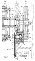
- Ein Ausführungsbeispiel der Erfindung ist in den Zeichnungen dargestellt und wird im Folgenden näher beschrieben.
- Es zeigen:
- Fig. 1
- eine schematische Darstellung eines Schnitts durch einen Teil eines Zylinder und einer damit verbundenen Einstellanordnung in einer radialen Ansicht bezüglich einer Rotationsachse des Zylinders;
- Fig. 2
- eine schematische axiale Darstellung eines Teils eines Zylinders und damit verbundener Verstellelemente.
- Eine Vorrichtung, die als Falzapparat ausgebildet ist, weist zumindest einen Zylinder 01 auf, der beispielsweise als Falzklappenzylinder 01 ausgebildet sein kann. Im Folgenden wird die Erfindung anhand eines Falzapparats beschrieben, die Erfindung lässt sich aber auch auf andere Vorrichtungen und andere Zylinder 01 übertragen, die zumindest ein während einer Rotationsbewegung des entsprechenden Zylinders 01 wahlweise und von der Drehbewegung unabhängige durchführbare Verstellbewegung von Bestandteilen des entsprechenden Zylinders 01 erfordern.
- Der Zylinder 01 weist eine Rotationsachse 02 auf, um die er rotierbar angeordnet ist. Der Zylinder 01 weist an zumindest einem bezogen auf diese Rotationsachse 02 axialen Ende einen Achszapfen 03 auf, der als Antriebswelle 03 ausgebildet ist. Dieser Achszapfen 03 ist über ein Lager 04, das beispielsweise zur einfacheren Montierbarkeit eine Lagerhülse 06 aufweisen kann, in einem Seitengestell 07 oder Kastengestell 07 des Falzapparates gelagert. Das Lager 04 kann in bekannter Weise beispielsweise Gleitlager 43 und/oder Wälzlager 43 aufweisen. Wenn im Vorangegangenen und im Folgenden von dem Seitengestell 07 die Rede ist, so ist damit immer eine Gestellwand gemeint, die auf einer gleichen Seite des Zylinders 01 angeordnet ist, wie ein im Folgenden beschriebenes Antriebszahnrad 08 des Zylinders 01. Der Achszapfen 03 reicht durch das Seitengestell 07 hindurch, so dass eine gewisse Länge des Achszapfens 03 auf einer dem Zylinder 01 abgewandten, ersten Seite SI des Seitengestells 07 herausragt. An diesem herausragenden Teil des Achszapfens 03 ist das Antriebszahnrad 08 mit einer ersten Verzahnung 09, beispielsweise einer ersten Außenverzahnung 09 drehfest angeordnet, so dass dieses Antriebszahnrad 08 ebenfalls und bevorzugt ausschließlich auf der dem Zylinder abgewandten, ersten Seite SI des Seitengestells 07 angeordnet ist. In diese erste Verzahnung 09 kann beispielsweise ein weiteres, in
Fig. 1 nicht dargestelltes, mit einem ebenfalls inFig. 1 nicht dargestellten Antriebsmotor verbundenes Zahnrad eingreifen. Auf diese oder eine andere Weise ist die Antriebswelle 03 und damit der Zylinder 01 über das Antriebszahnrad 08 antreibbar. - Der Zylinder 01 weist weiterhin zumindest ein schwenkbares und/oder rotierbares Verstellelement 11 auf. Das zumindest eine Verstellelement 11 ist um eine Achse schwenkbar und/oder rotierbar, die parallel zu der Rotationsachse 02 des Zylinders 01 liegt, aber bevorzugt exzentrisch zu dieser angeordnet ist. Das zumindest eine Verstellelement 11 kann beispielsweise als Verstellwelle 11 ausgebildet sein, die wiederum beispielsweise mit einem oder mehreren Bügeln 12 derart zusammenwirken kann, dass eine Schwenkbewegung und/oder eine Rotation der Verstellwelle 11 ein zumindest teilweises Verändern einer relativen Lage zwischen den Bügeln 12 und dem restlichen Zylinder 01 bewirkt, was wiederum eine Veränderung, beispielsweise Vergrößerung oder Verkleinerung eines effektiven Umfangs des Zylinders 01 zur Folge hat. Beispielhaft ist in
Fig. 2 zu sehen, wie ein Exzenter 13, der drehfest an einer solchen Verstellwelle 11 angeordnet ist, einen Bügel 12 in unterschiedliche Lagen relativ zu dem Zylinder 01 positionieren kann. In einer bevorzugten Ausführungsform sind mehrere derartige Verstellelemente 11 angeordnet, weiter bevorzugt symmetrisch um die Rotationsachse 02 des Zylinder 01 verteilt. Sind genannte Bügel 12 angeordnet, so sind bevorzugt in axialer Richtung bezogen auf den Zylinder 01 mehrerer Bügel 12 hintereinander angeordnet, um eine Umfangsverstellung auf einer gewünschten Länge bezogen auf die axiale Richtung vornehmen zu können. Solche in axialer Richtung bezogen auf den Zylinder 01 angeordneten mehreren Bügel 12 können auch miteinander verbunden, insbesondere als zumindest oder genau ein kammartiges Bauteil ausgebildet sein. - Das zumindest eine Verstellelement 11 weist zumindest ein Zahnrad 14 auf, das im Folgenden als Verstellwellenrad 14 bezeichnet wird. Das Verstellwellenrad 14 weist eine Verzahnung 16, beispielsweise eine Außenverzahnung 16 auf, die mit einer Verzahnung 17, beispielsweise einer Außenverzahnung 17 eines Verstellantriebsrads 18 zusammenwirkend angeordnet ist. Das Verstellantriebsrad 18 ist um die Rotationsachse 02 des Zylinder 01 rotierbar angeordnet und ist derart gelagert, dass es unabhängig von einer möglichen Rotation des Zylinders 01 und seines Achszapfens 03 rotierbar ist. Das Verstellantriebsrad 18 weist eine zentrale Öffnung auf, durch die der Achszapfen 03 des Zylinder 01 geführt ist. Weiterhin zeichnet sich das Verstellantriebsrad 18 dadurch aus, dass es zwischen dem Zylinder 01 und dem Seitengestell 07 angeordnet ist, also insbesondere auf der dem Antriebszahnrad 08 abgewandten, zweiten Seite SII des Seitengestells 07. Das Verstellantriebsrad 18 ist mit einem hülsenförmigen Stirnrad 19 drehfest verbunden, das einerseits über Lager 21 gegen den Achszapfen 03 und, zumindest in einer Ausführungsform, andererseits über Lager gegen das Seitengestell 07 abgestützt ist. Ein Teilraum 22 eines später näher beschriebenen Ölraums 42 ist über eine entsprechende Dichtung, beispielsweise einen Wellendichtring, gegenüber einem äußeren Bereich abgedichtet. Das hülsenförmige Stirnrad 19 ist bevorzugt unabhängig von dem dem Achszapfen 03 zugeordneten Lager 04 rotierbar ausgebildet.
- Ein Teil des hülsenförmigen Stirnrads 19 ragt bis auf die erste, dem Zylinder 01 abgewandte Seite SI des Seitengestells 07 und weist eine Verzahnung 23, beispielsweise Außenverzahnung 23 auf. Diese Verzahnung 23 wirkt mit einer Verzahnung 24, beispielsweise Außenverzahnung 24 eines ersten Getriebes 26 zusammen. Dieses zumindest eine erste Getriebe 26 ist als zumindest ein Drehzahlüberlagerungsgetriebe 26 ausgebildet. Ein Drehzahlüberlagerungsgetriebe 26 kann beispielsweise als Harmonic Drive Getriebe 26 oder als Planetengetriebe 26 ausgebildet sein und weist einen ersten Eingangsstrang oder Getriebeeingang und einen zweiten Eingangsstrang oder Getriebeeingang und einen Ausgangsstrang oder Getriebeausgang auf. In diesem Fall wirkt ein Antrieb des Zylinders 01 mit dem ersten Eingangsstrang zusammen und/oder ist als Teil des ersten Eingangsstrangs ausgebildet und wirkt ein Verstellantrieb mit dem zweiten Eingangsstrang zusammen oder ist als Teil des zweiten Eingangsstrangs ausgebildet. Der Verstellantrieb 36 ist bevorzugt als Verstellantriebsmotor 36 ausgebildet, beispielsweise als Elektromotor 36 oder Hydraulikzylinder 36. Der Verstellantrieb 36 kann aber beispielsweise auch als Handrad 36 ausgebildet sein. Eine bevorzugt in dem zumindest einen ersten Getriebe 26 vorhandene Grundübersetzung wird bevorzugt durch entsprechende Gestaltung von mit dem zumindest einen ersten Getriebe 26 verbundenen Bauteilen, beispielsweise durch angepasste Verzahnungen ausgeglichen. Beispielhaft wird weiter unten ein Ausführungsbeispiel beschrieben, das ein Harmonic Drive Getriebe 26 aufweist. Analog lassen sich aber alle dazu nicht im Widerspruch stehenden Merkmale auf ein Ausführungsbeispiel übertragen, das ein Planetengetriebe 26 aufweist.
- Das Antriebszahnrad 08 weist bevorzugt eine zweite Verzahnung 27, beispielsweise zweite Außenverzahnung 27 auf. Es ist natürlich auch möglich, dass die zweite Verzahnung 27 Teil eines weiteren Zahnrades ist, das drehfest mit dem Antriebszahnrad 08 verbunden ist. In einer Ausführungsform sind die erste Verzahnung 09 und die zweite Verzahnung 27 des Antriebszahnrads 08 identisch. Die zweite Verzahnung 27 des Antriebszahnrads 08 ist mit einer weiteren Verzahnung 28, beispielsweise Außenverzahnung 28 des zumindest einen ersten Getriebes 26 zusammenwirkend ausgebildet.
- Das zumindest eine erste Getriebe 26 ist so einstellbar, dass in einem ersten Betriebszustand das Antriebszahnrad 08 und das Verstellantriebsrad 18 mit einer gleichen Winkelgeschwindigkeit in einer gleichen Rotationsrichtung rotierbar und/oder rotierend angeordnet sind. Auf diese Weise kann der Zylinder 01 um seine Rotationsachse 02 rotieren, ohne dass das zumindest eine Verstellelement 11 relativ zum Zylinder 01 rotiert oder geschwenkt wird. Das zumindest eine Verstellelement 11 ist also in dem ersten Betriebszustand starr relativ zum Zylinder 01 angeordnet. Dadurch wird beispielsweise ein Umfang des Zylinders 01 konstant gehalten. Bevorzugt steht in dem ersten Betriebszustand der zweite Eingangsstrang des zumindest einen ersten Getriebes 26 und weiter bevorzugt der Verstellantrieb 36 still.
- Das zumindest eine erste Getriebe 26 ist so einstellbar, dass in einem zweiten Betriebszustand das Antriebszahnrad 08 und das Verstellantriebsrad 18 mit unterschiedlichen Winkelgeschwindigkeiten und/oder in unterschiedlichen Rotationsrichtungen rotierbar und/oder rotierend angeordnet sind. Auf diese Weise kann der Zylinder 01 um seine Rotationsachse 02 rotieren oder stillstehen, während gleichzeitig das zumindest eine Verstellelement 11 relativ zum Zylinder 01 rotiert oder geschwenkt wird. Das zumindest eine Verstellelement 11 wird also in dem zweiten Betriebszustand relativ zum Zylinder 01 rotiert oder geschwenkt. Dadurch wird beispielsweise ein Umfang des Zylinders 01 wie oben beschrieben mittels Bügeln 12 vergrößert oder verkleinert. Bevorzugt wird in dem zweiten Betriebszustand der zweite Eingangsstrang und weiter bevorzugt der Verstellantrieb 36 bewegt, insbesondere rotiert.
- Das zumindest eine erste Getriebe 26 ist bevorzugt als Harmonic Drive Getriebe 26 ausgebildet und weist in diesem Fall zumindest folgende Bestandteile auf: Eine Welle 29, eine flexible Innenhülse 31, ein Lager 32, das zwischen Welle 29 und flexibler Innenhülse 31 angeordnet ist und zwei Außenhülsen 33; 34 (auch Circular Splines 33; 34 genannt), von denen eine als Antriebsaußenhülse 33 und eine als Verstellantriebsaußenhülse 34 ausgebildet ist. Die Antriebsaußenhülse 33 ist rotierbar gelagert und weist die bereits erwähnte Verzahnung 28 auf, die mit der beispielsweise zweiten Verzahnung 27 des Antriebszahnrads 08 zusammenwirkend angeordnet ist. Die Verstellantriebsaußenhülse 34 ist rotierbar gelagert und weist die bereits erwähnte Verzahnung 24 auf, die mit der Verzahnung 23 des hülsenförmigen Stirnrads 19 zusammenwirkend angeordnet ist. Die Welle 29 und die flexible Innenhülse 31 und bevorzugt auch das dazwischen angeordnete Lager 32 erstrecken sich über eine solche Länge, dass die Innenhülse 31 zeitgleich sowohl mit der Antriebsaußenhülse 33 als auch mit der in Längsrichtung der Welle 29 versetzt angeordneten Verstellantriebsaußenhülse 34 zusammenwirkend angeordnet ist. Die Welle 29 ist bezogen auf ihren Querschnitt im Bereich der Innenhülse 31 nicht kreisförmig, sondern bevorzugt elliptisch ausgebildet und verformt über das Lager 32 die flexible Innenhülse 31 derart, dass diese zumindest an ihrer Außenseite ebenfalls einen elliptischen Querschnitt aufweist. Eine solche flexible Innenhülse 31 wird auch als Flex Spline 31 bezeichnet. Eine solche Welle 29 wird auch als Wave Generator 29 bezeichnet. Die Welle 29, die Innenhülse 31, die Antriebsaußenhülse 33 und die Verstellantriebsaußenhülse 34 sind um eine gemeinsame Getriebeachse 46 rotierbar angeordnet.
- Die Innenhülse 31 wirkt an ihrem ersten axialen Ende mit der Antriebsaußenhülse 33 zusammen, indem die Innenhülse 31 eine erste Außenverzahnung mit einer ersten Anzahl von Zähnen aufweist, die mit einer Innenverzahnung der Antriebsaußenhülse 33 verzahnt ist, die eine zweite Anzahl von Zähnen aufweist. Durch die elliptische Verformung der flexiblen Innenhülse 31 und das Lager 32 ist gewährleistet, dass je nach Drehlage von flexibler Innenhülse 31 und Antriebsaußenhülse 33 zueinander zumindest zwei andere, sich jeweils gegenüberliegende Zähne der ersten Außenverzahnung der Innenhülse 31 mit der Innenverzahnung der Antriebsaußenhülse 33 in verzahntem Kontakt stehen.
- Die Innenhülse 31 wirkt an ihrem zweiten axialen Ende mit der Verstellantriebsaußenhülse 34 zusammen, indem die Innenhülse 32 eine zweite Außenverzahnung mit einer dritten Anzahl von Zähnen aufweist, die mit einer Innenverzahnung der Verstellantriebsaußenhülse 34 verzahnt ist, das eine vierte Anzahl von Zähnen aufweist. Durch die elliptische Verformung der flexiblen Innenhülse 31 und das Lager 32 ist gewährleistet, dass je nach Drehlage von flexibler Innenhülse 31 und Verstallantriebsaußenhülse 34 zueinander zumindest zwei andere, sich jeweils gegenüberliegende Zähne der zweiten Außenverzahnung der Innenhülse 31 mit der Innenverzahnung der Verstellantriebsaußenhülse 34 in Kontakt stehen.
- Die flexible Innenhülse 31 stellt ein Drehmoment übertragendes und/oder übertragfähiges Zentralbauteil dar. Ein als Bestandteil des ersten Eingangsstrangs ausgebildetes, erste Bauteil des zumindest einen Getriebes 26, beispielsweise die Antriebsaußenhülse 33, und ein als Bestandteil des Ausgangsstrangs ausgebildetes, zweites Bauteil des zumindest einen Getriebes 26, beispielsweise die Verstellantriebsaußenhülse 34, und ein als Bestandteil des zweiten Eingangsstrangs ausgebildetes, drittes Bauteil des zumindest einen Getriebes 26, beispielsweise die Welle 29, stehen jeweils direkt und/oder über zumindest ein zwischengeschaltetes Lager mit dem gemeinsamen, Drehmoment übertragenden und/oder übertragfähigen Zentralbauteil in Kontakt. Das Zentralbauteil zeichnet sich insbesondere dadurch aus, dass es zwangsläufig bewegt wird, sobald Bestandteile des ersten und/oder des zweiten Eingangsstrangs und/oder des Ausgangsstrangs bewegt werden, während Bestandteile des ersten Eingangsstrangs oder der zweiten Eingangsstrangs oder des Ausgangsstrangs still stehen können.
- Die erste Anzahl von Zähnen und die dritte Anzahl von Zähnen können unterschiedlich sein, sind aber bevorzugt gleich. Die Verhältnisse von erster zu zweiter und von dritter zu vierter Anzahl von Zähnen, sowie die tatsächliche erste, zweite, dritte und vierte Anzahl von Zähnen sind so aufeinander abgestimmt, dass bei feststehender Welle 29 eine Rotation des Antriebszahnrads 08 über die Antriebsaußenhülse 33, die flexible Innenhülse 31 und die Verstellantriebsaußenhülse 34 auf das hülsenförmige Stirnrad 19 und das Verstellantriebsrad 18 derart übertragen wird, dass der erste Betriebszustand gegeben ist, dass also Antriebszahnrad 08 und Verstellantriebsrad 18 mit gleicher Winkelgeschwindigkeit und gleicher Rotationsrichtung rotieren.
- Wird dagegen die Welle 29 um ihre Längsachse gedreht, beispielsweise rotiert oder geschwenkt, so überträgt sich nicht nur die Rotation des Antriebszahnrades 08, sondern auch diese Drehbewegung der Welle 29 auf die Verstellantriebsaußenhülse 34 und damit auf das Verstellantriebsrad 18. Je nach Drehsinn der Welle 29 wird dadurch eine Winkelgeschwindigkeit des Verstellantriebsrads 18 größer oder kleiner als eine Winkelgeschwindigkeit des Antriebszahnrads 08. (Prinzipiell ist sogar eine entgegen gesetzte Rotationsrichtung möglich.) Dadurch ergibt sich eine relative Rotation von Zylinder 01 und Verstellelement 11, was beispielsweise für eine gewünschte Verstellbewegung der Verstellelemente 11 ausgenutzt werden kann. Die Verstellbewegung der Verstellelemente 11 ist dabei unabhängig davon möglich, ob der Zylinder 01 sich in einem rotierenden oder einem stillstehenden Zustand befindet.
- Die Welle 29 ist in einer Drehmoment übertragenden oder eine Drehmomentübertragung ermöglichenden Weise mit dem Verstellantrieb 36 verbunden, beispielsweise über ein zweites Getriebe 44, das weitere, insbesondere vierte Bauteile 37; 38 aufweist wie beispielsweise zumindest ein Zahnrad 37 und/oder zumindest ein Zugmittel 38, das als Riemen 38, beispielsweise Zahnriemen 38 oder als Kette 38 ausgebildet sein kann. Eine Aktivierung des Verstellantriebs 36, d. h. insbesondere eine Rotation einer Welle des Verstellantriebsmotors 36 bewirkt dann die oben beschriebene, von der Rotation des Zylinders 01 unabhängig Verstellbewegung des zumindest einen Verstellelements 11.
- In einer bevorzugten Ausführungsform steht der Verstellantrieb 36 im ersten Betriebszustand still und ist der Verstellantrieb 36 im zweiten Betriebszustand zumindest teilweise rotierend angeordnet, d. h. dass zumindest eine Welle des Verstellantriebs 36 im zweiten Betriebszustand rotierend angeordnet ist.
- In einer besonders Platz sparenden Ausführungsform durchdringt die Welle 29 das Seitengestell 07 und ist zumindest ein Teil des zweiten Getriebes 44, beispielsweise zumindest ein Zahnrad 37 und/oder zumindest ein Zugmittel 38 auf der dem Zylinder 01 zugewandten zweiten Seite SII des Seitengestells 07 angeordnet. In einer ebenfalls Platz sparenden Weiterbildung ist der Verstellantrieb 36 wiederum auf der ersten, dem Zylinder 01 abgewandten Seite SI des Seitengestells 07 angeordnet. Dazu ist zumindest ein Teil des Verstellantrieb 36 oder eine damit verbundene Welle in einer das Seitengestell 07 durchdringenden Weise angeordnet.
- Das zumindest eine erste Getriebe 26 und das Antriebszahnrad 08 sind bevorzugt auf der gleichen, ersten Seite SI des Seitengestells 07 angeordnet. Weiterhin ist das zumindest eine erste Getriebe 26 bevorzugt direkt mit dem Antriebszahnrad 08 zusammenwirkend ausgebildet. Das bedeutet, dass eine drehfest zu dem Antriebszahnrad 08 angeordnete zweite Verzahnung 27 mit einer Verzahnung 28 des zumindest einen ersten Getriebes 26 zusammenwirkend ausgebildet ist. Es ist auch möglich, an dieser Stelle noch weitere Zahnräder vorzusehen, insbesondere in einer zwischengeschalteten Weise, beispielsweise für angepasste Übersetzungsverhältnisse.
- Von dem Seitengestell 07 ausgehend weist bevorzugt zumindest ein Vorsprung 39, beispielsweise eine Rippe 39, auf die dem Zylinder 01 abgewandte, erste Seite SI des Seitengestells 07. An diesem Vorsprung 39 ist eine Abdeckung 41 angeordnet und beispielsweise mittels Schrauben oder ähnlichem lösbar befestigt. Die Abdeckung erstreckt sich bevorzugt zumindest im Wesentlichen parallel zu dem Seitengestell 07. Der zumindest eine Vorsprung 39, die Abdeckung 41 und Teile des Seitengestells 07 bilden ein abgeschlossenes Volumen 42. Das abgeschlossene Volumen 42 kann alternativ oder zusätzlich von anderen Bauteilen begrenzt werden. Das abgeschlossene Volumen 42 ist als gemeinsamer Ölraum 42 ausgebildet. Dieser gemeinsame Ölraum 42 dient zugleich als Ölraum 42 des Antriebszahnrades 08 und als Ölraum 42 des zumindest einen ersten Getriebes 26 und bevorzugt auch jeglicher rotierbarer Verbindungen zwischen Antriebszahnrad 08 und erstem Getriebe 26. Der Ölraum 42 dient in bekannter Weise dazu, mittels nicht dargestellter Vorrichtungen wie Pumpen, Leitungen, Düsen, Öffnungen, Auffangvorrichtungen etc. für eine angemessene Ölversorgung von im Ölraum 42 angeordneten Vorrichtungen zu sorgen. Der gemeinsame Ölraum 42 kann auch durch andere Vorrichtungen als zuvor beschrieben zu einer Umgebung hin abgegrenzt werden. Der gemeinsame Ölraum 42 ist insbesondere an Einlassöffnungen, Auslassöffnungen und einer durch den Achszapfen 03 des Zylinders 01 bedingten Öffnung mittels bekannter Mittel und Vorrichtungen abgedichtet. Auch eine Öffnung, die für die Durchführung der Welle 29 durch das Seitengestell 07 notwendig ist, ist entsprechend abgedichtet. Zu diesem Zweck ist der Querschnitt der Welle 29 zumindest in diesem Bereich bevorzugt kreisförmig ausgebildet. Das zweite Getriebe 44 und insbesondere das weitere Bauteil 37; 38, beispielsweise Zahnrad 37 und/oder Zugmittel 38 ist bevorzugt außerhalb des gemeinsamen Ölraums 42 und weiter bevorzugt auf der dem Zylinder 01 zugewandten, zweiten Seite SII des Seitengestells 07 angeordnet.
- Im Fall eines als Harmonic Drive Getriebe 26 ausgebildeten ersten Getriebes 26 ist die Antriebsaußenhülse 33 ist als das als Bestandteil des ersten Eingangsstrangs ausgebildete, erste Bauteil des zumindest einen Getriebes 26 ausgebildet und ist die Verstellantriebsaußenhülse 34 als das als Bestandteil des Ausgangsstrangs ausgebildete, zweite Bauteil des zumindest einen Getriebes 26 ausgebildet und ist die Welle 29 ein als Bestandteil des zweiten Eingangsstrangs ausgebildetes, drittes Bauteil des zumindest einen Getriebes 26 ausgebildet. Die Antriebsaußenhülse 33, die Verstellantriebsaußenhülse 34 und das Antriebszahnrad 08 sind in dem gemeinsamen Ölraum 42 angeordnet. Bevorzugt ist zusätzlich die flexible Innenhülse 31 in dem gemeinsamen Ölraum 42 angeordnet. Weiter bevorzugt ist zusätzlich die Welle 29 zumindest teilweise in dem gemeinsamen Ölraum 42 angeordnet. Erfindungsgemäß sind damit das Antriebszahnrad 08, zumindest ein, als Bestandteil des ersten Eingangsstrangs ausgebildetes, erstes Bauteil und zumindest ein, als Bestandteil des Ausgangsstrangs ausgebildetes, zweites Bauteil des zumindest einen Getriebes 26 und bevorzugt zumindest teilweise auch ein, als Bestandteil des zweiten Eingangsstrangs ausgebildetes, drittes Bauteil des zumindest einen Getriebes 26 in dem gemeinsamen Ölraum 42 angeordnet.
- Im Fall eines als Planetengetriebe 26 ausgebildeten ersten Getriebes 26 sind ein Sonnenrad, ein zumindest ein Planetenrad rotierbar tragender Planetenradträger und ein Hohlrad in beliebiger Zuordnung als als Bestandteil des ersten Eingangsstrangs ausgebildetes, erstes Bauteil und als als Bestandteil des Ausgangsstrangs ausgebildetes, zweites Bauteil und als als Bestandteil des zweiten Eingangsstrangs ausgebildetes, drittes Bauteil des zumindest einen Getriebes 26 ausgebildet. Das Hohlrad weist dabei eine gleiche Rotationsachse auf, wie das Sonnenrad. Das zumindest eine Planetenrad steht sowohl mit dem Sonnenrad als auch mit dem Hohlrad in verzahntem Eingriff und ist über zumindest ein Lager relativ zu dem Planetenradträger rotierbar gelagert. Das Sonnenrad, das Hohlrad und der Planetenradträger mit dem zumindest einen Planetenrad sind im Fall eines Planetengetriebes genauso in dem gemeinsamen Ölraum 42 angeordnet, wie das Antriebszahnrad 08. Erfindungsgemäß sind damit das Antriebszahnrad 08, zumindest ein, als Bestandteil des ersten Eingangsstrangs ausgebildetes, erstes Bauteil und zumindest ein, als Bestandteil des Ausgangsstrangs ausgebildetes, zweites Bauteil des zumindest einen Getriebes 26 und bevorzugt zumindest teilweise auch ein, als Bestandteil des zweiten Eingangsstrangs ausgebildetes, drittes Bauteil des zumindest einen Getriebes 26 in dem gemeinsamen Ölraum 42 angeordnet. Das Sonnenrad, das Hohlrad und der Planetenträger sind um die gemeinsame Getriebeachse 46 rotierbar angeordnet.
- In diesem Fall eines Planetengetriebes stellt das zumindest eine Planetenrad ein Drehmoment übertragendes und/oder übertragfähiges Zentralbauteil dar. Ein als Bestandteil des ersten Eingangsstrangs ausgebildetes, erste Bauteil des zumindest einen Getriebes 26, beispielsweise der Planetenträger, und ein als Bestandteil des Ausgangsstrangs ausgebildetes, zweites Bauteil des zumindest einen Getriebes 26, beispielsweise das Sonnenrad, und ein als Bestandteil des zweiten Eingangsstrangs ausgebildetes, drittes Bauteil des zumindest einen Getriebes 26, beispielsweise das Hohlrad, stehen jeweils direkt und/oder über zumindest ein zwischengeschaltetes Lager mit dem gemeinsamen, Drehmoment übertragenden und/oder übertragfähigen Zentralbauteil in Kontakt. Das Zentralbauteil zeichnet sich auch in diesem Fall insbesondere dadurch aus, dass es zwangsläufig bewegt wird, sobald Bestandteile des ersten und/oder des zweiten Eingangsstrangs und/oder des Ausgangsstrangs bewegt werden, während Bestandteile des ersten Eingangsstrangs oder der zweiten Eingangsstrangs oder des Ausgangsstrangs still stehen können.
- Da das Seitengestell 07 nicht zwangsläufig an allen Stellen eine gleiche Dicke, also Ausdehnung in axialer Richtung bezüglich des Zylinders 01 aufweist, ist unter eine Anordnung eines Bauteils auf einer Seite des Seitengestells 07 allgemein eine solche Anordnung zu verstehen, bei der das Bauteil auf dieser Seite relativ zu dem in axialer Richtung benachbarten Bereich des Seitengestells 07 angeordnet ist.
- Es ergibt sich als die Einstellanordnung des zumindest einen Zylinders 01 des Falzapparats, wobei der zumindest eine Zylinder 01 um die Rotationsachse 02 rotierbar und/oder rotierend angeordnet ist und auf die axiale Richtung bezogen zumindest an einem Ende einen drehfest mit dem zumindest einen Zylinder 01 verbundenen Achszapfen 03 aufweist und wobei das zumindest eine Antriebszahnrad 08 mit dem Achszapfen 03 drehfest verbunden ist und wobei das zumindest eine Verstellantriebsrad 18 relativ zu dem zumindest einen Zylinder 01 um die Rotationsachse 02 des zumindest einen Zylinders 01 rotierbar und/oder rotierend angeordnet ist und wobei das zumindest eine Antriebszahnrad 08 über das zumindest eine, als Drehzahlüberlagerungsgetriebe 26 ausgebildete erste Getriebe 26 mit dem zumindest einen Verstellantriebsrad 18 und mit dem Verstellantrieb 36 verbunden ist, wobei das zumindest eine erste Getriebe 26 zumindest den ersten Eingangsstrang und den zweiten Eingangsstrang und den Ausgangsstrang aufweist und wobei der Falzapparat den gemeinsamen Ölraum 42 aufweist, in dem zumindest das Antriebszahnrad 08 vollständig und zumindest ein, als Bestandteil des ersten Eingangsstrangs ausgebildetes, erstes Bauteil des zumindest einen ersten Getriebes 26 und zumindest ein, als Bestandteil des Ausgangsstrangs ausgebildetes, zweites Bauteil des zumindest einen ersten Getriebes 26 angeordnet sind.
- In einer bevorzugten Ausführungsform zeichnet sich die Einstellanordnung dadurch aus, dass das zumindest eine erste Getriebe 26 auf der gleichen ersten Seite SI des Seitengestells 07 des Falzapparats angeordnet ist, wie das Antriebszahnrad 08 und weiter bevorzugt, dass die erste Seite SI eine dem zumindest einen Zylinder 01 abgewandte Seite SI des Seitengestells 07 ist.
- In einer bevorzugten Ausführungsform zeichnet sich die Einstellanordnung dadurch aus, dass das zumindest eine erste Getriebe 26 auf der ersten Seite SI des Seitengestells 07 des Falzapparats angeordnet ist und dass die Welle 29 des zumindest einen ersten Getriebes 26 mit einem auf der zweiten Seite SII des Seitengestell 07 angeordneten Bauteil 37; 38, beispielsweise einem Zahnrad 37 und/oder einem Zugmittel 38 eines zweiten Getriebes 44 der Einstellanordnung formschlüssig und/oder reibschlüssig in Verbindung stehend angeordnet ist.
- In einer bevorzugten Ausführungsform zeichnet sich die Einstellanordnung dadurch aus, dass der Verstellantrieb 36 auf der gleichen ersten Seite SI des Seitengestells 07 des Falzapparats angeordnet ist wie das Antriebszahnrad 08 und/oder das zumindest eine erste Getriebe 26.
- In einer bevorzugten Ausführungsform zeichnet sich die Einstellanordnung dadurch aus, dass das Antriebszahnrad 08 mit einem um eine Getriebeachse 46 rotierbaren Bauteil des zumindest einen ersten Getriebes 26 in Kontakt steht. Bevorzugt ist dieses Bauteil ein, als Bestandteil des ersten Eingangsstrangs ausgebildetes, erstes Bauteil des zumindest einen ersten Getriebes 26.
- In einer bevorzugten Ausführungsform zeichnet sich die Einstellanordnung dadurch aus, dass sämtliche, überhaupt in einem Ölraum 42 angeordneten Bauteile des zumindest einen ersten Getriebes 26 zusammen mit dem Antriebszahnrad 08 in dem gemeinsamen Ölraum 42 angeordnet sind. Anders ausgedrückt bedeutet das, dass genau ein Ölraum 42 angeordnet ist, in dem überhaupt Bauteile des zumindest einen ersten Getriebes 26 angeordnet sind und dass dies der gemeinsame Ölraum 42 ist, in dem auch das Antriebszahnrad 08 angeordnet ist. Anders ausgedrückt bedeutet das, dass kein Bauteil des zumindest einen ersten Getriebes 26 in einem anderen als dem gemeinsamen Ölraum 42 Angeordnet ist.
-
- 01
- Zylinder, Falzklappenzylinder
- 02
- Rotationsachse (01)
- 03
- Achszapfen, Antriebswelle
- 04
- Lager
- 05
- -
- 06
- Lagerhülse
- 07
- Seitengestell, Kastengestell
- 08
- Antriebszahnrad
- 09
- Verzahnung, Außenverzahnung (08), erste
- 10
- -
- 11
- Verstellelement, Verstellwelle
- 12
- Bügel
- 13
- Exzenter
- 14
- Zahnrad, Verstellwellenrad (11)
- 15
- -
- 16
- Verzahnung, Außenverzahnung (14)
- 17
- Verzahnung, Außenverzahnung (18)
- 18
- Verstellantriebsrad
- 19
- Stirnrad
- 20
- -
- 21
- Lager (19)
- 22
- Teilraum (42)
- 23
- Verzahnung, Außenverzahnung (19)
- 24
- Verzahnung, Außenverzahnung (26)
- 25
- -
- 26
- Getriebe, Drehzahlüberlagerungsgetriebe, Harmonic Drive Getriebe, Planetengetriebe, erstes
- 27
- Verzahnung, Außenverzahnung (08), zweite
- 28
- Verzahnung, Außenverzahnung (26)
- 29
- Welle, Wave Generator (26)
- 30
- -
- 31
- Innenhülse, Flex Spline (26)
- 32
- Lager(29; 31)
- 33
- Außenhülse, Circular Spline, Antriebsaußenhülse (26)
- 34
- Außenhülse, Circular Spline, Verstellantriebsaußenhülse (26)
- 35
- -
- 36
- Verstellantrieb, Handrad, Verstellantriebsmotor, Elektromotor, Hydraulikzylinder
- 37
- Bauteil, Zahnrad
- 38
- Bauteil, Zugmittel, Riemen, Zahnriemen, Kette
- 39
- Vorsprung, Rippe
- 40
- -
- 41
- Abdeckung
- 42
- Volumen, Ölraum
- 43
- Gleitlager, Wälzlager
- 44
- Getriebe, zweites
- 45
- -
- 46
- Getriebeachse (26)
- SI
- Seite (07), erste
- SII
- Seite (07), zweite
Claims (15)
- Einstellanordnung zumindest eines Zylinders (01) eines Falzapparats, wobei der zumindest eine Zylinder (01) um eine Rotationsachse (02) rotierbar und/oder rotierend angeordnet ist und auf eine axiale Richtung bezogen zumindest an einem Ende einen drehfest mit dem zumindest einen Zylinder (01) verbundenen Achszapfen (03) aufweist und wobei zumindest ein Antriebszahnrad (08) mit dem Achszapfen (03) drehfest verbunden ist und wobei zumindest ein Verstellantriebsrad (18) relativ zu dem zumindest einen Zylinder (01) um die Rotationsachse (02) des zumindest einen Zylinders (01) rotierbar und/oder rotierend angeordnet ist und wobei das zumindest eine Antriebszahnrad (08) zumindest über ein als Drehzahlüberlagerungsgetriebe (26) ausgebildetes Getriebe (26) mit dem zumindest einen Verstellantriebsrad (18) und mit einem Verstellantrieb (36) verbunden ist, wobei das zumindest eine Getriebe (26) zumindest einen ersten Eingangsstrang und einen zweiten Eingangsstrang und einen Ausgangsstrang aufweist, dadurch gekennzeichnet, dass der Falzapparat einen gemeinsamen Ölraum (42) aufweist, in dem zumindest das Antriebszahnrad (08) vollständig und zumindest ein, als Bestandteil des ersten Eingangsstrangs ausgebildetes, erstes Bauteil des zumindest einen Getriebes (26) und zumindest ein, als Bestandteil des Ausgangsstrangs ausgebildetes, zweites Bauteil des zumindest einen Getriebes (26) angeordnet sind und dass das als Bestandteil des ersten Eingangsstrangs ausgebildete, erste Bauteil des zumindest einen Getriebes (26) und das als Bestandteil des Ausgangsstrangs ausgebildete, zweite Bauteil des zumindest einen Getriebes (26) als Drehmoment übertragende und/oder übertragfähige Bauteile ausgebildet sind.
- Einstellanordnung nach Anspruch 1, dadurch gekennzeichnet, dass das sämtliche zwischen dem als Bestandteil des ersten Eingangsstrangs ausgebildeten, ersten Bauteil des zumindest einen Getriebes (26) und dem als Bestandteil des Ausgangsstrangs ausgebildeten, zweiten Bauteil des zumindest einen Getriebes (26) Drehmoment übertragenden und/oder übertragfähigen Bauteile des zumindest einen Getriebes (26) in dem gemeinsamen Ölraum (42) angeordnet sind.
- Einstellanordnung nach Anspruch 1 oder 2, dadurch gekennzeichnet, dass das zumindest eine Getriebe (26) als Harmonic Drive Getriebe (26) ausgebildet ist und zumindest eine Welle (29), eine flexible Innenhülse (31), eine Antriebsaußenhülse (33) und eine Verstellantriebsaußenhülse (34) aufweist.
- Einstellanordnung nach Anspruch 3, dadurch gekennzeichnet, dass die Antriebsaußenhülse (33) das als Bestandteil des ersten Eingangsstrangs ausgebildete, erste Bauteil des zumindest einen Getriebes (26) ist und dass die Verstellantriebsaußenhülse (34) das als Bestandteil des Ausgangsstrangs ausgebildete, zweite Bauteil des zumindest einen Getriebes (26) ist.
- Einstellanordnung nach Anspruch 3, dadurch gekennzeichnet, dass die flexible Innenhülse (31) in dem gemeinsamen Ölraum (42) angeordnet ist und/oder dass die Welle (29) zumindest teilweise in dem gemeinsamen Ölraum (42) angeordnet ist.
- Einstellanordnung nach Anspruch 1, dadurch gekennzeichnet, dass der erste Eingangsstrang und der zweite Eingangsstrang und der Ausgangsstrang des zumindest einen Getriebes (26) jeweils zumindest teilweise auf einer gleichen, ersten Seite (SI) eines Seitengestells (07) des Falzapparats angeordnet sind, wie das Antriebszahnrad (08).
- Einstellanordnung nach Anspruch 6, dadurch gekennzeichnet, dass die erste Seite (SI) eine dem zumindest einen Zylinder (01) abgewandte Seite (SI) des Seitengestells (07) ist.
- Einstellanordnung nach Anspruch 1, dadurch gekennzeichnet, dass der erste Eingangsstrang und der zweite Eingangsstrang und der Ausgangsstrang des zumindest einen Getriebes (26) durch Drehmoment übertragende und/oder übertragfähige Bauteile gebildet sind.
- Einstellanordnung nach Anspruch 1, dadurch gekennzeichnet, dass der erste Eingangsstrang und der Ausgangsstrang des zumindest einen Getriebes (26) auf einer ersten Seite (SI) eines Seitengestells (07) des Falzapparats angeordnet sind und dass eine Welle (29) des zumindest einen Getriebes (26) mit einem auf einer zweiten Seite (SII) des Seitengestell (07) angeordneten weiteren Bauteil (37; 38) der Einstellanordnung formschlüssig und/oder reibschlüssig in Verbindung stehend angeordnet ist.
- Einstellanordnung nach Anspruch 9, dadurch gekennzeichnet, dass das auf der zweiten Seite (SII) des Seitengestells (07) angeordnete weitere Bauteil (37; 38) ein Zahnrad (37) oder ein Zugmittel (38) ist.
- Einstellanordnung nach Anspruch 1 oder 2, dadurch gekennzeichnet, dass der Verstellantrieb (36) auf einer gleichen ersten Seite (SI) eines Seitengestells (07) des Falzapparats angeordnet ist wie das Antriebszahnrad (08) und/oder das zumindest eine Getriebe (26).
- Einstellanordnung nach Anspruch 1, dadurch gekennzeichnet, dass jegliche rotierbare Verbindung zwischen dem Antriebszahnrad (08) und dem zumindest einen Getriebe (26) in dem gemeinsamen Ölraum (42) angeordnet ist.
- Einstellanordnung nach Anspruch 1, dadurch gekennzeichnet, dass das als Bestandteil des ersten Eingangsstrangs ausgebildete, erste Bauteil des zumindest einen Getriebes (26) und das als Bestandteil des Ausgangsstrangs ausgebildete, zweite Bauteil des zumindest einen Getriebes (26) und ein als Bestandteil des zweiten Eingangsstrangs ausgebildetes, drittes Bauteil des zumindest einen Getriebes (26) jeweils direkt und/oder über zumindest ein zwischengeschaltetes Lager mit zumindest einem gemeinsamen, Drehmoment übertragenden und/oder übertragfähigen Zentralbauteil in Kontakt stehen.
- Einstellanordnung nach Anspruch 13, dadurch gekennzeichnet, dass das zumindest eine Zentralbauteil ebenfalls in dem gemeinsamen Ölraum (42) angeordnet ist.
- Einstellanordnung nach Anspruch 3 und Anspruch 13, dadurch gekennzeichnet, dass die flexible Innenhülse (31) als das Zentralbauteil ausgebildet ist.
Applications Claiming Priority (2)
| Application Number | Priority Date | Filing Date | Title |
|---|---|---|---|
| DE201010041457 DE102010041457B3 (de) | 2010-09-27 | 2010-09-27 | Einstellanordnung eines Zylinders eines Falzapparats |
| PCT/EP2011/056033 WO2012041537A1 (de) | 2010-09-27 | 2011-04-15 | Einstellanordnung eines zylinders eines falzapparats |
Publications (2)
| Publication Number | Publication Date |
|---|---|
| EP2550163A1 EP2550163A1 (de) | 2013-01-30 |
| EP2550163B1 true EP2550163B1 (de) | 2016-08-10 |
Family
ID=43983722
Family Applications (1)
| Application Number | Title | Priority Date | Filing Date |
|---|---|---|---|
| EP11715505.1A Active EP2550163B1 (de) | 2010-09-27 | 2011-04-15 | Einstellanordnung eines zylinders eines falzapparats |
Country Status (4)
| Country | Link |
|---|---|
| EP (1) | EP2550163B1 (de) |
| CN (1) | CN102858538B (de) |
| DE (1) | DE102010041457B3 (de) |
| WO (1) | WO2012041537A1 (de) |
Families Citing this family (1)
| Publication number | Priority date | Publication date | Assignee | Title |
|---|---|---|---|---|
| CN106379036B (zh) * | 2016-08-25 | 2018-05-18 | 高斯图文印刷系统(中国)有限公司 | 一种胶、柔混合印刷机的轴向调整机构 |
Family Cites Families (5)
| Publication number | Priority date | Publication date | Assignee | Title |
|---|---|---|---|---|
| DE4103160C2 (de) * | 1991-02-02 | 1994-09-08 | Roland Man Druckmasch | Falzapparat mit einem verstellbare Elemente, insbesondere Falzklappen oder bogenförmige Segmente, aufweisenden Falzwerkzylinder |
| DE4225810C2 (de) * | 1992-08-05 | 1995-06-14 | Roland Man Druckmasch | Falzzylinder |
| DE19625083C1 (de) * | 1996-06-22 | 1997-11-13 | Koenig & Bauer Albert Ag | Getriebe |
| DE10148503C5 (de) * | 2001-10-01 | 2008-01-31 | Koenig & Bauer Aktiengesellschaft | Falzapparat mit umfangsverstellbarem Zylinder |
| DE102005036612B4 (de) * | 2005-08-01 | 2007-04-05 | Man Roland Druckmaschinen Ag | Falztrommel eines Falzapparats einer Druckmaschine |
-
2010
- 2010-09-27 DE DE201010041457 patent/DE102010041457B3/de not_active Expired - Fee Related
-
2011
- 2011-04-15 WO PCT/EP2011/056033 patent/WO2012041537A1/de not_active Ceased
- 2011-04-15 CN CN201180020883.7A patent/CN102858538B/zh not_active Expired - Fee Related
- 2011-04-15 EP EP11715505.1A patent/EP2550163B1/de active Active
Also Published As
| Publication number | Publication date |
|---|---|
| WO2012041537A1 (de) | 2012-04-05 |
| EP2550163A1 (de) | 2013-01-30 |
| DE102010041457B3 (de) | 2011-12-01 |
| CN102858538B (zh) | 2014-12-03 |
| CN102858538A (zh) | 2013-01-02 |
Similar Documents
| Publication | Publication Date | Title |
|---|---|---|
| DE102008032665B4 (de) | Vorrichtung und Verfahren zur Veränderung des Verdichtungsverhältnisses einer Brennkraftmaschine | |
| DE3006331C2 (de) | Getriebe | |
| EP3612402B1 (de) | Getriebe für ein kraftfahrzeug, insbesondere für ein seriell/paralleles hybridfahrzeug | |
| DE4426987C2 (de) | Falzapparat mit Formatumstellung | |
| DE102013002310A1 (de) | Leistungsübertragungsvorrichtung | |
| EP1523610A1 (de) | Vorrichtung zur veränderung der steuerzeiten einer brennkraftmaschine | |
| WO2016142446A1 (de) | Getriebeanordnung und elektroantrieb mit einer solchen getriebeanordnung | |
| EP3505907B1 (de) | Prüfvorrichtung | |
| EP2616644B1 (de) | Vorrichtung zur phasenverschiebung des drehwinkels eines antriebsrades zu einem abtriebsrad | |
| DE10148503B4 (de) | Falzapparat mit umfangsverstellbarem Zylinder | |
| DE10149255A1 (de) | Wellgetriebe mit Planetenradantrieb | |
| DE102010041457B3 (de) | Einstellanordnung eines Zylinders eines Falzapparats | |
| DE102008039543B4 (de) | Rollenmühle | |
| EP1918236A2 (de) | Sammelzylinder eines Falzapparats einer Druckmaschine | |
| EP1372962B1 (de) | Antrieb eines druckwerks | |
| EP3809015A1 (de) | Wellgetriebe mit zahnriemen | |
| DE102008039926A1 (de) | Differentialgetriebeeinheit | |
| WO2021023338A1 (de) | Kompakte getriebeanordnung mit stufenplanetensatz und stirnraddifferential | |
| EP3441613B1 (de) | Hydrostatische zahnrad-kreiskolbenmaschine | |
| DE102018130497B4 (de) | Planetenbaugruppe sowie Getriebeanordnung mit der Planetenbaugruppe | |
| DE10160101C1 (de) | Räderfalzapparat | |
| DE102006061463A1 (de) | Vorrichtung zum variablen Antreiben einer Hohlwelle mit einer innenliegenden Spindel | |
| DE3327772A1 (de) | Verdraengermaschine, insbesondere zykloiden-planetengetriebe mit integriertem hydraulischem motor | |
| AT505628B1 (de) | Getriebe zur umkehrspielfreien kraftübertragung | |
| DE3614803A1 (de) | Getriebe zum antrieb der walzen einer walzstrasse |
Legal Events
| Date | Code | Title | Description |
|---|---|---|---|
| PUAI | Public reference made under article 153(3) epc to a published international application that has entered the european phase |
Free format text: ORIGINAL CODE: 0009012 |
|
| 17P | Request for examination filed |
Effective date: 20121023 |
|
| AK | Designated contracting states |
Kind code of ref document: A1 Designated state(s): AL AT BE BG CH CY CZ DE DK EE ES FI FR GB GR HR HU IE IS IT LI LT LU LV MC MK MT NL NO PL PT RO RS SE SI SK SM TR |
|
| DAX | Request for extension of the european patent (deleted) | ||
| GRAP | Despatch of communication of intention to grant a patent |
Free format text: ORIGINAL CODE: EPIDOSNIGR1 |
|
| INTG | Intention to grant announced |
Effective date: 20160318 |
|
| GRAS | Grant fee paid |
Free format text: ORIGINAL CODE: EPIDOSNIGR3 |
|
| GRAA | (expected) grant |
Free format text: ORIGINAL CODE: 0009210 |
|
| AK | Designated contracting states |
Kind code of ref document: B1 Designated state(s): AL AT BE BG CH CY CZ DE DK EE ES FI FR GB GR HR HU IE IS IT LI LT LU LV MC MK MT NL NO PL PT RO RS SE SI SK SM TR |
|
| REG | Reference to a national code |
Ref country code: GB Ref legal event code: FG4D Free format text: NOT ENGLISH |
|
| REG | Reference to a national code |
Ref country code: CH Ref legal event code: EP Ref country code: AT Ref legal event code: REF Ref document number: 818601 Country of ref document: AT Kind code of ref document: T Effective date: 20160815 |
|
| REG | Reference to a national code |
Ref country code: IE Ref legal event code: FG4D Free format text: LANGUAGE OF EP DOCUMENT: GERMAN |
|
| REG | Reference to a national code |
Ref country code: DE Ref legal event code: R096 Ref document number: 502011010369 Country of ref document: DE |
|
| REG | Reference to a national code |
Ref country code: LT Ref legal event code: MG4D |
|
| REG | Reference to a national code |
Ref country code: NL Ref legal event code: MP Effective date: 20160810 |
|
| PG25 | Lapsed in a contracting state [announced via postgrant information from national office to epo] |
Ref country code: RS Free format text: LAPSE BECAUSE OF FAILURE TO SUBMIT A TRANSLATION OF THE DESCRIPTION OR TO PAY THE FEE WITHIN THE PRESCRIBED TIME-LIMIT Effective date: 20160810 Ref country code: LT Free format text: LAPSE BECAUSE OF FAILURE TO SUBMIT A TRANSLATION OF THE DESCRIPTION OR TO PAY THE FEE WITHIN THE PRESCRIBED TIME-LIMIT Effective date: 20160810 Ref country code: FI Free format text: LAPSE BECAUSE OF FAILURE TO SUBMIT A TRANSLATION OF THE DESCRIPTION OR TO PAY THE FEE WITHIN THE PRESCRIBED TIME-LIMIT Effective date: 20160810 Ref country code: IS Free format text: LAPSE BECAUSE OF FAILURE TO SUBMIT A TRANSLATION OF THE DESCRIPTION OR TO PAY THE FEE WITHIN THE PRESCRIBED TIME-LIMIT Effective date: 20161210 Ref country code: HR Free format text: LAPSE BECAUSE OF FAILURE TO SUBMIT A TRANSLATION OF THE DESCRIPTION OR TO PAY THE FEE WITHIN THE PRESCRIBED TIME-LIMIT Effective date: 20160810 Ref country code: NO Free format text: LAPSE BECAUSE OF FAILURE TO SUBMIT A TRANSLATION OF THE DESCRIPTION OR TO PAY THE FEE WITHIN THE PRESCRIBED TIME-LIMIT Effective date: 20161110 Ref country code: IT Free format text: LAPSE BECAUSE OF FAILURE TO SUBMIT A TRANSLATION OF THE DESCRIPTION OR TO PAY THE FEE WITHIN THE PRESCRIBED TIME-LIMIT Effective date: 20160810 Ref country code: NL Free format text: LAPSE BECAUSE OF FAILURE TO SUBMIT A TRANSLATION OF THE DESCRIPTION OR TO PAY THE FEE WITHIN THE PRESCRIBED TIME-LIMIT Effective date: 20160810 |
|
| PG25 | Lapsed in a contracting state [announced via postgrant information from national office to epo] |
Ref country code: PL Free format text: LAPSE BECAUSE OF FAILURE TO SUBMIT A TRANSLATION OF THE DESCRIPTION OR TO PAY THE FEE WITHIN THE PRESCRIBED TIME-LIMIT Effective date: 20160810 Ref country code: ES Free format text: LAPSE BECAUSE OF FAILURE TO SUBMIT A TRANSLATION OF THE DESCRIPTION OR TO PAY THE FEE WITHIN THE PRESCRIBED TIME-LIMIT Effective date: 20160810 Ref country code: SE Free format text: LAPSE BECAUSE OF FAILURE TO SUBMIT A TRANSLATION OF THE DESCRIPTION OR TO PAY THE FEE WITHIN THE PRESCRIBED TIME-LIMIT Effective date: 20160810 Ref country code: PT Free format text: LAPSE BECAUSE OF FAILURE TO SUBMIT A TRANSLATION OF THE DESCRIPTION OR TO PAY THE FEE WITHIN THE PRESCRIBED TIME-LIMIT Effective date: 20161212 Ref country code: LV Free format text: LAPSE BECAUSE OF FAILURE TO SUBMIT A TRANSLATION OF THE DESCRIPTION OR TO PAY THE FEE WITHIN THE PRESCRIBED TIME-LIMIT Effective date: 20160810 Ref country code: GR Free format text: LAPSE BECAUSE OF FAILURE TO SUBMIT A TRANSLATION OF THE DESCRIPTION OR TO PAY THE FEE WITHIN THE PRESCRIBED TIME-LIMIT Effective date: 20161111 |
|
| PG25 | Lapsed in a contracting state [announced via postgrant information from national office to epo] |
Ref country code: RO Free format text: LAPSE BECAUSE OF FAILURE TO SUBMIT A TRANSLATION OF THE DESCRIPTION OR TO PAY THE FEE WITHIN THE PRESCRIBED TIME-LIMIT Effective date: 20160810 Ref country code: EE Free format text: LAPSE BECAUSE OF FAILURE TO SUBMIT A TRANSLATION OF THE DESCRIPTION OR TO PAY THE FEE WITHIN THE PRESCRIBED TIME-LIMIT Effective date: 20160810 |
|
| REG | Reference to a national code |
Ref country code: FR Ref legal event code: PLFP Year of fee payment: 7 |
|
| REG | Reference to a national code |
Ref country code: DE Ref legal event code: R097 Ref document number: 502011010369 Country of ref document: DE |
|
| PG25 | Lapsed in a contracting state [announced via postgrant information from national office to epo] |
Ref country code: BG Free format text: LAPSE BECAUSE OF FAILURE TO SUBMIT A TRANSLATION OF THE DESCRIPTION OR TO PAY THE FEE WITHIN THE PRESCRIBED TIME-LIMIT Effective date: 20161110 Ref country code: CZ Free format text: LAPSE BECAUSE OF FAILURE TO SUBMIT A TRANSLATION OF THE DESCRIPTION OR TO PAY THE FEE WITHIN THE PRESCRIBED TIME-LIMIT Effective date: 20160810 Ref country code: SM Free format text: LAPSE BECAUSE OF FAILURE TO SUBMIT A TRANSLATION OF THE DESCRIPTION OR TO PAY THE FEE WITHIN THE PRESCRIBED TIME-LIMIT Effective date: 20160810 Ref country code: DK Free format text: LAPSE BECAUSE OF FAILURE TO SUBMIT A TRANSLATION OF THE DESCRIPTION OR TO PAY THE FEE WITHIN THE PRESCRIBED TIME-LIMIT Effective date: 20160810 Ref country code: SK Free format text: LAPSE BECAUSE OF FAILURE TO SUBMIT A TRANSLATION OF THE DESCRIPTION OR TO PAY THE FEE WITHIN THE PRESCRIBED TIME-LIMIT Effective date: 20160810 |
|
| PLBE | No opposition filed within time limit |
Free format text: ORIGINAL CODE: 0009261 |
|
| STAA | Information on the status of an ep patent application or granted ep patent |
Free format text: STATUS: NO OPPOSITION FILED WITHIN TIME LIMIT |
|
| 26N | No opposition filed |
Effective date: 20170511 |
|
| PG25 | Lapsed in a contracting state [announced via postgrant information from national office to epo] |
Ref country code: SI Free format text: LAPSE BECAUSE OF FAILURE TO SUBMIT A TRANSLATION OF THE DESCRIPTION OR TO PAY THE FEE WITHIN THE PRESCRIBED TIME-LIMIT Effective date: 20160810 |
|
| REG | Reference to a national code |
Ref country code: CH Ref legal event code: PL |
|
| REG | Reference to a national code |
Ref country code: IE Ref legal event code: MM4A |
|
| PG25 | Lapsed in a contracting state [announced via postgrant information from national office to epo] |
Ref country code: MC Free format text: LAPSE BECAUSE OF FAILURE TO SUBMIT A TRANSLATION OF THE DESCRIPTION OR TO PAY THE FEE WITHIN THE PRESCRIBED TIME-LIMIT Effective date: 20160810 |
|
| PG25 | Lapsed in a contracting state [announced via postgrant information from national office to epo] |
Ref country code: LU Free format text: LAPSE BECAUSE OF NON-PAYMENT OF DUE FEES Effective date: 20170415 Ref country code: CH Free format text: LAPSE BECAUSE OF NON-PAYMENT OF DUE FEES Effective date: 20170430 Ref country code: LI Free format text: LAPSE BECAUSE OF NON-PAYMENT OF DUE FEES Effective date: 20170430 |
|
| REG | Reference to a national code |
Ref country code: BE Ref legal event code: MM Effective date: 20170430 |
|
| REG | Reference to a national code |
Ref country code: FR Ref legal event code: PLFP Year of fee payment: 8 |
|
| PG25 | Lapsed in a contracting state [announced via postgrant information from national office to epo] |
Ref country code: IE Free format text: LAPSE BECAUSE OF NON-PAYMENT OF DUE FEES Effective date: 20170415 |
|
| PG25 | Lapsed in a contracting state [announced via postgrant information from national office to epo] |
Ref country code: BE Free format text: LAPSE BECAUSE OF NON-PAYMENT OF DUE FEES Effective date: 20170430 |
|
| REG | Reference to a national code |
Ref country code: AT Ref legal event code: MM01 Ref document number: 818601 Country of ref document: AT Kind code of ref document: T Effective date: 20170415 |
|
| PG25 | Lapsed in a contracting state [announced via postgrant information from national office to epo] |
Ref country code: AT Free format text: LAPSE BECAUSE OF NON-PAYMENT OF DUE FEES Effective date: 20170415 |
|
| PG25 | Lapsed in a contracting state [announced via postgrant information from national office to epo] |
Ref country code: MT Free format text: LAPSE BECAUSE OF FAILURE TO SUBMIT A TRANSLATION OF THE DESCRIPTION OR TO PAY THE FEE WITHIN THE PRESCRIBED TIME-LIMIT Effective date: 20160810 |
|
| PG25 | Lapsed in a contracting state [announced via postgrant information from national office to epo] |
Ref country code: AL Free format text: LAPSE BECAUSE OF FAILURE TO SUBMIT A TRANSLATION OF THE DESCRIPTION OR TO PAY THE FEE WITHIN THE PRESCRIBED TIME-LIMIT Effective date: 20160810 |
|
| PG25 | Lapsed in a contracting state [announced via postgrant information from national office to epo] |
Ref country code: HU Free format text: LAPSE BECAUSE OF FAILURE TO SUBMIT A TRANSLATION OF THE DESCRIPTION OR TO PAY THE FEE WITHIN THE PRESCRIBED TIME-LIMIT; INVALID AB INITIO Effective date: 20110415 |
|
| PG25 | Lapsed in a contracting state [announced via postgrant information from national office to epo] |
Ref country code: CY Free format text: LAPSE BECAUSE OF NON-PAYMENT OF DUE FEES Effective date: 20160810 |
|
| PG25 | Lapsed in a contracting state [announced via postgrant information from national office to epo] |
Ref country code: MK Free format text: LAPSE BECAUSE OF FAILURE TO SUBMIT A TRANSLATION OF THE DESCRIPTION OR TO PAY THE FEE WITHIN THE PRESCRIBED TIME-LIMIT Effective date: 20160810 |
|
| PG25 | Lapsed in a contracting state [announced via postgrant information from national office to epo] |
Ref country code: TR Free format text: LAPSE BECAUSE OF FAILURE TO SUBMIT A TRANSLATION OF THE DESCRIPTION OR TO PAY THE FEE WITHIN THE PRESCRIBED TIME-LIMIT Effective date: 20160810 |
|
| PGFP | Annual fee paid to national office [announced via postgrant information from national office to epo] |
Ref country code: GB Payment date: 20240423 Year of fee payment: 14 |
|
| PGFP | Annual fee paid to national office [announced via postgrant information from national office to epo] |
Ref country code: FR Payment date: 20240423 Year of fee payment: 14 |
|
| PGFP | Annual fee paid to national office [announced via postgrant information from national office to epo] |
Ref country code: DE Payment date: 20250603 Year of fee payment: 15 |
|
| GBPC | Gb: european patent ceased through non-payment of renewal fee |
Effective date: 20250415 |
|
| PG25 | Lapsed in a contracting state [announced via postgrant information from national office to epo] |
Ref country code: GB Free format text: LAPSE BECAUSE OF NON-PAYMENT OF DUE FEES Effective date: 20250415 |
|
| PG25 | Lapsed in a contracting state [announced via postgrant information from national office to epo] |
Ref country code: FR Free format text: LAPSE BECAUSE OF NON-PAYMENT OF DUE FEES Effective date: 20250430 |