EP2550728B1 - Gleichrichter mit galvanischer Isolierung - Google Patents
Gleichrichter mit galvanischer Isolierung Download PDFInfo
- Publication number
- EP2550728B1 EP2550728B1 EP11710710.2A EP11710710A EP2550728B1 EP 2550728 B1 EP2550728 B1 EP 2550728B1 EP 11710710 A EP11710710 A EP 11710710A EP 2550728 B1 EP2550728 B1 EP 2550728B1
- Authority
- EP
- European Patent Office
- Prior art keywords
- primary winding
- converter
- secondary winding
- output
- winding
- Prior art date
- Legal status (The legal status is an assumption and is not a legal conclusion. Google has not performed a legal analysis and makes no representation as to the accuracy of the status listed.)
- Active
Links
Images
Classifications
-
- H—ELECTRICITY
- H02—GENERATION; CONVERSION OR DISTRIBUTION OF ELECTRIC POWER
- H02M—APPARATUS FOR CONVERSION BETWEEN AC AND AC, BETWEEN AC AND DC, OR BETWEEN DC AND DC, AND FOR USE WITH MAINS OR SIMILAR POWER SUPPLY SYSTEMS; CONVERSION OF DC OR AC INPUT POWER INTO SURGE OUTPUT POWER; CONTROL OR REGULATION THEREOF
- H02M7/00—Conversion of AC power input into DC power output; Conversion of DC power input into AC power output
- H02M7/02—Conversion of AC power input into DC power output without possibility of reversal
- H02M7/04—Conversion of AC power input into DC power output without possibility of reversal by static converters
- H02M7/12—Conversion of AC power input into DC power output without possibility of reversal by static converters using discharge tubes with control electrode or semiconductor devices with control electrode
- H02M7/21—Conversion of AC power input into DC power output without possibility of reversal by static converters using discharge tubes with control electrode or semiconductor devices with control electrode using devices of a triode or transistor type requiring continuous application of a control signal
- H02M7/217—Conversion of AC power input into DC power output without possibility of reversal by static converters using discharge tubes with control electrode or semiconductor devices with control electrode using devices of a triode or transistor type requiring continuous application of a control signal using semiconductor devices only
-
- H—ELECTRICITY
- H02—GENERATION; CONVERSION OR DISTRIBUTION OF ELECTRIC POWER
- H02M—APPARATUS FOR CONVERSION BETWEEN AC AND AC, BETWEEN AC AND DC, OR BETWEEN DC AND DC, AND FOR USE WITH MAINS OR SIMILAR POWER SUPPLY SYSTEMS; CONVERSION OF DC OR AC INPUT POWER INTO SURGE OUTPUT POWER; CONTROL OR REGULATION THEREOF
- H02M1/00—Details of apparatus for conversion
- H02M1/42—Circuits or arrangements for compensating for or adjusting power factor in converters or inverters
- H02M1/4208—Arrangements for improving power factor of AC input
- H02M1/4258—Arrangements for improving power factor of AC input using a single converter stage both for correction of AC input power factor and generation of a regulated and galvanically isolated DC output voltage
-
- H—ELECTRICITY
- H02—GENERATION; CONVERSION OR DISTRIBUTION OF ELECTRIC POWER
- H02M—APPARATUS FOR CONVERSION BETWEEN AC AND AC, BETWEEN AC AND DC, OR BETWEEN DC AND DC, AND FOR USE WITH MAINS OR SIMILAR POWER SUPPLY SYSTEMS; CONVERSION OF DC OR AC INPUT POWER INTO SURGE OUTPUT POWER; CONTROL OR REGULATION THEREOF
- H02M3/00—Conversion of DC power input into DC power output
- H02M3/22—Conversion of DC power input into DC power output with intermediate conversion into AC
- H02M3/24—Conversion of DC power input into DC power output with intermediate conversion into AC by static converters
- H02M3/28—Conversion of DC power input into DC power output with intermediate conversion into AC by static converters using discharge tubes with control electrode or semiconductor devices with control electrode to produce the intermediate AC
- H02M3/325—Conversion of DC power input into DC power output with intermediate conversion into AC by static converters using discharge tubes with control electrode or semiconductor devices with control electrode to produce the intermediate AC using devices of a triode or a transistor type requiring continuous application of a control signal
- H02M3/335—Conversion of DC power input into DC power output with intermediate conversion into AC by static converters using discharge tubes with control electrode or semiconductor devices with control electrode to produce the intermediate AC using devices of a triode or a transistor type requiring continuous application of a control signal using semiconductor devices only
- H02M3/33569—Conversion of DC power input into DC power output with intermediate conversion into AC by static converters using discharge tubes with control electrode or semiconductor devices with control electrode to produce the intermediate AC using devices of a triode or a transistor type requiring continuous application of a control signal using semiconductor devices only having several active switching elements
-
- Y—GENERAL TAGGING OF NEW TECHNOLOGICAL DEVELOPMENTS; GENERAL TAGGING OF CROSS-SECTIONAL TECHNOLOGIES SPANNING OVER SEVERAL SECTIONS OF THE IPC; TECHNICAL SUBJECTS COVERED BY FORMER USPC CROSS-REFERENCE ART COLLECTIONS [XRACs] AND DIGESTS
- Y02—TECHNOLOGIES OR APPLICATIONS FOR MITIGATION OR ADAPTATION AGAINST CLIMATE CHANGE
- Y02B—CLIMATE CHANGE MITIGATION TECHNOLOGIES RELATED TO BUILDINGS, e.g. HOUSING, HOUSE APPLIANCES OR RELATED END-USER APPLICATIONS
- Y02B70/00—Technologies for an efficient end-user side electric power management and consumption
- Y02B70/10—Technologies improving the efficiency by using switched-mode power supplies [SMPS], i.e. efficient power electronics conversion e.g. power factor correction or reduction of losses in power supplies or efficient standby modes
Definitions
- the present invention relates to an AC / DC converter with galvanic isolation that can be used, for example, on the electrical distribution network of an aircraft.
- alternator driven by the engine of the aircraft.
- the alternator delivers an alternating voltage converted into DC voltage to be exploited by the electrical equipment onboard the aircraft.
- the conversion is performed by means of a transformer comprising a primary winding connected to the alternator and a secondary winding connected to a rectifier bridge associated with a filter capacitor.
- the output voltage of the rectifier bridge is in sinusoid simple alternation, more or less filtered according to the filter capacitor.
- the primary voltage remains sinusoidal double alternation while the consumed current is subjected to a strong distortion which causes a fall of the efficiency of the transformer and the alternator, a heating of the conductors and a high frequency electromagnetic radiation source of parasites.
- PFC power factor correction circuit
- the circuit does not include galvanic isolation forcing to associate to this circuit a DC / DC converter providing this function.
- This set has a relatively low total efficiency, as well as a large footprint and weight.
- the circuit comprises an isolation transformer whose primary and secondary windings are in opposite directions.
- the operation of such PFC circuits periodically causes a large amount of energy to be stored in the magnetic core of the transformer. It is therefore necessary to use large transformers for high power, which increases the weight and bulk of the circuit.
- the circuit also includes an isolating transformer but whose primary and secondary windings are in the same direction.
- this type of circuit it is not possible to exploit the current over the entire sinusoid obtained and therefore to consume a current according to the waveform of the input voltage.
- an AC / DC converter having as input a rectifier circuit connected in series with a primary winding of an isolation transformer and a switching switch connected to a PWM control circuit, the transformer of isolation comprising a first secondary winding which is meaningful identical to the primary winding and which is connected to an output line of the converter via a diode and a filtering coil, the output line being connected to an output capacitor, the isolation transformer comprising a second secondary winding which has a direction opposite to the primary winding and which is directly connected to the output line via a diode.
- the transformer in order to function, the transformer must be dimensioned with a low magnetising inductor, as in a classic "Flyback" type structure.
- An object of the invention is to propose an improvement to the converter of the aforementioned document.
- an AC / DC converter comprising a primary winding of an isolation transformer connected to a first switching switch connected to a pulse width modulation control circuit, the isolation transformer comprising a first secondary winding which is of identical direction to the primary winding and which is connected to an output line of the converter via a diode and a filtering coil and a second secondary winding which has a direction opposite to the primary winding and which is connected directly to the output line via a diode, the output line being connected to an output capacitor, the primary winding comprising an intermediate point, connected to a second switching switch connected to the output circuit; control, dividing the primary winding into a first portion and a second portion, the switches being controlled to enable connection of the second part alone or of both parts as a function of a presence of current at the output of the first secondary winding, the primary winding having a total number of turns optimized to have a "Forward" type operation with the first secondary winding.
- the second switch when the input voltage is below the conduction threshold of the first secondary winding, the second switch is driven to be on and the second secondary winding accumulates energy (“flyback” operation).
- the second switch When the input voltage is greater than the conduction threshold of the first secondary winding, the second switch is off and the first switch is turned on so that the first secondary winding and the second secondary winding lead to each switching of the first switch (operation in “Forward” for the first secondary winding, allowing a greater transmission of energy, and "flyback" operation for the second secondary winding).
- the invention relates to an improvement to the AC / DC converter of the document FR-A-2925790 .
- the converter according to the invention is intended to be connected, as input, to an AC power distribution network and, at the output, to at least one electronic equipment operating in direct current.
- the converter comprises an input filter circuit connected to a rectifier circuit, which are known in themselves and not shown here.
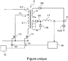
- the rectifier circuit has an output connected to a primary winding of an isolation transformer 6 in series with a switching switch T1.
- the primary winding 5 comprises an intermediate point which is connected to a switching switch T3 and which divides the primary winding 5 into a first part 5.1 and a second part 5.2.
- the switching switches T1 and T3 are power transistors such as a metal oxide oxide field effect transistor or metal oxide semiconductor field effect transistor (MOSFET) or an insulated gate bipolar transistor. IGBT (English “insulated gate bipolar transistor”).
- the switching switches T1 and T3 are connected to a control circuit or, more precisely, a switching control circuit 10 which will be described below.
- the isolation transformer 6 has a first secondary winding 7 which is of identical direction to the primary winding 5 and which is connected in series to an output line 8 of the converter via a diode D3 and a filtering coil (commonly called inductance ) L1.
- a freewheeling diode D6 connects the ground to the filtering coil L1 in a manner known per se to ensure the continuity of the current when the diode D3 does not conduct (restitution of the energy of the filtering coil L1).
- the isolation transformer 6 has a second secondary winding 9 which has a direction opposite to the primary winding 5 and which is connected via a diode D2 directly to the output line 8, that is to say downstream of the L1 coil.
- the switching control circuit 10 is a pulse width modulation control circuit arranged to control the switching switches T1 and T3 according to a comparison of an image voltage of a current consumed at the input of the converter with a signal in the form of a sinusoidal rectified double wave having an amplitude dependent on an error voltage between an output voltage of the converter and a reference voltage.
- the cutting control circuit 10 is identical to that of the document FR-A-2925790 .
- the gate of the switching switches T1, T3 is connected to the switching control circuit 10 by switches 31, 33 driven according to a presence of current at the output of the secondary winding 7 so that only one of said switches T1, T3 can be connected to the switching control circuit 10.
- the measuring circuit 30 is connected to the switches 31, 33 to control them.
- the part 5.2 of the primary winding 5 has an optimized value of self so that the part 5.2 can have in the first phase a pure "flyback" operation with the secondary winding 9.
- the part 5.1 of the primary winding 5 a an optimized self value for operation of the transformer 6 in "Forward" can be preferred in the second phase.
- the number of turns of part 5.2 is determined so that part 5.2 has a relatively low magnetising self to allow operation in "Flyback”.
- the number of turns of part 5.1 is greater than the number of turns in part 5.2 so that the number of turns of parts 5.1, 5.2 allow to obtain a magnetising self suitable for operation in "Forward".
- the principle of the converter consists in controlling, in pulse width modulation, the switching switches T1 and T3 so as to force the consumed current to follow a waveform identical to that of the voltage, namely a full wave rectified sinusoid.
- the switching switch T3 which is controlled by the control circuit of the input voltage. 10.
- the energy stored in the magnetic core of the isolation transformer 6 excites the second secondary winding 9 and is transmitted to the output line 8 through the diode D2.
- the operation of the converter is then similar to that of a FLYBACK type converter, to ensure a power consumption, used by the output, during the low amplitude phases of the rectified sinusoidal voltage.
- the diode D3 When the output voltage has increased to a threshold equal to the product of the input voltage and the transformation ratio, the diode D3 conducts and the energy of the magnetic core is transferred to the output line by the first winding 7, the diode D3 and the filtering coil L1. This current is detected and the connection of the switching control circuit 10 to the switching switch T1 is controlled by the measuring circuit 30.
- the operation of the converter implements the entire primary winding 5 and is similar to a FORWARD type operation.
- the converter also then has a FLYBACK-type minority mode of operation which contributes to the complete discharge of the magnetic core of the isolation transformer.
- the energy storage capacitor is a supercapacitor of very high capacity, of the order of a few hundred farads.
- the capacity and the number of energy storage capacitors are determined according to the amount of energy which one wishes to have in case of interruption of the supply.
- the discharge switch T2 is of the same type as the switching switch T1.
- the energy storage capacitor is charged (when the converter has a FORWARD mode of operation) via the third secondary winding and the associated diode.
- the coils coupled filtering devices provide a limitation of load current peaks and approximate regulation of the charging voltage. A disappearance of the supply voltage is detected by the discharge control circuit which drives the pulse width modulated discharge switch.
- the coupled filter coil assembly and energy storage capacitor then operates as a voltage booster with a resultant value enslaved to the normal operation operating setpoint.
- the discharge control circuit is arranged to adjust the duty ratio of its control to the charge level of the energy storage capacitor.
- the energy reserve is optional.
Landscapes
- Engineering & Computer Science (AREA)
- Power Engineering (AREA)
- Dc-Dc Converters (AREA)
Claims (1)
- Wechselstrom-/Gleichstromwandler, umfassend eine Primärwicklung (5) eines Isolationstransformators (6), die mit einem ersten Trennschalter (T1) verbunden ist, der an einen Steuerkreis (10) zur Steuerung mittels Pulsbreitenmodulation angeschlossen ist, wobei der Isolationstransformator eine erste Sekundärwicklung (7) umfasst, die eine zur Primärwicklung identische Wicklungsrichtung hat und die über eine Diode (D3) und eine Glättungsdrossel (L1) mit einer Ausgangsleitung (8) des Wandlers verbunden ist, sowie eine zweite Sekundärwicklung (9), die eine zur Primärwicklung entgegengesetzte Wicklungsrichtung hat und die über eine Diode (D2) direkt mit der Ausgangsleitung verbunden ist, wobei die Ausgangsleitung mit einem Ausgangskondensator (Cout) verbunden ist, dadurch gekennzeichnet, dass die Primärwicklung einen Zwischenpunkt umfasst, der mit einem zweiten Trennschalter (T3) verbunden ist, der an den Steuerkreis angeschlossen ist, und der die Primärwicklung in einen ersten Teil (5.1) und einen zweiten Teil (5.2) unterteilt, wobei die Schalter so gesteuert werden, dass sie eine Verbindung nur des zweiten Teils oder beider Teile in Abhängigkeit eines Vorhandenseins eines Stroms am Ausgang der ersten Sekundärwicklung ermöglichen, wobei die Primärwicklung eine optimierte Gesamtwindungszahl hat, um mit der ersten Sekundärwicklung einen "Durchlass"-Betrieb zu haben.
Applications Claiming Priority (2)
| Application Number | Priority Date | Filing Date | Title |
|---|---|---|---|
| FR1052089A FR2958094B1 (fr) | 2010-03-23 | 2010-03-23 | Convertisseur alternatif / continu a isolement galvanique |
| PCT/EP2011/001431 WO2011116942A2 (fr) | 2010-03-23 | 2011-03-23 | Convertisseur alternatif/continu a isolement galvanique |
Publications (2)
| Publication Number | Publication Date |
|---|---|
| EP2550728A2 EP2550728A2 (de) | 2013-01-30 |
| EP2550728B1 true EP2550728B1 (de) | 2017-05-03 |
Family
ID=43034543
Family Applications (1)
| Application Number | Title | Priority Date | Filing Date |
|---|---|---|---|
| EP11710710.2A Active EP2550728B1 (de) | 2010-03-23 | 2011-03-23 | Gleichrichter mit galvanischer Isolierung |
Country Status (3)
| Country | Link |
|---|---|
| EP (1) | EP2550728B1 (de) |
| FR (1) | FR2958094B1 (de) |
| WO (1) | WO2011116942A2 (de) |
Families Citing this family (2)
| Publication number | Priority date | Publication date | Assignee | Title |
|---|---|---|---|---|
| EP3316464B1 (de) * | 2016-10-26 | 2020-04-08 | ABB Schweiz AG | Schaltnetzteil mit leistungsfaktorkorrektur |
| CN108933539B (zh) * | 2017-05-24 | 2020-01-14 | 明纬(广州)电子有限公司 | 同步整流装置 |
Family Cites Families (3)
| Publication number | Priority date | Publication date | Assignee | Title |
|---|---|---|---|---|
| JPS5290201A (en) * | 1976-01-23 | 1977-07-29 | Sony Corp | Input circuit |
| FR2925790B1 (fr) * | 2007-12-19 | 2010-01-15 | Sagem Defense Securite | Convertisseur alternatif/continu a isolement galvanique |
| US8106636B2 (en) * | 2008-02-22 | 2012-01-31 | Murata Power Solutions | Method and apparatus for power conversion with wide input voltage range |
-
2010
- 2010-03-23 FR FR1052089A patent/FR2958094B1/fr active Active
-
2011
- 2011-03-23 WO PCT/EP2011/001431 patent/WO2011116942A2/fr not_active Ceased
- 2011-03-23 EP EP11710710.2A patent/EP2550728B1/de active Active
Also Published As
| Publication number | Publication date |
|---|---|
| FR2958094B1 (fr) | 2012-03-30 |
| WO2011116942A2 (fr) | 2011-09-29 |
| WO2011116942A3 (fr) | 2011-11-24 |
| EP2550728A2 (de) | 2013-01-30 |
| FR2958094A1 (fr) | 2011-09-30 |
Similar Documents
| Publication | Publication Date | Title |
|---|---|---|
| EP2232687B1 (de) | Wechselstrom/gleichstromwandler mit galvanischer trennung | |
| EP3403872B1 (de) | Ladesystem für ein elektro- oder hybridfahrzeug | |
| EP2742585B1 (de) | Ac/dc-wandler mit galvanischer isolierung und signalkorrektor | |
| WO2007122268A2 (fr) | Dispositif de transfert de puissance isole perfectionne | |
| FR3004870A1 (fr) | Procede et dispositif de commande d'un convertisseur multiphase courant continu-courant continu a resonance, et convertisseur multiphase correspondant | |
| EP3161951B1 (de) | Spannungswandler mit einer isolierten gleichstromwandlerschaltung | |
| FR3037453A1 (fr) | Convertisseur continu-continu pour le pilotage d'un onduleur de ventilateur d'aeronef, procede de commande et ventilateur associes | |
| EP3729627B1 (de) | Gleichspannungswandler für ein bidirektionales ladegerät | |
| WO2010029222A1 (fr) | Dispositif convertisseur et alimentation sans interruption équipée d'un tel dispositif | |
| FR3104846A1 (fr) | Système électrique pour la conversion de tension continue et la charge de batteries d’alimentation | |
| WO2011116942A2 (fr) | Convertisseur alternatif/continu a isolement galvanique | |
| EP3161950B1 (de) | Spannungswandler mit einer isolierten gleichstromwandlerschaltung | |
| FR2478392A1 (fr) | Chargeur de batterie | |
| EP3163732B1 (de) | Bidirektionelles leistungswandlungssystem für einphasige elektrische ladung, und entsprechendes leistungswandlungsverfahren | |
| EP3685485B1 (de) | Verfahren zur steuerung eines ladesystems einer traktionbatterie | |
| FR3008258A1 (fr) | Convertisseur ac/dc a isolement galvanique et correcteur de signal | |
| WO2010004190A1 (fr) | Poste de soudage a l'arc a onduleur a commutation douce quasi resonant optimise | |
| EP0379696B1 (de) | Spannungserhöhungskonverter mit Entmagnetisierungs-Energierückgewinnungswicklung | |
| FR3078212A1 (fr) | Convertisseur dc-dc pour chargeur bidirectionnel. | |
| EP0924844B1 (de) | Aus einer Reihenschaltung von quasiresonanten Zellen aufgebauter Hochspannungsschalter | |
| FR2986678A1 (fr) | Convertisseur de tension pour chargeur de batterie |
Legal Events
| Date | Code | Title | Description |
|---|---|---|---|
| PUAI | Public reference made under article 153(3) epc to a published international application that has entered the european phase |
Free format text: ORIGINAL CODE: 0009012 |
|
| 17P | Request for examination filed |
Effective date: 20120913 |
|
| AK | Designated contracting states |
Kind code of ref document: A2 Designated state(s): AL AT BE BG CH CY CZ DE DK EE ES FI FR GB GR HR HU IE IS IT LI LT LU LV MC MK MT NL NO PL PT RO RS SE SI SK SM TR |
|
| DAX | Request for extension of the european patent (deleted) | ||
| RAP1 | Party data changed (applicant data changed or rights of an application transferred) |
Owner name: SAGEM DEFENSE SECURITE |
|
| RAP1 | Party data changed (applicant data changed or rights of an application transferred) |
Owner name: SAFRAN ELECTRONICS & DEFENSE |
|
| GRAP | Despatch of communication of intention to grant a patent |
Free format text: ORIGINAL CODE: EPIDOSNIGR1 |
|
| STAA | Information on the status of an ep patent application or granted ep patent |
Free format text: STATUS: GRANT OF PATENT IS INTENDED |
|
| INTG | Intention to grant announced |
Effective date: 20161110 |
|
| GRAS | Grant fee paid |
Free format text: ORIGINAL CODE: EPIDOSNIGR3 |
|
| GRAA | (expected) grant |
Free format text: ORIGINAL CODE: 0009210 |
|
| STAA | Information on the status of an ep patent application or granted ep patent |
Free format text: STATUS: THE PATENT HAS BEEN GRANTED |
|
| RIN1 | Information on inventor provided before grant (corrected) |
Inventor name: FOURMONT, TONY |
|
| AK | Designated contracting states |
Kind code of ref document: B1 Designated state(s): AL AT BE BG CH CY CZ DE DK EE ES FI FR GB GR HR HU IE IS IT LI LT LU LV MC MK MT NL NO PL PT RO RS SE SI SK SM TR |
|
| REG | Reference to a national code |
Ref country code: GB Ref legal event code: FG4D Free format text: NOT ENGLISH |
|
| REG | Reference to a national code |
Ref country code: AT Ref legal event code: REF Ref document number: 891013 Country of ref document: AT Kind code of ref document: T Effective date: 20170515 Ref country code: CH Ref legal event code: EP |
|
| REG | Reference to a national code |
Ref country code: IE Ref legal event code: FG4D Free format text: LANGUAGE OF EP DOCUMENT: FRENCH |
|
| REG | Reference to a national code |
Ref country code: DE Ref legal event code: R096 Ref document number: 602011037543 Country of ref document: DE |
|
| REG | Reference to a national code |
Ref country code: NL Ref legal event code: MP Effective date: 20170503 |
|
| REG | Reference to a national code |
Ref country code: AT Ref legal event code: MK05 Ref document number: 891013 Country of ref document: AT Kind code of ref document: T Effective date: 20170503 |
|
| REG | Reference to a national code |
Ref country code: LT Ref legal event code: MG4D |
|
| PG25 | Lapsed in a contracting state [announced via postgrant information from national office to epo] |
Ref country code: ES Free format text: LAPSE BECAUSE OF FAILURE TO SUBMIT A TRANSLATION OF THE DESCRIPTION OR TO PAY THE FEE WITHIN THE PRESCRIBED TIME-LIMIT Effective date: 20170503 Ref country code: NO Free format text: LAPSE BECAUSE OF FAILURE TO SUBMIT A TRANSLATION OF THE DESCRIPTION OR TO PAY THE FEE WITHIN THE PRESCRIBED TIME-LIMIT Effective date: 20170803 Ref country code: HR Free format text: LAPSE BECAUSE OF FAILURE TO SUBMIT A TRANSLATION OF THE DESCRIPTION OR TO PAY THE FEE WITHIN THE PRESCRIBED TIME-LIMIT Effective date: 20170503 Ref country code: FI Free format text: LAPSE BECAUSE OF FAILURE TO SUBMIT A TRANSLATION OF THE DESCRIPTION OR TO PAY THE FEE WITHIN THE PRESCRIBED TIME-LIMIT Effective date: 20170503 Ref country code: LT Free format text: LAPSE BECAUSE OF FAILURE TO SUBMIT A TRANSLATION OF THE DESCRIPTION OR TO PAY THE FEE WITHIN THE PRESCRIBED TIME-LIMIT Effective date: 20170503 Ref country code: GR Free format text: LAPSE BECAUSE OF FAILURE TO SUBMIT A TRANSLATION OF THE DESCRIPTION OR TO PAY THE FEE WITHIN THE PRESCRIBED TIME-LIMIT Effective date: 20170804 Ref country code: AT Free format text: LAPSE BECAUSE OF FAILURE TO SUBMIT A TRANSLATION OF THE DESCRIPTION OR TO PAY THE FEE WITHIN THE PRESCRIBED TIME-LIMIT Effective date: 20170503 |
|
| PG25 | Lapsed in a contracting state [announced via postgrant information from national office to epo] |
Ref country code: BG Free format text: LAPSE BECAUSE OF FAILURE TO SUBMIT A TRANSLATION OF THE DESCRIPTION OR TO PAY THE FEE WITHIN THE PRESCRIBED TIME-LIMIT Effective date: 20170803 Ref country code: SE Free format text: LAPSE BECAUSE OF FAILURE TO SUBMIT A TRANSLATION OF THE DESCRIPTION OR TO PAY THE FEE WITHIN THE PRESCRIBED TIME-LIMIT Effective date: 20170503 Ref country code: PL Free format text: LAPSE BECAUSE OF FAILURE TO SUBMIT A TRANSLATION OF THE DESCRIPTION OR TO PAY THE FEE WITHIN THE PRESCRIBED TIME-LIMIT Effective date: 20170503 Ref country code: LV Free format text: LAPSE BECAUSE OF FAILURE TO SUBMIT A TRANSLATION OF THE DESCRIPTION OR TO PAY THE FEE WITHIN THE PRESCRIBED TIME-LIMIT Effective date: 20170503 Ref country code: NL Free format text: LAPSE BECAUSE OF FAILURE TO SUBMIT A TRANSLATION OF THE DESCRIPTION OR TO PAY THE FEE WITHIN THE PRESCRIBED TIME-LIMIT Effective date: 20170503 Ref country code: IS Free format text: LAPSE BECAUSE OF FAILURE TO SUBMIT A TRANSLATION OF THE DESCRIPTION OR TO PAY THE FEE WITHIN THE PRESCRIBED TIME-LIMIT Effective date: 20170903 Ref country code: RS Free format text: LAPSE BECAUSE OF FAILURE TO SUBMIT A TRANSLATION OF THE DESCRIPTION OR TO PAY THE FEE WITHIN THE PRESCRIBED TIME-LIMIT Effective date: 20170503 |
|
| PG25 | Lapsed in a contracting state [announced via postgrant information from national office to epo] |
Ref country code: CZ Free format text: LAPSE BECAUSE OF FAILURE TO SUBMIT A TRANSLATION OF THE DESCRIPTION OR TO PAY THE FEE WITHIN THE PRESCRIBED TIME-LIMIT Effective date: 20170503 Ref country code: SK Free format text: LAPSE BECAUSE OF FAILURE TO SUBMIT A TRANSLATION OF THE DESCRIPTION OR TO PAY THE FEE WITHIN THE PRESCRIBED TIME-LIMIT Effective date: 20170503 Ref country code: RO Free format text: LAPSE BECAUSE OF FAILURE TO SUBMIT A TRANSLATION OF THE DESCRIPTION OR TO PAY THE FEE WITHIN THE PRESCRIBED TIME-LIMIT Effective date: 20170503 Ref country code: EE Free format text: LAPSE BECAUSE OF FAILURE TO SUBMIT A TRANSLATION OF THE DESCRIPTION OR TO PAY THE FEE WITHIN THE PRESCRIBED TIME-LIMIT Effective date: 20170503 Ref country code: DK Free format text: LAPSE BECAUSE OF FAILURE TO SUBMIT A TRANSLATION OF THE DESCRIPTION OR TO PAY THE FEE WITHIN THE PRESCRIBED TIME-LIMIT Effective date: 20170503 |
|
| REG | Reference to a national code |
Ref country code: DE Ref legal event code: R097 Ref document number: 602011037543 Country of ref document: DE |
|
| REG | Reference to a national code |
Ref country code: FR Ref legal event code: PLFP Year of fee payment: 8 |
|
| PG25 | Lapsed in a contracting state [announced via postgrant information from national office to epo] |
Ref country code: SM Free format text: LAPSE BECAUSE OF FAILURE TO SUBMIT A TRANSLATION OF THE DESCRIPTION OR TO PAY THE FEE WITHIN THE PRESCRIBED TIME-LIMIT Effective date: 20170503 Ref country code: IT Free format text: LAPSE BECAUSE OF FAILURE TO SUBMIT A TRANSLATION OF THE DESCRIPTION OR TO PAY THE FEE WITHIN THE PRESCRIBED TIME-LIMIT Effective date: 20170503 |
|
| PLBE | No opposition filed within time limit |
Free format text: ORIGINAL CODE: 0009261 |
|
| STAA | Information on the status of an ep patent application or granted ep patent |
Free format text: STATUS: NO OPPOSITION FILED WITHIN TIME LIMIT |
|
| 26N | No opposition filed |
Effective date: 20180206 |
|
| PG25 | Lapsed in a contracting state [announced via postgrant information from national office to epo] |
Ref country code: SI Free format text: LAPSE BECAUSE OF FAILURE TO SUBMIT A TRANSLATION OF THE DESCRIPTION OR TO PAY THE FEE WITHIN THE PRESCRIBED TIME-LIMIT Effective date: 20170503 |
|
| PG25 | Lapsed in a contracting state [announced via postgrant information from national office to epo] |
Ref country code: MT Free format text: LAPSE BECAUSE OF FAILURE TO SUBMIT A TRANSLATION OF THE DESCRIPTION OR TO PAY THE FEE WITHIN THE PRESCRIBED TIME-LIMIT Effective date: 20170503 |
|
| REG | Reference to a national code |
Ref country code: CH Ref legal event code: PL |
|
| PG25 | Lapsed in a contracting state [announced via postgrant information from national office to epo] |
Ref country code: MC Free format text: LAPSE BECAUSE OF FAILURE TO SUBMIT A TRANSLATION OF THE DESCRIPTION OR TO PAY THE FEE WITHIN THE PRESCRIBED TIME-LIMIT Effective date: 20170503 |
|
| REG | Reference to a national code |
Ref country code: BE Ref legal event code: MM Effective date: 20180331 |
|
| REG | Reference to a national code |
Ref country code: IE Ref legal event code: MM4A |
|
| PG25 | Lapsed in a contracting state [announced via postgrant information from national office to epo] |
Ref country code: LU Free format text: LAPSE BECAUSE OF NON-PAYMENT OF DUE FEES Effective date: 20180323 |
|
| PG25 | Lapsed in a contracting state [announced via postgrant information from national office to epo] |
Ref country code: IE Free format text: LAPSE BECAUSE OF NON-PAYMENT OF DUE FEES Effective date: 20180323 |
|
| PG25 | Lapsed in a contracting state [announced via postgrant information from national office to epo] |
Ref country code: BE Free format text: LAPSE BECAUSE OF NON-PAYMENT OF DUE FEES Effective date: 20180331 Ref country code: LI Free format text: LAPSE BECAUSE OF NON-PAYMENT OF DUE FEES Effective date: 20180331 Ref country code: CH Free format text: LAPSE BECAUSE OF NON-PAYMENT OF DUE FEES Effective date: 20180331 |
|
| PG25 | Lapsed in a contracting state [announced via postgrant information from national office to epo] |
Ref country code: TR Free format text: LAPSE BECAUSE OF FAILURE TO SUBMIT A TRANSLATION OF THE DESCRIPTION OR TO PAY THE FEE WITHIN THE PRESCRIBED TIME-LIMIT Effective date: 20170503 |
|
| PG25 | Lapsed in a contracting state [announced via postgrant information from national office to epo] |
Ref country code: PT Free format text: LAPSE BECAUSE OF FAILURE TO SUBMIT A TRANSLATION OF THE DESCRIPTION OR TO PAY THE FEE WITHIN THE PRESCRIBED TIME-LIMIT Effective date: 20170503 Ref country code: HU Free format text: LAPSE BECAUSE OF FAILURE TO SUBMIT A TRANSLATION OF THE DESCRIPTION OR TO PAY THE FEE WITHIN THE PRESCRIBED TIME-LIMIT; INVALID AB INITIO Effective date: 20110323 |
|
| PG25 | Lapsed in a contracting state [announced via postgrant information from national office to epo] |
Ref country code: MK Free format text: LAPSE BECAUSE OF NON-PAYMENT OF DUE FEES Effective date: 20170503 Ref country code: CY Free format text: LAPSE BECAUSE OF FAILURE TO SUBMIT A TRANSLATION OF THE DESCRIPTION OR TO PAY THE FEE WITHIN THE PRESCRIBED TIME-LIMIT Effective date: 20170503 |
|
| PG25 | Lapsed in a contracting state [announced via postgrant information from national office to epo] |
Ref country code: AL Free format text: LAPSE BECAUSE OF FAILURE TO SUBMIT A TRANSLATION OF THE DESCRIPTION OR TO PAY THE FEE WITHIN THE PRESCRIBED TIME-LIMIT Effective date: 20170503 |
|
| PGFP | Annual fee paid to national office [announced via postgrant information from national office to epo] |
Ref country code: GB Payment date: 20260324 Year of fee payment: 16 |
|
| PGFP | Annual fee paid to national office [announced via postgrant information from national office to epo] |
Ref country code: DE Payment date: 20260320 Year of fee payment: 16 |
|
| PGFP | Annual fee paid to national office [announced via postgrant information from national office to epo] |
Ref country code: FR Payment date: 20260324 Year of fee payment: 16 |