EP2551018A2 - Centrage d'une électrode sous haute tension par force magnétique - Google Patents
Centrage d'une électrode sous haute tension par force magnétique Download PDFInfo
- Publication number
- EP2551018A2 EP2551018A2 EP12178046A EP12178046A EP2551018A2 EP 2551018 A2 EP2551018 A2 EP 2551018A2 EP 12178046 A EP12178046 A EP 12178046A EP 12178046 A EP12178046 A EP 12178046A EP 2551018 A2 EP2551018 A2 EP 2551018A2
- Authority
- EP
- European Patent Office
- Prior art keywords
- magnetic element
- magnets
- electrode
- magnetic
- magnet
- Prior art date
- Legal status (The legal status is an assumption and is not a legal conclusion. Google has not performed a legal analysis and makes no representation as to the accuracy of the status listed.)
- Granted
Links
- 230000005291 magnetic effect Effects 0.000 title claims abstract description 178
- 238000000034 method Methods 0.000 claims abstract description 10
- 239000007921 spray Substances 0.000 claims description 80
- 239000012212 insulator Substances 0.000 claims description 10
- 230000002940 repellent Effects 0.000 claims description 5
- 239000005871 repellent Substances 0.000 claims description 5
- XEEYBQQBJWHFJM-UHFFFAOYSA-N Iron Chemical compound [Fe] XEEYBQQBJWHFJM-UHFFFAOYSA-N 0.000 claims description 4
- 238000009420 retrofitting Methods 0.000 claims description 3
- 229910052742 iron Inorganic materials 0.000 claims description 2
- 238000005507 spraying Methods 0.000 claims 1
- 230000002093 peripheral effect Effects 0.000 description 20
- 230000006641 stabilisation Effects 0.000 description 10
- 238000011105 stabilization Methods 0.000 description 10
- 239000000725 suspension Substances 0.000 description 8
- 230000000694 effects Effects 0.000 description 7
- 238000001556 precipitation Methods 0.000 description 5
- 230000001681 protective effect Effects 0.000 description 5
- 230000001846 repelling effect Effects 0.000 description 5
- 238000004140 cleaning Methods 0.000 description 4
- 241001295925 Gegenes Species 0.000 description 2
- 230000001687 destabilization Effects 0.000 description 2
- 238000006073 displacement reaction Methods 0.000 description 2
- 239000000428 dust Substances 0.000 description 2
- 239000012717 electrostatic precipitator Substances 0.000 description 2
- 238000009434 installation Methods 0.000 description 2
- 229910001172 neodymium magnet Inorganic materials 0.000 description 2
- 239000002245 particle Substances 0.000 description 2
- 238000004544 sputter deposition Methods 0.000 description 2
- 239000002699 waste material Substances 0.000 description 2
- 229910000669 Chrome steel Inorganic materials 0.000 description 1
- 239000004809 Teflon Substances 0.000 description 1
- 229920006362 Teflon® Polymers 0.000 description 1
- 238000009825 accumulation Methods 0.000 description 1
- 230000002411 adverse Effects 0.000 description 1
- 229910000828 alnico Inorganic materials 0.000 description 1
- 230000001174 ascending effect Effects 0.000 description 1
- 238000005452 bending Methods 0.000 description 1
- 230000001680 brushing effect Effects 0.000 description 1
- 238000013016 damping Methods 0.000 description 1
- 230000003247 decreasing effect Effects 0.000 description 1
- 230000007547 defect Effects 0.000 description 1
- 230000001419 dependent effect Effects 0.000 description 1
- 238000011161 development Methods 0.000 description 1
- 230000018109 developmental process Effects 0.000 description 1
- 230000005684 electric field Effects 0.000 description 1
- 238000010292 electrical insulation Methods 0.000 description 1
- 238000005516 engineering process Methods 0.000 description 1
- 230000005294 ferromagnetic effect Effects 0.000 description 1
- 238000001914 filtration Methods 0.000 description 1
- 230000005484 gravity Effects 0.000 description 1
- 238000009413 insulation Methods 0.000 description 1
- 238000012423 maintenance Methods 0.000 description 1
- 239000000463 material Substances 0.000 description 1
- 229910052751 metal Inorganic materials 0.000 description 1
- 239000002184 metal Substances 0.000 description 1
- 239000003595 mist Substances 0.000 description 1
- 230000036961 partial effect Effects 0.000 description 1
- 239000004033 plastic Substances 0.000 description 1
- 238000000746 purification Methods 0.000 description 1
- 230000002829 reductive effect Effects 0.000 description 1
- 238000010079 rubber tapping Methods 0.000 description 1
- 230000001629 suppression Effects 0.000 description 1
- 238000003466 welding Methods 0.000 description 1
Images





Classifications
-
- B—PERFORMING OPERATIONS; TRANSPORTING
- B03—SEPARATION OF SOLID MATERIALS USING LIQUIDS OR USING PNEUMATIC TABLES OR JIGS; MAGNETIC OR ELECTROSTATIC SEPARATION OF SOLID MATERIALS FROM SOLID MATERIALS OR FLUIDS; SEPARATION BY HIGH-VOLTAGE ELECTRIC FIELDS
- B03C—MAGNETIC OR ELECTROSTATIC SEPARATION OF SOLID MATERIALS FROM SOLID MATERIALS OR FLUIDS; SEPARATION BY HIGH-VOLTAGE ELECTRIC FIELDS
- B03C3/00—Separating dispersed particles from gases or vapour, e.g. air, by electrostatic effect
- B03C3/34—Constructional details or accessories or operation thereof
- B03C3/40—Electrode constructions
- B03C3/41—Ionising-electrodes
-
- B—PERFORMING OPERATIONS; TRANSPORTING
- B03—SEPARATION OF SOLID MATERIALS USING LIQUIDS OR USING PNEUMATIC TABLES OR JIGS; MAGNETIC OR ELECTROSTATIC SEPARATION OF SOLID MATERIALS FROM SOLID MATERIALS OR FLUIDS; SEPARATION BY HIGH-VOLTAGE ELECTRIC FIELDS
- B03C—MAGNETIC OR ELECTROSTATIC SEPARATION OF SOLID MATERIALS FROM SOLID MATERIALS OR FLUIDS; SEPARATION BY HIGH-VOLTAGE ELECTRIC FIELDS
- B03C3/00—Separating dispersed particles from gases or vapour, e.g. air, by electrostatic effect
- B03C3/34—Constructional details or accessories or operation thereof
- B03C3/40—Electrode constructions
- B03C3/45—Collecting-electrodes
- B03C3/49—Collecting-electrodes tubular
-
- B—PERFORMING OPERATIONS; TRANSPORTING
- B03—SEPARATION OF SOLID MATERIALS USING LIQUIDS OR USING PNEUMATIC TABLES OR JIGS; MAGNETIC OR ELECTROSTATIC SEPARATION OF SOLID MATERIALS FROM SOLID MATERIALS OR FLUIDS; SEPARATION BY HIGH-VOLTAGE ELECTRIC FIELDS
- B03C—MAGNETIC OR ELECTROSTATIC SEPARATION OF SOLID MATERIALS FROM SOLID MATERIALS OR FLUIDS; SEPARATION BY HIGH-VOLTAGE ELECTRIC FIELDS
- B03C3/00—Separating dispersed particles from gases or vapour, e.g. air, by electrostatic effect
- B03C3/34—Constructional details or accessories or operation thereof
- B03C3/66—Applications of electricity supply techniques
- B03C3/70—Applications of electricity supply techniques insulating in electric separators
-
- B—PERFORMING OPERATIONS; TRANSPORTING
- B03—SEPARATION OF SOLID MATERIALS USING LIQUIDS OR USING PNEUMATIC TABLES OR JIGS; MAGNETIC OR ELECTROSTATIC SEPARATION OF SOLID MATERIALS FROM SOLID MATERIALS OR FLUIDS; SEPARATION BY HIGH-VOLTAGE ELECTRIC FIELDS
- B03C—MAGNETIC OR ELECTROSTATIC SEPARATION OF SOLID MATERIALS FROM SOLID MATERIALS OR FLUIDS; SEPARATION BY HIGH-VOLTAGE ELECTRIC FIELDS
- B03C3/00—Separating dispersed particles from gases or vapour, e.g. air, by electrostatic effect
- B03C3/34—Constructional details or accessories or operation thereof
- B03C3/86—Electrode-carrying means
-
- B—PERFORMING OPERATIONS; TRANSPORTING
- B03—SEPARATION OF SOLID MATERIALS USING LIQUIDS OR USING PNEUMATIC TABLES OR JIGS; MAGNETIC OR ELECTROSTATIC SEPARATION OF SOLID MATERIALS FROM SOLID MATERIALS OR FLUIDS; SEPARATION BY HIGH-VOLTAGE ELECTRIC FIELDS
- B03C—MAGNETIC OR ELECTROSTATIC SEPARATION OF SOLID MATERIALS FROM SOLID MATERIALS OR FLUIDS; SEPARATION BY HIGH-VOLTAGE ELECTRIC FIELDS
- B03C2201/00—Details of magnetic or electrostatic separation
- B03C2201/04—Ionising electrode being a wire
-
- B—PERFORMING OPERATIONS; TRANSPORTING
- B03—SEPARATION OF SOLID MATERIALS USING LIQUIDS OR USING PNEUMATIC TABLES OR JIGS; MAGNETIC OR ELECTROSTATIC SEPARATION OF SOLID MATERIALS FROM SOLID MATERIALS OR FLUIDS; SEPARATION BY HIGH-VOLTAGE ELECTRIC FIELDS
- B03C—MAGNETIC OR ELECTROSTATIC SEPARATION OF SOLID MATERIALS FROM SOLID MATERIALS OR FLUIDS; SEPARATION BY HIGH-VOLTAGE ELECTRIC FIELDS
- B03C2201/00—Details of magnetic or electrostatic separation
- B03C2201/08—Ionising electrode being a rod
Definitions
- the present invention relates to an electrostatic filter system according to the preamble of the independent claim and a filter set according to the preamble of a further independent claim. Furthermore, the present invention relates to a method for operating an electrostatic filter system and a method for assembling the inventive filter set to an exhaust pipe or an exhaust stack and the use of the filter set for equipping or retrofitting exhaust systems.
- Electrostatic separators for exhaust gas purification generally include at least one spray electrode and a precipitation electrode as the counter electrode.
- the surfaces of the electrodes face each other as far as possible distance uniform.
- the surface of the collecting electrode can be made quite large in comparison to the surface of the spray.
- Known electrostatic precipitators consist for example of parallel collecting electrodes, which are grounded together with the housing.
- the collecting electrodes form passages through which the gas to be purified flows.
- spray electrodes Between the precipitation electrodes in the lanes are spray electrodes. These are suspended electrically isolated and are supplied with rectified high voltage, which is usually between 20 to 100kV.
- the dust particles or mist droplets contained in the exhaust gas are electrically negatively charged during flow through the separator between the electrodes and transported under the influence of a strong electric field to the grounded collecting electrodes where they are separated or filtered out.
- the spray electrodes are usually mounted on a fixed frame. By this measure, the position of the electrodes is fixed.
- the electrodes are often hung on one side and provided with a draw weight.
- the electrodes are often connected together via a frame and thus held in position.
- the high-voltage electrode is at a potential up to about 100kV, the precipitation surface at the potential of the earth. Due to the different potentials, the opposing poles attract each other and, when approaching each other, can lead to a short circuit which impairs the operation.
- the electrode is normally tensioned between two points or provided with a reset weight.
- the restoring moment M gr caused by the weight F g remains approximately constant at a constant deflection S1 (eg 0.1 m) and changing electrode length L e .
- the restoring force F gr becomes smaller with a longer electrode (smaller deflection angle ⁇ )
- the lever electrowetting force
- a system with tube filter is disclosed.
- the suspended electrodes can be vibrated by electromagnets and thereby cleaned.
- the magnets can also serve to stabilize the electrodes. This is accomplished in one embodiment by pairs of magnets, wherein the respective first magnet of a pair is attached to the electrodes as weighting weight and the respective second magnet of a pair is arranged at a distance below the respective first, weighting magnet in the exhaust duct.
- the mutual vertical attraction of the magnets of each pair of magnets ensures a vertical tightening of the electrode.
- a disadvantage of this embodiment is that the lower magnets are mounted on a scaffold, which is arranged in the exhaust pipe. As a result, the effective pipe diameter is reduced, the passage for cleaning brushes is blocked and defects and maintenance work on scaffold and / or magnet are due to the poor accessibility only partially correctable.
- All hanging electrodes are attached at their lower end to a common weighting arrangement.
- the respective first magnets of four pairs of magnets are mounted evenly distributed on the edge of the weighting arrangement.
- the second magnets (counter magnets) of each pair are fixed at a distance from the respective first magnets of a pair on the inner periphery of the exhaust passage.
- This arrangement should allow a centering of the magnets.
- the clamping of the discharge electrodes in the axial direction is shown by the outer magnets, which are axially offset below the magnets attached to the discharge electrodes, act attractively on the magnets of the discharge electrodes.
- the centering and stabilization of elongated electrodes in the exhaust duct should be improved.
- a method of centering and stabilization is to be found, which is suitable for short and long high voltage electrodes, which may be flexible or rigid.
- the method should also be effective for very narrow and / or curved exhaust pipes.
- the cleaning should be possible in the simplest way with the brush from above or below.
- a free-hanging high voltage electrode is particularly well centered in the said electrostatic filter system and stabilized due to the magnetic repulsion forces.
- the magnetic centering disclosed here thus also serves for vibration damping and possibly vibration suppression.
- the elongate spray electrode can be designed as a rod electrode.
- a rod is expediently stiff, whereby vibrations during operation are suppressed.
- the rod is also bendable or flexible at the same time. The bending ability may e.g. be advantageous when inserting the rod electrode in the exhaust passage. When cleaning with a brush also differs a flexible rod better. All these advantages are e.g. united in a along the longitudinal direction cambered rod.
- another electrode may be used, e.g. a cable electrode, a wire electrode or a chain electrode.
- the Magnetzentriansssystem shown for electrostatic filter systems is equipped with only a single spray.
- the illustrated magnet centering system is particularly advantageous if the spray electrode is particularly long (for example at least 3 meters, optionally at least 4 meters or even 5 meters or longer).
- the magnetic field lines in the mutual area of influence of the magnetic elements essentially run in such a way (for example rectified parallel), so that a mutual repulsion of the magnets results.
- the first magnetic element is expediently designed as a bar magnet.
- the north-south axis is in this case advantageously aligned parallel to the longitudinal direction of the elongated or elongate spray electrode.
- the first central magnetic element e.g. Permanent magnets, AlNiCo magnets, neodymium magnets.
- the type of usable magnets is conveniently determined based on the given temperature conditions during operation.
- the second magnetic element includes one or more individual magnets, which may comprise a magnet, e.g. is shaped as a ring or which individual magnets e.g. are arranged ring-like or coronary.
- the individual magnets of the second magnetic element are advantageously spaced from each other.
- the second magnetic element surrounds - or surrounds, surrounds or surrounds - the first magnetic element preferably by, the second magnetic element (ie in particular the individual magnets of the second magnetic element or a ring magnet) and the first Magnetic element approximately on a plane (in particular on a horizontal plane or approximately at the same height) are arranged. Due to this arrangement, the magnetic elements can act on each other in such a way that the first magnetic element is influenced by the opposing magnetic forces. In particular, the second magnetic element or its individual magnets can surround the first magnetic element in a satellite-like manner.
- the small height difference between the possible positions of the first magnetic element may be considered as an approximately equal height level region. This height difference is usually within an acceptable tolerance for the first and second magnetic element to be placed together.
- the second magnetic element or the individual magnets of the second magnetic element is or are advantageously arranged approximately on the same plane, in particular approximately the same height as the first magnetic element.
- the term "about” in this context means that there is some tolerance for deviations. The tolerance range may depend on the magnets used and their mutual arrangement. For magnets, which are arranged with their north-south axis perpendicular to the common plane, it can be approximately assumed that a mutual displacement of the common plane by half its length (ie by half the length of the north-south axis) is tolerable , If the length of the north-south axis of the first and second magnets or of the first and second magnetic element is not the same, then the length of the shorter north-south axis is relevant.
- the type of magnet and the dimensions of the magnet are chosen such that said tolerance is in a range of at least ⁇ 5 cm, more preferably at least ⁇ 10 cm, more preferably at least ⁇ 5 cm. If the magnets have unequal dimensions, the respective center of gravity can be used as a reference for its height. The centering due repulsive magnetic forces may therefore possibly still work even with an existing height difference between the first and second magnetic element, provided that the magnetic forces are designed accordingly strong.
- the second magnetic element comprises a plurality of individual magnets, in particular at least three magnets, preferably 12 to 20 magnets, which preferably strung apart a row (magnetic ring) form around the exhaust passage.
- the second magnetic element may be e.g. include at least one magnetic ring, which magnetic ring the exhaust duct is placed around this comprehensive.
- the second magnetic element may comprise two or more magnet pieces which, in combination and due to their shape (e.g., part-circular), substantially annularly surround the exhaust space. If the second magnetic element consists of a plurality of magnets (or if the second magnetic element is an arrangement of a plurality of magnets), then these magnets are preferably aligned in such a way that they repel each other.
- the second magnetic element may e.g. Several bar magnets, several horseshoe magnets or more magnets with iron yoke include. It would also be possible to combine different types of magnets and / or magnetic forms. For ease of assembly, all magnets, which in combination make up the second magnetic element, have approximately the same strength or force field. Magnets of equal strength can e.g. be arranged on a circular line uniformly spaced from each other along the inner or outer periphery of an exhaust pipe or chimney and fixed thereto.
- the second peripheral magnetic element e.g. Permanent magnets, AlNi-Co magnets, Neodymium magnets.
- heat-resistant magnets are also interesting here, since an exhaust gas flow compared to the ambient temperature usually has a significantly elevated temperature and would otherwise demagnetize the magnets.
- the individual magnets of the second magnetic element expediently clamp an imaginary connecting line which surrounds the first magnetic element or at least its axial extension. Due to the mutual repulsive influence of the field lines, the first, central magnetic element and thus the spray electrode can be caught or held in position.
- the individual magnets of the second magnetic element preferably clamp an imaginary connecting line which surrounds the exhaust gas channel.
- these imaginary lines do not intersect the interior of the exhaust passage but extend further outwards, i.e., outward. at least tangentially to the inner wall of the exhaust passage or spaced radially further out.
- the imaginary connecting line thus advantageously surrounds the horizontal cross section of an exhaust gas duct or of an interior of a chimney.
- the second magnetic element is fixed to the outer wall of the exhaust passage. This has the advantage that the magnetic element does not have to be polluted and cumbersome to clean in the exhaust duct. In addition, the exhaust duct remains free and the gas can escape escaping hinderungsok. Alternatively, the second magnetic element could be fixed to the inner wall of the exhaust passage.
- the second magnetic element may be attached to the circumference of the exhaust duct with a belt or a collar, wherein the fixing force of the belt or the cuff should be greater than the magnetic repulsion forces.
- the electrostatic filter system expediently includes a high voltage supply for feeding the spray electrode.
- the high voltage supply may e.g. be housed in a housing which is mounted directly on the fireplace, in particular on the outer wall, or in its immediate vicinity.
- the spray electrode is advantageously held by means of a holder arm in the exhaust stream.
- the holder arm is preferably attached to the outside of the fireplace, in particular on the outer wall of the exhaust duct.
- An insulator provides the necessary electrical insulation and spacing of the spray electrode and possibly grounded chimney pipe.
- An additional draw weight at the spray electrode can help to suppress vibrations during operation.
- the draw weight can be fixed to the spray electrode.
- the spray electrode and the draw weight are positively connected with each other.
- the first magnetic element can also serve as a draw weight due to its own weight.
- a protective frame, made of metal, for example, can further complicate matters.
- the socket can, for example, be made of chrome steel, which is not ferromagnetic, be prepared. Alternatively, a plastic socket may be provided, such as Teflon, or other material that defies the conditions in the exhaust passage.
- At least one second magnet groups may be arranged above and / or below a first magnet group spaced therefrom, each magnet group being composed of a first magnet element and a second magnet element. This may be useful for additional stabilization on very long and / or flexible sputtering electrodes.
- a filter set comprising an elongated spray electrode (eg a rod electrode, a cable electrode, a wire electrode or a chain electrode), a first magnetic element for fixing to the spray electrode and a second magnetic element containing one or more individual magnets a magnet is formed as a ring or which individual magnets can be arranged like a ring or a ring, wherein the filter set is characterized in that it includes a belt or a cuff for receiving the second magnetic element.
- the second magnetic element can preferably be attached or fixed to the outer wall of an exhaust gas duct with the aid of the belt or the cuff.
- the second magnetic element may consist of a ring or a plurality of magnets, for example a magnetic ring of a plurality of individual strung magnets, consist.
- the arrangement of the individual magnets is preferably predetermined by the belt or the cuff.
- the later position on a chimney is advantageously determined by the arrangement on belt or cuff.
- An existing exhaust system may thus e.g. be equipped to Kaminelektrofilter.
- the belt or the cuff is equipped with receptacles for or the individual magnets of the second magnetic element, in particular with recordings, wherein the one magnet or the individual magnets (in particular non-positively) can be fixed.
- the belt or the cuff is equipped with clamping means which allow a (in particular non-positive) fixing of the belt or the cuff around the outer circumference of an exhaust duct or a chimney.
- the set may further provide a suitable high voltage power supply, an insulator and / or a support arm for the spray electrode for mounting.
- a draw weight for fixing to the spray electrode can be provided.
- a single spray electrode can be sufficient.
- the length of the spray electrode can be adapted to the requirements.
- first magnetic element eg consisting of one or more central magnets
- second magnetic element eg consisting of one or more peripheral magnets
- a magnetic group which can be used to stabilize a spray electrode.
- at least two straps or sleeves for receiving the at least two second magnetic elements can expediently be provided.
- the second magnetic element is mounted on a wall (in particular an outer wall) of an exhaust passage such that the second magnetic element surrounds or surrounds the first magnetic element and acts magnetically repelling on the first magnetic element at least during operation of the system, so that the first magnetic element and thus the Spray electrode in the exhaust passage in a centered position of the exhaust passage walls, or the inner wall of the exhaust passage, is kept at a distance.
- the second magnetic element is thus mounted surrounding the first magnetic element surrounding this first magnetic element.
- the second magnetic element is mounted at approximately the same height as the first magnetic element.
- the second magnetic element may be mounted slightly higher than the first magnetic element.
- the second magnetic element can be offset relative to the first magnetic element in the axial direction of the spray electrode, in particular offset to elevated position, and possibly over the first magnetic element.
- the offset in the height arrangement can only be so great that the first magnetic element can still be held in a central position in the exhaust duct; ie the possible offset depends on the strength of the magnetic forces and the spatial spread of the magnetic field lines.
- a high voltage power supply comprising an insulating support arm for the spray electrode is mounted outside the exhaust duct, preferably on the outer wall of an exhaust pipe, in such a way that the support arm bears against the exhaust duct, i. in particular against the inner wall of the exhaust duct, extends electrically insulated into the exhaust duct.
- the mentioned filter set is suitable for various exhaust systems, examples of which are industrial plants, (municipal) incinerators, small fireplaces, etc.
- the filter set according to the invention is particularly suitable for retrofitting existing exhaust systems.
- said filter set is used for mounting on an exhaust duct.
- the assembly can be done from the outside.
- all components are either attached to the outside of the fireplace or with the spray on a support arm, which may also be attached to the outside of the fireplace, removably mounted.
- FIG. 1 a simplified electrostatic filter system is shown, which essentially comprises an exhaust pipe or a chimney 9 and a spray electrode 11.
- the terms exhaust pipe, chimney and chimney pipe are interchangeable in the present application.
- the fireplace can optionally be equipped with a thermal insulation.
- the spray electrode is advantageously designed as a rod electrode 11, but may for example be designed as a wire, rope or chain electrode.
- the rod electrode 11 is advantageously in the center of the exhaust passage 13 of the chimney 9 as possible parallel to the axis arranged.
- the rod electrode 11 is hingedly or optionally rigidly attached to a suspension 15 of a holder arm 17.
- the holder arm 17 is optionally flexibly secured in an insulator 19.
- the holder arm 17 may be fastened to the insulator 19 via a plug and / or screw connection 21.
- the insulator in turn, is expediently fastened, for example, to the outside of the chimney 9.
- the holder arm 17 extends with the suspension 15 in the exhaust passage 13, in particular such that the suspension 15 is positioned as centrally as possible in the exhaust passage 13 spaced from the inner walls 29.
- the attached rod electrode 11 is aligned due to its own weight along the longitudinal axis 25 of the exhaust passage 13 from.
- a draw weight 27 secured to the spray electrode 11 can ensure optimum alignment.
- An electrical high voltage supply 23 supplies the electrical voltage for the rod electrode 11.
- at least the inner wall 29 of the chimney 9 is earthed.
- the grounded chimney pipe serves on the inside as a collecting electrode.
- a spray electrode 11, as for example in an arrangement according to Fig. 1 is placed under high voltage, whereby an electrostatic voltage between the spray electrode 11 and the inner wall 29 of the chimney 9 is generated.
- an electrostatic voltage between the spray electrode 11 and the inner wall 29 of the chimney 9 is generated.
- entrained particles are electrostatically charged and deposited on the inner wall 29 of the chimney 9.
- Such filtered-out waste products can then be collected and dumped or recycled.
- the waste products can be removed from the inner wall, for example, by tapping or brushing.
- the spray electrode 11 undergo a deflection ⁇ with appropriate vibration.
- the spray electrode 11 can usually be centered with a draft weight 27 in the case of tube separators.
- the electrode 11 is stretched and held in the Lot.
- a restoring torque results M gr , which is caused by the weight F g .
- the restoring moment M gr remains approximately constant over different electrode lengths in the system shown here. As with increasing electrode length, although the angle ⁇ and thus the force F gr smaller, but at the same time the lever with the electrode length L e is greater.
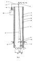
- the inventive electrostatic filter system according to Fig. 2 essentially comprises a chimney 9 and a spray electrode 11.
- the spray electrode is advantageously designed as a rod electrode 11, but may for example also be formed as a chain electrode.
- the rod electrode 11 is advantageously arranged in the center of the exhaust passage 13 of the chimney 9 as parallel as possible to the longitudinal axis 25 of the exhaust passage 13.
- the rod electrode 11 is hingedly or optionally rigidly attached to a suspension 15 of a holder arm 17.
- the holder arm 17 is optionally flexibly secured in an insulator 19.
- the holder arm 17 may be fastened to the insulator 19 via a plug and / or screw connection 21.
- the insulator in turn, is expediently For example, outside the fireplace 9 attached.
- the holder arm 17 extends with the suspension 15 in the exhaust passage 13, in particular such that the suspension 15 is positioned as centrally as possible in the exhaust passage 13 from its walls 29 spaced.
- the attached rod electrode 11 is aligned due to its own weight along the longitudinal axis 25 of the exhaust passage 13 from. As indicated above, however, the dead weight of the electrode 11 is not necessarily sufficient to keep the spray electrode 11 stable under operating voltage and centrally in the exhaust gas duct 13.
- stabilization is achieved by a magnet arrangement attached to the spray electrode 11 and the chimney 9.
- a first, central magnet 31 (which may be composed of a single magnet or a plurality of partial magnets) is attached to the spray electrode 11.
- a plurality of peripheral magnets 33 surrounding the first central magnet 31 are fixed to a chimney wall (each peripheral magnet may also be composed of a single magnet or a plurality of part magnets).
- a plurality of at least three peripheral magnets 33 are advantageous. Shown here is a preferred plurality of 12 peripheral magnets 33.
- the peripheral magnets 33 are expediently provided on the circumference of the chimney 9 on its wall, for example on its inner wall 29 or preferably on its outer wall 35 , distributed.
- All the magnets, all the peripheral magnets 33 as well as the central magnet 31, are arranged so as to repel each other.
- bar magnets are preferably used whose north-south axes are aligned parallel and rectified.
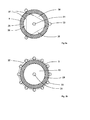
- the distribution of the peripheral magnets 33 is such that a closed imaginary connecting line 37 (see FIG Fig. 3a and Fig. 3b ), which magnetically connects the magnets 33 of said plurality, around the first magnet 31 and thus around the suspended spray electrode 11 (especially even if it is not under high voltage).
- the imaginary connecting lines form the shortest connections between two repelling magnets 33.
- a third magnet is repelled with respect to such an imaginary line, since the repulsive forces are greater at an intersection with this line than at any other point of a line (or area), which intersects the imaginary line vertically.
- the entire imaginary connecting line 37 extends outside the exhaust duct 13, as in FIG Fig. 3b shown. This has the advantage that in the exhaust passage 13, which is bounded by the inner wall 29, no imaginary pockets 38 with radially outwardly decreasing magnetic force between the inner wall 29 and imaginary connecting line 37 may exist. Because there is the possibility that the central magnets 31 could be pressed with the spray electrode 11 in such an imaginary pocket 38 and thereby optionally against the inner wall 29 of the chimney 9, which would most likely lead to a short circuit.
- the magnets 31, 33 are frictionally engaged with their respective carrier, i. the spray magnet 11 or the chimney 9 connected.
- the peripheral magnets 33 are regularly distributed, i. all the magnets 33 are equidistant from the central magnet 31, and all the peripheral magnets 33 are approximately equidistant from one another. This arrangement is particularly advantageous when the peripheral magnets 33 generate approximately equal magnetic fields.
- a draft weight 27 may be attached to the spray electrode 11 in addition to the central magnet.
- This draw weight 27 can further enhance the stretch and alignment of the spray electrode 11 due to its weight.
- Such a draw weight 27 is advantageously arranged below the central magnet 31.
- the peripheral magnets 33 and optionally the central magnet 31 may be selected from the group of permanent magnets. If necessary, a high-temperature magnet can be used as the draw weight. This is particularly useful at high operating temperatures in the exhaust duct 13.
- each magnet 31, 33 in a protective cover in particular in a hermetically sealed protective cover, be used.
- Protective covers can be attached directly to the fireplace or the rod electrode, eg by screwing or welding.
- Protective covers may alternatively be attached to a strap or cuff. In which case the belt or the cuff is fastened to the chimney 9, preferably to the outer wall 35 of the chimney 9.
- the magnetic ring or magnet ring (magnets 33), which is preferably mounted outside the chimney pipe, repulsive acts on the central magnet 31, thus is held by repulsive forces of the central magnet 31 in the center of the magnetic ring and thus centrally in the exhaust passage 13 and optionally positioned.
- An electrical high voltage supply 23 supplies the electrical voltage for the rod electrode 11.
- at least the inner wall 29 of the chimney 9 is earthed.
- the central magnet 31 has the tendency to deflect laterally, possibly to rotate about an axis of rotation (in particular to the suspension 15). If necessary, the magnet can be kept stable by means of an additional weight, ie the above-mentioned draft weight 27.
- Fig. 4 is the exhaust duct of FIG. 2 shown with deflected electrode. Shown are approximately the forces acting due to weight, magnetic repulsion and deflection. The dead weight of the spray electrode 11 and the additional draw weight 27 cause the gravitational force F g . Due to weight and deflection results in a first portion of a restoring force F gr (in which case the weight of the magnets should be considered). In addition, magnetic forces act here. In a system with a low deflection angle, it can be assumed for simplicity that the magnetic forces act approximately in the horizontal direction. In the given embodiment, as stated above, the magnets are mounted repellent against each other.
- FIG. 9 As can be seen, a long electrode (eg 10 m) can reach an unstable state after a certain deflection, which in turn leads to a short circuit. According to the simulated situation in FIG. 9 is from a deflection of about 6.5 cm, the system unstable (this can be seen in that the sign of the total calculated torque at the said deflection of about 6.5 cm changes).
- the FIGS. 10 and 11 now show the torques occurring, taking into account the magnetic centering. As additional torque, the magnetic torque was inserted. The sign here is the same as for Torque of weight (draft weight 27) and opposite to the electrostatic force. Due to the summation of all torques, there is no change of sign when deflecting to one side over the entire possible deflection range. This means that the electrode 11 experiences a centering force or centering torque to the center over the entire deflection range.
- the magnetic restoring forces F m can clearly exceed the effect of the restoring forces F gr established on the weight with relatively little deflection.
- the positioning of a long discharge electrode 11 can be significantly improved by the additional use of repelling magnets. Vibrations and short circuit can thus be effectively suppressed or prevented.
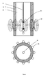
- Fig. 5 is an electrostatic filter system with an alternative magnet arrangement comprising a first magnet group 39 and a second magnet group 40 shown.
- a first magnet group 39 and a second magnet group 40 shown.
- central and peripheral magnets 41, 43 of a second magnet group 40 are fixed to the outer chimney wall 35 at at least one intermediate region of the rod electrode 11 and at approximately the same height.
- a second magnet group 40 or further magnet groups distributed over the length of the spray electrode 11 can further contribute to the stabilization of the spray electrode 11.
- Each of these magnet groups 39 and 40 is thus composed of first and second magnetic elements and each first and second magnetic element of a group is arranged at approximately the same height on the chimney 9.
- Central and peripheral magnets can be designed as bar magnets, see Fig. 2 . 5 or enlarged Fig. 6 , Optionally, however, it is also possible to use magnets of a different design.
- horseshoe magnets 45 can be demonstrated on the periphery. As with the central bar magnet 31, the effective poles of the horseshoe magnet 45 are aligned in a vertical axis, with the same sense of direction as the central bar magnet. Horseshoe magnets 45 have the advantage that their magnetic field lines (especially when used in peripheral position) can be directed mainly into the exhaust gas interior.
- the centering of the electrode can alternatively be done via one or more magnetic rings.
- one or more magnetic rings are advantageously placed around the chimney, in particular at the level of a central magnet or a plurality of central magnets, which are attached to the spray electrode.
Landscapes
- Electrostatic Separation (AREA)
Applications Claiming Priority (1)
| Application Number | Priority Date | Filing Date | Title |
|---|---|---|---|
| CH01253/11A CH705334A2 (de) | 2011-07-27 | 2011-07-27 | Zentrierung einer Hochspannungselektrode durch magnetische Kräfte. |
Publications (3)
| Publication Number | Publication Date |
|---|---|
| EP2551018A2 true EP2551018A2 (fr) | 2013-01-30 |
| EP2551018A3 EP2551018A3 (fr) | 2014-08-20 |
| EP2551018B1 EP2551018B1 (fr) | 2018-01-31 |
Family
ID=47018019
Family Applications (1)
| Application Number | Title | Priority Date | Filing Date |
|---|---|---|---|
| EP12178046.4A Active EP2551018B1 (fr) | 2011-07-27 | 2012-07-26 | Centrage d'une électrode sous haute tension par force magnétique |
Country Status (2)
| Country | Link |
|---|---|
| EP (1) | EP2551018B1 (fr) |
| CH (1) | CH705334A2 (fr) |
Cited By (5)
| Publication number | Priority date | Publication date | Assignee | Title |
|---|---|---|---|---|
| WO2014145272A1 (fr) * | 2013-03-15 | 2014-09-18 | O'brian Michael A | Précipitateur électrostatique de collecte d'huile |
| CN107803275A (zh) * | 2017-12-13 | 2018-03-16 | 中冶焦耐(大连)工程技术有限公司 | 一种电晕线磁力定位装置 |
| EP3025785B1 (fr) * | 2014-11-25 | 2022-01-26 | SMS group GmbH | Dispositif et procédé de nettoyage de gaz de fumée d'une installation métallurgique |
| EP4414080A1 (fr) * | 2023-02-10 | 2024-08-14 | exodraft a/s | Unité de précipitation électrostatique avec plaque de protection thermique et moyens de refroidissement par convection |
| EP4414081A1 (fr) * | 2023-02-10 | 2024-08-14 | exodraft a/s | Système comprenant un ensemble d'électrodes de décharge et unité de précipitateur électrostatique comprenant un tel système |
Citations (1)
| Publication number | Priority date | Publication date | Assignee | Title |
|---|---|---|---|---|
| EP0397208A2 (fr) | 1989-05-12 | 1990-11-14 | FRITZ EGGER GESELLSCHAFT m.b.H. | Séparateur électrostatique pour la purification des gaz |
Family Cites Families (3)
| Publication number | Priority date | Publication date | Assignee | Title |
|---|---|---|---|---|
| CA1159773A (fr) * | 1981-09-30 | 1984-01-03 | George Drzewiecki | Separateur par voie humide avec plaques hexagonales de captage imbriquees, dispositif magnetique d'alignement et secoueur de decolmatage |
| FR2575675B3 (fr) * | 1984-05-30 | 1987-02-06 | Bacot Dominique | Filtre electrostatique en voie humide |
| US5714063A (en) * | 1996-05-28 | 1998-02-03 | Brunsting; William J. | Apparatus for the removal of ferrous particles from liquids |
-
2011
- 2011-07-27 CH CH01253/11A patent/CH705334A2/de not_active Application Discontinuation
-
2012
- 2012-07-26 EP EP12178046.4A patent/EP2551018B1/fr active Active
Patent Citations (1)
| Publication number | Priority date | Publication date | Assignee | Title |
|---|---|---|---|---|
| EP0397208A2 (fr) | 1989-05-12 | 1990-11-14 | FRITZ EGGER GESELLSCHAFT m.b.H. | Séparateur électrostatique pour la purification des gaz |
Cited By (5)
| Publication number | Priority date | Publication date | Assignee | Title |
|---|---|---|---|---|
| WO2014145272A1 (fr) * | 2013-03-15 | 2014-09-18 | O'brian Michael A | Précipitateur électrostatique de collecte d'huile |
| EP3025785B1 (fr) * | 2014-11-25 | 2022-01-26 | SMS group GmbH | Dispositif et procédé de nettoyage de gaz de fumée d'une installation métallurgique |
| CN107803275A (zh) * | 2017-12-13 | 2018-03-16 | 中冶焦耐(大连)工程技术有限公司 | 一种电晕线磁力定位装置 |
| EP4414080A1 (fr) * | 2023-02-10 | 2024-08-14 | exodraft a/s | Unité de précipitation électrostatique avec plaque de protection thermique et moyens de refroidissement par convection |
| EP4414081A1 (fr) * | 2023-02-10 | 2024-08-14 | exodraft a/s | Système comprenant un ensemble d'électrodes de décharge et unité de précipitateur électrostatique comprenant un tel système |
Also Published As
| Publication number | Publication date |
|---|---|
| EP2551018A3 (fr) | 2014-08-20 |
| CH705334A2 (de) | 2013-01-31 |
| EP2551018B1 (fr) | 2018-01-31 |
Similar Documents
| Publication | Publication Date | Title |
|---|---|---|
| DE3532978C1 (de) | Elektrodenanordnung fuer Koronaentladungen | |
| EP2244834B1 (fr) | Séparateur électrostatique | |
| EP2551018B1 (fr) | Centrage d'une électrode sous haute tension par force magnétique | |
| EP2712678B1 (fr) | Support pour une électrode et installation de filtrage de poussières électrostatiques fines comprenant ce support | |
| DD297868A5 (de) | Koronaentladungsanordnung mit verbesserter beseitigung von durch die koronaentladung entstehendnen schaedlichen substanzen | |
| DD257590A5 (de) | Anordnung zur erzeugung einer elektrischen koronaentladung in der luft | |
| EP1361927A1 (fr) | Depoussiereur electrostatique a tubes de filtration integres | |
| DE102017114638B4 (de) | Elektrostatischer Abscheider und Verfahren zur elektrostatischen Abscheidung von Stoffen aus einem Abgasstrom | |
| WO2006125485A1 (fr) | Etage d'ionisation electrostatique en voie humide dans un dispositif de separation electrostatique | |
| DE102004039124B4 (de) | Elektrofilter für eine Feuerungsanlage | |
| DE2438670B2 (de) | Elektrischer Staubabscheider | |
| AT504902B1 (de) | Elektrofilter für eine feuerungsanlage | |
| WO2007033772A1 (fr) | Etage d'ionisation electrostatique dans un dispositif de precipitation | |
| DE2555395A1 (de) | Elektrostatischer ausfaeller zum reinigen von mit partikeln beladenem gas | |
| AT506397B1 (de) | Abscheideeinrichtung für partikel | |
| EP2266702B1 (fr) | Séparateur électrostatique destiné au nettoyage de gaz de fumée avec un champ de verrouillage électrique | |
| EP2284442A2 (fr) | Séparateur électrostatique et système de chauffage | |
| EP2108457B1 (fr) | Système de cheminée avec précipitateur électrostatique | |
| EP2251088B1 (fr) | Séparateur électrostatique et système de chauffage | |
| DE102007056696B3 (de) | Elektrostatischer Abscheider mit Partikelabweisemittel, Heizungssystem und Verfahren zum Betrieb | |
| EP3025785B1 (fr) | Dispositif et procédé de nettoyage de gaz de fumée d'une installation métallurgique | |
| CN203803644U (zh) | 磁偏转高压脉冲除尘净化器 | |
| DE102006009765B4 (de) | Röhrenelektrofilter | |
| DE202017107784U1 (de) | Luftreiniger zum Reinigen eines Luftstroms | |
| DE102017003855A1 (de) | Vorrichtung zur Erhöhung der Stabilität am unteren Erdungsring bei Elektrofiltern |
Legal Events
| Date | Code | Title | Description |
|---|---|---|---|
| PUAI | Public reference made under article 153(3) epc to a published international application that has entered the european phase |
Free format text: ORIGINAL CODE: 0009012 |
|
| AK | Designated contracting states |
Kind code of ref document: A2 Designated state(s): AL AT BE BG CH CY CZ DE DK EE ES FI FR GB GR HR HU IE IS IT LI LT LU LV MC MK MT NL NO PL PT RO RS SE SI SK SM TR |
|
| AX | Request for extension of the european patent |
Extension state: BA ME |
|
| PUAL | Search report despatched |
Free format text: ORIGINAL CODE: 0009013 |
|
| AK | Designated contracting states |
Kind code of ref document: A3 Designated state(s): AL AT BE BG CH CY CZ DE DK EE ES FI FR GB GR HR HU IE IS IT LI LT LU LV MC MK MT NL NO PL PT RO RS SE SI SK SM TR |
|
| AX | Request for extension of the european patent |
Extension state: BA ME |
|
| RIC1 | Information provided on ipc code assigned before grant |
Ipc: B03C 3/41 20060101ALI20140714BHEP Ipc: B03C 3/70 20060101ALI20140714BHEP Ipc: B03C 3/49 20060101ALI20140714BHEP Ipc: B03C 3/86 20060101AFI20140714BHEP |
|
| 17P | Request for examination filed |
Effective date: 20150218 |
|
| RBV | Designated contracting states (corrected) |
Designated state(s): AL AT BE BG CH CY CZ DE DK EE ES FI FR GB GR HR HU IE IS IT LI LT LU LV MC MK MT NL NO PL PT RO RS SE SI SK SM TR |
|
| GRAP | Despatch of communication of intention to grant a patent |
Free format text: ORIGINAL CODE: EPIDOSNIGR1 |
|
| INTG | Intention to grant announced |
Effective date: 20170905 |
|
| GRAS | Grant fee paid |
Free format text: ORIGINAL CODE: EPIDOSNIGR3 |
|
| GRAA | (expected) grant |
Free format text: ORIGINAL CODE: 0009210 |
|
| RAP1 | Party data changed (applicant data changed or rights of an application transferred) |
Owner name: MUELLER, BEAT Owner name: JUD, DANIEL |
|
| RIN1 | Information on inventor provided before grant (corrected) |
Inventor name: MUELLER, BEAT Inventor name: JUD, DANIEL |
|
| AK | Designated contracting states |
Kind code of ref document: B1 Designated state(s): AL AT BE BG CH CY CZ DE DK EE ES FI FR GB GR HR HU IE IS IT LI LT LU LV MC MK MT NL NO PL PT RO RS SE SI SK SM TR |
|
| REG | Reference to a national code |
Ref country code: GB Ref legal event code: FG4D Free format text: NOT ENGLISH Ref country code: CH Ref legal event code: EP |
|
| REG | Reference to a national code |
Ref country code: AT Ref legal event code: REF Ref document number: 966851 Country of ref document: AT Kind code of ref document: T Effective date: 20180215 |
|
| REG | Reference to a national code |
Ref country code: IE Ref legal event code: FG4D Free format text: LANGUAGE OF EP DOCUMENT: GERMAN |
|
| REG | Reference to a national code |
Ref country code: DE Ref legal event code: R096 Ref document number: 502012012093 Country of ref document: DE |
|
| REG | Reference to a national code |
Ref country code: CH Ref legal event code: NV Representative=s name: RIEDERER HASLER AND PARTNER PATENTANWAELTE AG, CH |
|
| REG | Reference to a national code |
Ref country code: NL Ref legal event code: MP Effective date: 20180131 |
|
| REG | Reference to a national code |
Ref country code: LT Ref legal event code: MG4D |
|
| PG25 | Lapsed in a contracting state [announced via postgrant information from national office to epo] |
Ref country code: ES Free format text: LAPSE BECAUSE OF FAILURE TO SUBMIT A TRANSLATION OF THE DESCRIPTION OR TO PAY THE FEE WITHIN THE PRESCRIBED TIME-LIMIT Effective date: 20180131 Ref country code: NL Free format text: LAPSE BECAUSE OF FAILURE TO SUBMIT A TRANSLATION OF THE DESCRIPTION OR TO PAY THE FEE WITHIN THE PRESCRIBED TIME-LIMIT Effective date: 20180131 Ref country code: FI Free format text: LAPSE BECAUSE OF FAILURE TO SUBMIT A TRANSLATION OF THE DESCRIPTION OR TO PAY THE FEE WITHIN THE PRESCRIBED TIME-LIMIT Effective date: 20180131 Ref country code: LT Free format text: LAPSE BECAUSE OF FAILURE TO SUBMIT A TRANSLATION OF THE DESCRIPTION OR TO PAY THE FEE WITHIN THE PRESCRIBED TIME-LIMIT Effective date: 20180131 Ref country code: NO Free format text: LAPSE BECAUSE OF FAILURE TO SUBMIT A TRANSLATION OF THE DESCRIPTION OR TO PAY THE FEE WITHIN THE PRESCRIBED TIME-LIMIT Effective date: 20180430 Ref country code: HR Free format text: LAPSE BECAUSE OF FAILURE TO SUBMIT A TRANSLATION OF THE DESCRIPTION OR TO PAY THE FEE WITHIN THE PRESCRIBED TIME-LIMIT Effective date: 20180131 |
|
| PG25 | Lapsed in a contracting state [announced via postgrant information from national office to epo] |
Ref country code: BG Free format text: LAPSE BECAUSE OF FAILURE TO SUBMIT A TRANSLATION OF THE DESCRIPTION OR TO PAY THE FEE WITHIN THE PRESCRIBED TIME-LIMIT Effective date: 20180430 Ref country code: GR Free format text: LAPSE BECAUSE OF FAILURE TO SUBMIT A TRANSLATION OF THE DESCRIPTION OR TO PAY THE FEE WITHIN THE PRESCRIBED TIME-LIMIT Effective date: 20180501 Ref country code: RS Free format text: LAPSE BECAUSE OF FAILURE TO SUBMIT A TRANSLATION OF THE DESCRIPTION OR TO PAY THE FEE WITHIN THE PRESCRIBED TIME-LIMIT Effective date: 20180131 Ref country code: LV Free format text: LAPSE BECAUSE OF FAILURE TO SUBMIT A TRANSLATION OF THE DESCRIPTION OR TO PAY THE FEE WITHIN THE PRESCRIBED TIME-LIMIT Effective date: 20180131 Ref country code: SE Free format text: LAPSE BECAUSE OF FAILURE TO SUBMIT A TRANSLATION OF THE DESCRIPTION OR TO PAY THE FEE WITHIN THE PRESCRIBED TIME-LIMIT Effective date: 20180131 Ref country code: IS Free format text: LAPSE BECAUSE OF FAILURE TO SUBMIT A TRANSLATION OF THE DESCRIPTION OR TO PAY THE FEE WITHIN THE PRESCRIBED TIME-LIMIT Effective date: 20180531 Ref country code: PL Free format text: LAPSE BECAUSE OF FAILURE TO SUBMIT A TRANSLATION OF THE DESCRIPTION OR TO PAY THE FEE WITHIN THE PRESCRIBED TIME-LIMIT Effective date: 20180131 |
|
| PG25 | Lapsed in a contracting state [announced via postgrant information from national office to epo] |
Ref country code: MT Free format text: LAPSE BECAUSE OF FAILURE TO SUBMIT A TRANSLATION OF THE DESCRIPTION OR TO PAY THE FEE WITHIN THE PRESCRIBED TIME-LIMIT Effective date: 20180131 |
|
| PG25 | Lapsed in a contracting state [announced via postgrant information from national office to epo] |
Ref country code: RO Free format text: LAPSE BECAUSE OF FAILURE TO SUBMIT A TRANSLATION OF THE DESCRIPTION OR TO PAY THE FEE WITHIN THE PRESCRIBED TIME-LIMIT Effective date: 20180131 Ref country code: IT Free format text: LAPSE BECAUSE OF FAILURE TO SUBMIT A TRANSLATION OF THE DESCRIPTION OR TO PAY THE FEE WITHIN THE PRESCRIBED TIME-LIMIT Effective date: 20180131 Ref country code: EE Free format text: LAPSE BECAUSE OF FAILURE TO SUBMIT A TRANSLATION OF THE DESCRIPTION OR TO PAY THE FEE WITHIN THE PRESCRIBED TIME-LIMIT Effective date: 20180131 Ref country code: AL Free format text: LAPSE BECAUSE OF FAILURE TO SUBMIT A TRANSLATION OF THE DESCRIPTION OR TO PAY THE FEE WITHIN THE PRESCRIBED TIME-LIMIT Effective date: 20180131 |
|
| REG | Reference to a national code |
Ref country code: DE Ref legal event code: R097 Ref document number: 502012012093 Country of ref document: DE |
|
| PG25 | Lapsed in a contracting state [announced via postgrant information from national office to epo] |
Ref country code: DK Free format text: LAPSE BECAUSE OF FAILURE TO SUBMIT A TRANSLATION OF THE DESCRIPTION OR TO PAY THE FEE WITHIN THE PRESCRIBED TIME-LIMIT Effective date: 20180131 Ref country code: SM Free format text: LAPSE BECAUSE OF FAILURE TO SUBMIT A TRANSLATION OF THE DESCRIPTION OR TO PAY THE FEE WITHIN THE PRESCRIBED TIME-LIMIT Effective date: 20180131 Ref country code: CZ Free format text: LAPSE BECAUSE OF FAILURE TO SUBMIT A TRANSLATION OF THE DESCRIPTION OR TO PAY THE FEE WITHIN THE PRESCRIBED TIME-LIMIT Effective date: 20180131 Ref country code: SK Free format text: LAPSE BECAUSE OF FAILURE TO SUBMIT A TRANSLATION OF THE DESCRIPTION OR TO PAY THE FEE WITHIN THE PRESCRIBED TIME-LIMIT Effective date: 20180131 |
|
| PLBE | No opposition filed within time limit |
Free format text: ORIGINAL CODE: 0009261 |
|
| STAA | Information on the status of an ep patent application or granted ep patent |
Free format text: STATUS: NO OPPOSITION FILED WITHIN TIME LIMIT |
|
| 26N | No opposition filed |
Effective date: 20181102 |
|
| PG25 | Lapsed in a contracting state [announced via postgrant information from national office to epo] |
Ref country code: SI Free format text: LAPSE BECAUSE OF FAILURE TO SUBMIT A TRANSLATION OF THE DESCRIPTION OR TO PAY THE FEE WITHIN THE PRESCRIBED TIME-LIMIT Effective date: 20180131 |
|
| GBPC | Gb: european patent ceased through non-payment of renewal fee |
Effective date: 20180726 |
|
| PG25 | Lapsed in a contracting state [announced via postgrant information from national office to epo] |
Ref country code: LU Free format text: LAPSE BECAUSE OF NON-PAYMENT OF DUE FEES Effective date: 20180726 Ref country code: MC Free format text: LAPSE BECAUSE OF FAILURE TO SUBMIT A TRANSLATION OF THE DESCRIPTION OR TO PAY THE FEE WITHIN THE PRESCRIBED TIME-LIMIT Effective date: 20180131 |
|
| REG | Reference to a national code |
Ref country code: BE Ref legal event code: MM Effective date: 20180731 |
|
| REG | Reference to a national code |
Ref country code: IE Ref legal event code: MM4A |
|
| PG25 | Lapsed in a contracting state [announced via postgrant information from national office to epo] |
Ref country code: GB Free format text: LAPSE BECAUSE OF NON-PAYMENT OF DUE FEES Effective date: 20180726 Ref country code: FR Free format text: LAPSE BECAUSE OF NON-PAYMENT OF DUE FEES Effective date: 20180731 Ref country code: IE Free format text: LAPSE BECAUSE OF NON-PAYMENT OF DUE FEES Effective date: 20180726 |
|
| PG25 | Lapsed in a contracting state [announced via postgrant information from national office to epo] |
Ref country code: BE Free format text: LAPSE BECAUSE OF NON-PAYMENT OF DUE FEES Effective date: 20180731 |
|
| PG25 | Lapsed in a contracting state [announced via postgrant information from national office to epo] |
Ref country code: TR Free format text: LAPSE BECAUSE OF FAILURE TO SUBMIT A TRANSLATION OF THE DESCRIPTION OR TO PAY THE FEE WITHIN THE PRESCRIBED TIME-LIMIT Effective date: 20180131 |
|
| PG25 | Lapsed in a contracting state [announced via postgrant information from national office to epo] |
Ref country code: HU Free format text: LAPSE BECAUSE OF FAILURE TO SUBMIT A TRANSLATION OF THE DESCRIPTION OR TO PAY THE FEE WITHIN THE PRESCRIBED TIME-LIMIT; INVALID AB INITIO Effective date: 20120726 Ref country code: PT Free format text: LAPSE BECAUSE OF FAILURE TO SUBMIT A TRANSLATION OF THE DESCRIPTION OR TO PAY THE FEE WITHIN THE PRESCRIBED TIME-LIMIT Effective date: 20180131 |
|
| PG25 | Lapsed in a contracting state [announced via postgrant information from national office to epo] |
Ref country code: CY Free format text: LAPSE BECAUSE OF FAILURE TO SUBMIT A TRANSLATION OF THE DESCRIPTION OR TO PAY THE FEE WITHIN THE PRESCRIBED TIME-LIMIT Effective date: 20180131 Ref country code: MK Free format text: LAPSE BECAUSE OF NON-PAYMENT OF DUE FEES Effective date: 20180131 |
|
| PGFP | Annual fee paid to national office [announced via postgrant information from national office to epo] |
Ref country code: CH Payment date: 20230802 Year of fee payment: 12 Ref country code: AT Payment date: 20230720 Year of fee payment: 12 |
|
| PGFP | Annual fee paid to national office [announced via postgrant information from national office to epo] |
Ref country code: DE Payment date: 20230719 Year of fee payment: 12 |
|
| REG | Reference to a national code |
Ref country code: CH Ref legal event code: PK Free format text: BERICHTIGUNGEN |
|
| REG | Reference to a national code |
Ref country code: DE Ref legal event code: R119 Ref document number: 502012012093 Country of ref document: DE |
|
| REG | Reference to a national code |
Ref country code: CH Ref legal event code: PL |
|
| REG | Reference to a national code |
Ref country code: AT Ref legal event code: MM01 Ref document number: 966851 Country of ref document: AT Kind code of ref document: T Effective date: 20240726 |
|
| PG25 | Lapsed in a contracting state [announced via postgrant information from national office to epo] |
Ref country code: DE Free format text: LAPSE BECAUSE OF NON-PAYMENT OF DUE FEES Effective date: 20250201 |
|
| PG25 | Lapsed in a contracting state [announced via postgrant information from national office to epo] |
Ref country code: CH Free format text: LAPSE BECAUSE OF NON-PAYMENT OF DUE FEES Effective date: 20240731 Ref country code: AT Free format text: LAPSE BECAUSE OF NON-PAYMENT OF DUE FEES Effective date: 20240726 |