EP2551027B1 - Dispositif et procédé destinés à l'étirage de tuyaux à soudure longitudinale - Google Patents
Dispositif et procédé destinés à l'étirage de tuyaux à soudure longitudinale Download PDFInfo
- Publication number
- EP2551027B1 EP2551027B1 EP12177475.6A EP12177475A EP2551027B1 EP 2551027 B1 EP2551027 B1 EP 2551027B1 EP 12177475 A EP12177475 A EP 12177475A EP 2551027 B1 EP2551027 B1 EP 2551027B1
- Authority
- EP
- European Patent Office
- Prior art keywords
- tube
- lubricant
- station
- stage
- inner mandrel
- Prior art date
- Legal status (The legal status is an assumption and is not a legal conclusion. Google has not performed a legal analysis and makes no representation as to the accuracy of the status listed.)
- Not-in-force
Links
Images
Classifications
-
- B—PERFORMING OPERATIONS; TRANSPORTING
- B21—MECHANICAL METAL-WORKING WITHOUT ESSENTIALLY REMOVING MATERIAL; PUNCHING METAL
- B21C—MANUFACTURE OF METAL SHEETS, WIRE, RODS, TUBES, PROFILES OR LIKE SEMI-MANUFACTURED PRODUCTS OTHERWISE THAN BY ROLLING; AUXILIARY OPERATIONS USED IN CONNECTION WITH METAL-WORKING WITHOUT ESSENTIALLY REMOVING MATERIAL
- B21C1/00—Manufacture of metal sheets, wire, rods, tubes or like semi-manufactured products by drawing
- B21C1/16—Metal drawing by machines or apparatus in which the drawing action is effected by means other than drums, e.g. by a longitudinally-moved carriage pulling or pushing the work or stock for making metal sheets, rods or tubes
- B21C1/22—Metal drawing by machines or apparatus in which the drawing action is effected by means other than drums, e.g. by a longitudinally-moved carriage pulling or pushing the work or stock for making metal sheets, rods or tubes specially adapted for making tubular articles
- B21C1/24—Metal drawing by machines or apparatus in which the drawing action is effected by means other than drums, e.g. by a longitudinally-moved carriage pulling or pushing the work or stock for making metal sheets, rods or tubes specially adapted for making tubular articles by means of mandrels
-
- B—PERFORMING OPERATIONS; TRANSPORTING
- B21—MECHANICAL METAL-WORKING WITHOUT ESSENTIALLY REMOVING MATERIAL; PUNCHING METAL
- B21C—MANUFACTURE OF METAL SHEETS, WIRE, RODS, TUBES, PROFILES OR LIKE SEMI-MANUFACTURED PRODUCTS OTHERWISE THAN BY ROLLING; AUXILIARY OPERATIONS USED IN CONNECTION WITH METAL-WORKING WITHOUT ESSENTIALLY REMOVING MATERIAL
- B21C37/00—Manufacture of metal sheets, rods, wire, tubes, profiles or like semi-manufactured products, not otherwise provided for; Manufacture of tubes of special shape
- B21C37/06—Manufacture of metal sheets, rods, wire, tubes, profiles or like semi-manufactured products, not otherwise provided for; Manufacture of tubes of special shape of tubes or metal hoses; Combined procedures for making tubes, e.g. for making multi-wall tubes
- B21C37/08—Making tubes with welded or soldered seams
- B21C37/0807—Tube treating or manipulating combined with, or specially adapted for use in connection with tube making machines, e.g. drawing-off devices, cutting-off
- B21C37/0811—Tube treating or manipulating combined with, or specially adapted for use in connection with tube making machines, e.g. drawing-off devices, cutting-off removing or treating the weld bead
-
- B—PERFORMING OPERATIONS; TRANSPORTING
- B21—MECHANICAL METAL-WORKING WITHOUT ESSENTIALLY REMOVING MATERIAL; PUNCHING METAL
- B21C—MANUFACTURE OF METAL SHEETS, WIRE, RODS, TUBES, PROFILES OR LIKE SEMI-MANUFACTURED PRODUCTS OTHERWISE THAN BY ROLLING; AUXILIARY OPERATIONS USED IN CONNECTION WITH METAL-WORKING WITHOUT ESSENTIALLY REMOVING MATERIAL
- B21C9/00—Cooling, heating or lubricating drawing material
Definitions
- the invention relates to a device for drawing longitudinally welded pipes according to the features in the preamble of patent claim 1 and a corresponding method according to the features in the preamble of claim 5.
- the DE 23 54 161 A1 discloses a method and a system for the continuous production of pipes, in which lubricant is introduced via a lance into a space in front of a drawing mandrel. This space is additionally limited by a plastic or hard rubber sealing plate. As a result, the lubricant for the drawing mandrel should not mix with a cooling emulsion an upstream pipe welding plant.
- the sealing plate is located just before the drawing mandrel and thus behind a cooling station, which also belongs to the system described. Lubricant is introduced behind the cooling station.
- the JP 59 097 724 A discloses a device for drawing longitudinally welded tubes with flying inner mandrel and rotating die. The rotational movement of the die is to be achieved that reduce the pulling forces.
- the aim is to improve the production of pipes (in line) without inner weld supernatant according to EN DIN 10305-2.
- Claim 1 relates to a device for pulling longitudinally welded pipes.
- the apparatus initially comprises a tube forming station, which is intended to form a tube from a strip material.
- the molded tube is welded in a welding station to form a tube.
- the opposing longitudinal edges of the strip material can be inductively welded together.
- the welding station is adjoined by a cooling station, in which the tube heated by the welding process is cooled and subsequently fed to a plurality of drawing stages connected in series, which are provided for diameter reduction. There are at least two draw levels provided.
- a drawing tool is provided which comprises a die and a flying inner mandrel. This inner mandrel is lubricated by supplying a lubricant.
- a lubricant lance brings the lubricant into a region in which the strip material is already welded to form a tube.
- the lubricant lance extends through the welding station in the production direction of the production line, with the region of the lubricant introduction lying in or behind the cooling station.
- the area of the lubricant introduction coincides in particular with an end-side opening in the lubricant lance.
- the lubricant lance is therefore already arranged in the region of the tube forming station, before the strip material is welded to the tube, opening into the tube and extends relatively deep into the tube.
- the lubricant lance conveys the lubricant so far into the pipe to be manufactured that there is a sufficient distance from the welding station.
- a supply of the lubricant in the area of the welding point or just behind it, would lead to smoke and could even lead to the ignition of the drawn oil used as a lubricant. This should / should therefore be avoided.
- the cooling station is in particular a water bath which cools the outside and thus also the inside of the tube.
- the oil temperature can be kept so low that it does not come to a disturbing smoke.
- the oil temperature is kept below 100 ° C. The exact temperature, however, depends on the grade and the specific viscosity of the lubricant.
- the lubricant lance preferably extends in the direction of production into the half of the cooling station facing away from the welding station. This ensures that the temperature on the inner walls of the longitudinally welded pipe has been reduced so far that no smoke is generated.
- the first drawing stage to be passed may be a hollow pulling station for reducing the pipe diameter, the subsequent further drawing stage being designed to smooth a weld seam of the pipe on the inside, under the influence of the lubricating inner flying mandrel. Finally, in a further drawing stage in a pure hoist, so no inner pull with mandrel, a reduction to final dimensions.
- the first drawing stage thus serves for tube rounding.
- the first drawing stage includes not only a drawing tool, but also a first tube drawing drum around which the tube is passed. Due to the fact that the first drawing stage is a pure hollow draft for tube rounding, there is the effect that a draft on the pipe circumference is created by the train without intermediate annealing. This indentation results from the different drawing behavior of the hard longitudinal seam compared to the soft base material. This results in the subsequent train with internal mandrel the possibility einzuglätten the inwardly projecting longitudinal seam. In the rebound stage with internal mandrel, therefore, a reduction of the pipe wall preferably does not take place, but only a smoothing.
- the shaping of the inner mandrel by the inner mandrel takes place under the influence of the inner mandrel, but ultimately by the hydrodynamic lubrication, which is ensured by a permanent lubricant supply.
- the internal mandrel used is adapted to the requirements of hydrodynamic lubrication with regard to its geometry.
- the lubricant entrained by the drawing material due to its friction is at such high pressures in the specially designed inner mandrel Annular gap between the inner tube surface and the inner mandrel brought so that there is a flattening of the longitudinal weld.
- an inner mandrel is used, which is made of a suitable hard material, such as carbide, diamond, ceramic, tool steel.
- the inner mandrel can be provided with a suitable coating which specifically counteracts the wear in the start-up process characterized by mixed friction.
- the coating is capable of overcoming the range of mixed friction without negative buildup or abrasion to prevent the formation of grooves on the inner wall.
- the inner mandrel is in particular a carbide mandrel. It is also possible to use suitable steels which are extremely readily mouldable (composition of EN 10305). Special thermal finish annealing treatment can be used to meet mechanical characteristics that comply with this standard. These mandrels have a high stability.
- mandrel length refers to the outer diameter of the tube of about 15 mm.
- the inner mandrel is preferably mirror-symmetrical, so that it can cooperate by simply turning both sides of the die and thus is even longer usable.
- the inner mandrel already in the first drawing stage.
- the first drawing stage is therefore preceded by a calibration stage, which ensures the rounding of the longitudinally welded pipe.
- the reduction to the final dimension takes place by means of a purely hollow draw.
- the process step of annealing before reducing the tube On final dimension can be omitted, making the manufacturing process is significantly cheaper overall.
- the device for producing the cold-drawn tubes is thus less expensive to implement.
- the matrices of the drawing tools are assigned means for a rotary drive during the drawing process, wherein the speed of the die is in a range greater than 800 and in particular greater than 1000 / min.
- These very high rotational speeds of the die and the tube speed result in certain relative speeds at the point of action between the pipe surface and the die. Since the only dependent on the coefficient of friction and the normal stress shear stress remains constant in magnitude but the direction of the voltage is changed, the friction component decreases in the pulling direction of the tube. This makes it possible to introduce additional frictional portions without causing the tubing to break. Thereby the insertion of an inner tool, i. of the inner spine, possible.
- the tubing string is moved on a slip film as it is being reduced within the drawing dies. So there is no direct metallic contact between the pipe string and the drawing tools instead.
- the coating of the flying inner mandrel contributes to this purpose, which is provided for this purpose over the entire length of the mandrel.
- coating material is e.g. Titanium carbon nitrite (TiCN) for use.
- Deviating from the prior art ( DE 25 58 671 A1 ) is provided in the device according to the invention that in the at least one mandrel no longitudinal bore is introduced, since a permanent lubricant supply for the inventive method can not otherwise be guaranteed safe.
- there is only a single flying inner mandrel because there is preferably only one drawing stage with inner cable.
- the inventive method is the subject of claim 5. It is based on a device as described above.
- a strip material is formed into a tube in a tube forming station.
- opposing longitudinal edges of the deformed strip material are welded together in a welding station.
- the tube passes through a cooling station, in particular in the form of a channel box.
- a cooling station in particular in the form of a channel box.
- drawing stages arranged at intervals one behind the other, which are passed through in these overall continuous production processes. It is a production line.
- the pulling tool of a drawing stage comprises a die and a flying inner mandrel, which is lubricated by supplying a lubricant.
- a lubricant lance is arranged in the already longitudinally welded pipe, which introduces the lubricant deep into the pipe.
- the lubricant is introduced into the pipe only in or after the cooling station, i. H. in areas where smoke or inflammation of the lubricant can be excluded.
- the lubricant should therefore be introduced in an area in which the temperature of the lubricant does not exceed 100 ° C immediately after introduction into the tube.
- the lubricant is therefore preferably introduced into the tube in the second half of the cooling station. It is assumed that the lubricant exits the end of the lubricant lance.
- the tube is hollowed in a first drawing step and internally smoothed in a further drawing step under the action of the lubricating inner floating mandrel.
- This is possible in the invention, because the frictional stresses can be reduced, which is possible in particular by rotation of the die of one of the associated drawing tool, in which these more than 800 Revolutions and in particular more than 1000 U / min is rotated about the longitudinal axis of the pipe string.
- a hollow draw can follow.
- Typical diameters for such a three-stage drawing operation are 16 mm after the first drawing stage, 14.98 mm after the second drawing stage and 12 mm after the third drawing stage with wall thicknesses of about 1.0 mm.
- Other Hohlzugt are possible to reduce the tube to a final diameter of 8 or 6 mm. It has been found that this method can be implemented, in particular, with steels which have a very low carbon content of 0.06% by weight.
- the tube is not drawn hollow in the first drawing stage, but smoothed on the inside by means of the lubricated flying inner mandrel. Since rounding prior to smoothening is now not accomplished by an upstream draw stage, a prior calibration of the tube for rounding is required. The calibration also serves to ensure that the weld is in a 12 o'clock position. If the first drawing stage is already used for smoothing the weld, the second or at least one further subsequent drawing stage is provided as a pure hoist.
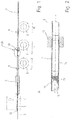
- FIG. 1 shows the device according to the invention in the form of a production line for drawing longitudinally welded pipes 1 in a continuous manufacturing process.
- the finished tube 1 is made of a strip material 2, which is formed in a tube forming station 3 to a tube 1.
- the opposite longitudinal edges of the strip material 2 are in the subsequent welding station 4 to a longitudinally welded pipe. 1 welded together.
- the heated by the welding process pipe 1 then enters a cooling station 5, which may be a water tank.
- the heated by welding tube 1 is cooled down before it is reduced in the drawing stages designated I to III by cold drawing to the desired final size.
- Each drawing stage I, II, III comprises a drawing drum 6, 7, 8, which allow the necessary tensile stresses to pull the tubing string through the pulling tool 9 and 10 located upstream of the drawing drum 6, 7, 8 respectively.
- the longitudinally welded pipe 1 is rounded.
- the tube 1 is thus pulled through a die 15.
- a lubricant lance 12 is provided for supplying lubricant 13 into the interior of the tube 1, which protrudes into the cooling station 5.
- the lubricant 13, as in FIG. 2 can be seen flowing in an area in the tube 1, in which it can not come to a smoke or inflammation of the lubricant 13.
- This is the case in particular in the rear half of the cooling station 5, since here the temperature of the tube inner side 16 has been cooled down to less than 100 ° C, so that the lubricant 13 immediately after insertion into the tube 1 through an end opening in the lubricant lance 12 is also kept below 100 ° C.
- the lubricant lance 12 even longer and to introduce the lubricant 13 behind the cooling station 5.
- the local temperature is decisive. It is possible within the scope of the invention to use interchangeable lubricant lances 12, depending on the pipe diameter and depending on the composition and viscosity of the lubricant 13, these introduce earlier in the cooling station 5 or rather towards the end of the cooling station 5 in the tube 1.
- FIG. 2 shows in enlarged scale the area A of FIG. 1 , ie the drawing stage II, in which an inner draw takes place by means of the inner mandrel 11.
- the inner mandrel 11 is a substantially cylindrical body whose ends are adapted to the internal geometry of a rotating die 15.
- the inner mandrel 11 is characterized by a relatively long cylindrical central part. The length of this central part is many times greater than the diameter of the pipe to be pulled 1. This forms a hydrodynamic lubricant film 14 between the inner mandrel 11 and the inner side 16 of the tube 1 from.
- this can be rotated by 180 °. He is trained symmetrically.
- a hydrodynamic lubricant film 14 is essential for reducing the coefficients of friction, so that the tube 1 can be deformed in the area of the die 15 at all.
- a corresponding lubricant reservoir 17 is formed in front of the inner mandrel 11.
- By forming lubricant film 14 is an inside smoothing of the weld of the longitudinally welded pipe 1. The wall thickness of the tube 1 is not reduced here.
- the die 15 As a further measure for reducing the frictional stresses is provided to rotate the die 15 at a relatively high speed.
- the die 15 preferably rotates at 1000 rpm or more.
Landscapes
- Engineering & Computer Science (AREA)
- Mechanical Engineering (AREA)
- Metal Extraction Processes (AREA)
Claims (8)
- Dispositif d'étirage de tubes (1) à soudure longitudinale avec un poste de formage de tube (3) et avec un poste de soudure (4), avec un poste de refroidissement (5) placé à la suite et avec ensuite plusieurs étages d'étirage (I, II, III) installés les uns derrière les autres, dans lequel l'outil d'étirage (10) d'au moins un étage d'étirage (II) comprend une matrice (15) et un mandrin intérieur flottant (11) qui est graissé avec l'apport d'un lubrifiant (13),
caractérisé en ce qu'une lance de lubrifiant (12) est prévue pour apporter le lubrifiant (13) dans le tube (1), laquelle lance s'étend à travers le poste de soudure (4) en direction du poste de refroidissement (5), la zone de l'apport de lubrifiant étant située dans ou derrière le poste de refroidissement (5),
dans lequela) soit le premier étage d'étirage (I) traversé est un poste d'étirage de corps creux pour réduire le diamètre de tube et l'autre étage d'étirage (II) suivant sert à lisser côté intérieur un joint de soudure du tube (1) sous l'influence du mandrin intérieur flottant (11) graissé avec le lubrifiant (13) sans que le mandrin intérieur (11) se trouve en contact métallique direct avec le tube (1),b) soit un poste de calibrage destiné à arrondir à l'intérieur le tube (1) est placé en amont d'un premier étage d'étirage (I) à traverser, le premier étage d'étirage (I) servant alors à lisser côté intérieur un joint de soudure du tube (1) sous l'influence du mandrin intérieur flottant (11) graissé avec le lubrifiant (13) sans que le mandrin intérieur (11) se trouve en contact métallique direct avec le tube (1) et un étage d'étirage (II, III) suivant étant un poste d'étirage de corps creux pour réduire le diamètre de tube. - Dispositif selon la revendication 1, caractérisé en ce que la lance de lubrifiant (12) s'étend jusque dans la moitié du poste de refroidissement (5) qui est éloignée du poste de soudure (4).
- Dispositif selon la revendication 1 ou 2, caractérisé en ce que des moyens destinés à un entraînement en rotation pendant l'opération d'étirage sont associés aux matrices (15) des outils d'étirage, la vitesse de rotation de la matrice (15) étant supérieure à 800 tours/minute.
- Dispositif selon la revendication 3, caractérisé en ce que la vitesse de rotation est supérieure à 1 000 tours/minute.
- Procédé d'étirage d'un tube (1) à soudure longitudinale au moyen d'un dispositif selon l'une des revendications 1 à 4,
dans lequel un matériau en bande (2) est formé en un tube (1) dans un poste de formage de tube (3), puis des arêtes longitudinales du matériau en bande transformé (2) qui se font face sont soudées ensemble dans un poste de soudure (4), puis le tube (1) traverse un poste de refroidissement (5) et ensuite plusieurs étages d'étirage (I, II, III) installés les uns derrière les autres à distance les uns des autres sont traversés, l'outil d'étirage (10) d'un étage d'étirage (II) comprenant une matrice (15) et un mandrin intérieur flottant (11) qui est graissé avec l'apport d'un lubrifiant (13),
caractérisé en ce qu'une lance de lubrifiant (12) est agencée dans le tube (1), laquelle lance sert à apporter le lubrifiant (13) dans le tube (1), le lubrifiant (13) étant apporté dans le tube (1) dans ou après le poste de refroidissement (5),
dans lequela) soit le tube (1) est étiré creux dans un premier étage d'étirage (I) et est lissé côté intérieur dans un autre étage d'étirage (II) sous l'influence du mandrin intérieur flottant (11) graissé avec le lubrifiant (13) sans que le mandrin intérieur (11) se trouve en contact métallique direct avec le tube (1),b) soit le tube (1) est lissé côté intérieur dans un premier étage d'étirage (I) sous l'influence du mandrin intérieur flottant (11) graissé avec le lubrifiant (13) sans que le mandrin intérieur (11) se trouve en contact métallique direct avec le tube (1), un poste de calibrage dans lequel le tube (1) est arrondi à l'intérieur étant placé en amont du premier étage d'étirage (I) et le tube (1) étant étiré creux dans au moins un autre étage d'étirage (II) placé en aval du premier étage d'étirage (I). - Procédé selon la revendication 5, caractérisé en ce que le lubrifiant (13) est introduit dans une zone dans laquelle la température du lubrifiant (13) immédiatement après l'introduction dans le tube (1) ne dépasse pas 100 °C.
- Procédé selon la revendication 5 ou 6, caractérisé en ce que la matrice (15) d'un outil d'étirage (9, 10) pendant l'opération d'étirage tourne avec une vitesse de rotation de plus de 800 tours/minute.
- Procédé selon la revendication 7, caractérisé en ce que la matrice (15) tourne avec une vitesse de rotation de plus de 1 000 tours/minute.
Applications Claiming Priority (1)
| Application Number | Priority Date | Filing Date | Title |
|---|---|---|---|
| DE201110052258 DE102011052258B4 (de) | 2011-07-28 | 2011-07-28 | Vorrichtung und Verfahren zum Ziehen von längsnahtgeschweißten Rohren |
Publications (2)
| Publication Number | Publication Date |
|---|---|
| EP2551027A1 EP2551027A1 (fr) | 2013-01-30 |
| EP2551027B1 true EP2551027B1 (fr) | 2017-06-21 |
Family
ID=46614301
Family Applications (1)
| Application Number | Title | Priority Date | Filing Date |
|---|---|---|---|
| EP12177475.6A Not-in-force EP2551027B1 (fr) | 2011-07-28 | 2012-07-23 | Dispositif et procédé destinés à l'étirage de tuyaux à soudure longitudinale |
Country Status (2)
| Country | Link |
|---|---|
| EP (1) | EP2551027B1 (fr) |
| DE (1) | DE102011052258B4 (fr) |
Family Cites Families (6)
| Publication number | Priority date | Publication date | Assignee | Title |
|---|---|---|---|---|
| DE2354161C3 (de) * | 1973-10-29 | 1979-10-25 | Schumag Gmbh, 5100 Aachen | Vorrichtung zur kontinuierlichen Herstellung von längsgeschweißten Rohren aus Metallband |
| DE2558671C2 (de) | 1975-12-24 | 1985-10-24 | Benteler-Werke Ag, 4794 Schloss Neuhaus | Kaltziehvorrichtung zum Reduzieren von Rohren |
| JPS5997724A (ja) * | 1982-11-26 | 1984-06-05 | Kobe Steel Ltd | 内面溝付管の製造方法及びその装置 |
| DE3542681A1 (de) * | 1985-12-03 | 1987-06-04 | Oppermann Willi Friedrich | Verfahren zur herstellung gezogener qualitaetsrohre |
| DE10151827A1 (de) * | 2001-10-20 | 2003-04-30 | Nexans | Verfahren zur kontinuierlichen Herstellung eines längsnahtgeschweissten Metallrohres |
| DE102004053021A1 (de) * | 2004-11-03 | 2006-05-04 | Nexans | Verfahren zur Ermittlung der Wanddicke eines Metallrohres |
-
2011
- 2011-07-28 DE DE201110052258 patent/DE102011052258B4/de not_active Expired - Fee Related
-
2012
- 2012-07-23 EP EP12177475.6A patent/EP2551027B1/fr not_active Not-in-force
Non-Patent Citations (1)
| Title |
|---|
| None * |
Also Published As
| Publication number | Publication date |
|---|---|
| DE102011052258B4 (de) | 2014-12-24 |
| DE102011052258A1 (de) | 2013-01-31 |
| EP2551027A1 (fr) | 2013-01-30 |
Similar Documents
| Publication | Publication Date | Title |
|---|---|---|
| EP3389887B1 (fr) | Procédé de fabrication d'un tube haute pression | |
| EP3049200B1 (fr) | Procédé de forgeage à chaud d'un corps creux sans soudure en matériau difficile à déformer | |
| EP2591866A1 (fr) | Procédé de fabrication d'une pièce creuse à rotation symétrique et pièce creuse fabriquée ensuite | |
| EP2127777A1 (fr) | Dispositif et procédé de fabrication ou de traitement de pièces à usiner à partir d'une ébauche, en particulier pour former des profils internes ou des dentures intérieures | |
| DE102013102704A1 (de) | Verfahren zum Herstellen eines Stahlrohres mit Reinigung der Rohrinnenwand | |
| DE102013102703A1 (de) | Verfahren zum Herstellen eines Stahlrohres mit Reinigung der Rohraußenwand | |
| DE2320545C3 (de) | Vorrichtung zur Stauchumformung langgestreckter metallischer Werkstücke | |
| DE2651812A1 (de) | Verfahren und vorrichtung zum kaltformen von langgestreckten stahlwerkstuecken | |
| DE102011052258B4 (de) | Vorrichtung und Verfahren zum Ziehen von längsnahtgeschweißten Rohren | |
| DE102008045279A1 (de) | Verfahren und Vorrichtung zur spanlosen Herstellung wenigstens eines verzahnten Bauteils | |
| DE2056473A1 (de) | Vorrichtung zur Herstellung von Strängen | |
| DE102010041164B4 (de) | Verfahren zum Herstellen eines Bohrers | |
| DE102016002542B3 (de) | Verfahren zur Herstellung von innenverzahnten Schiebemuffen | |
| EP3056786A1 (fr) | Dispositif de coupe destine a sectionner la paroi d'une conduite dans le sens de la longueur | |
| EP2991786B1 (fr) | Procédé de fabrication d'un corps façonné en fils métalliques à partir d'un tissu métallique, et corps façonné en fils métalliques correspondant | |
| DE640955C (de) | Verfahren zur Herstellung von nahtlosen Metallrohren | |
| DE102011052260A1 (de) | Vorrichtung und Verfahren zum Ziehen von längsnahtgeschweißten Rohren | |
| DE102008044870A1 (de) | Verfahren zur Herstellung eines Schwimmers, unter Verwendung eines Schaftes mit mindestens einem darauf angeordneten Kaliber (Schwimmer) sowie dergestalt hergestellter Schwimmer | |
| DE2354161C3 (de) | Vorrichtung zur kontinuierlichen Herstellung von längsgeschweißten Rohren aus Metallband | |
| DE102014014827A1 (de) | Kupplungshohlwelle eines Antriebs eines Schienenfahrzeuges und Verfahren zu ihrer Herstellung | |
| AT514503B1 (de) | Zahnstange kalt umgeformt mit Gewindenut | |
| DE102013105629A1 (de) | Ziehmaschine zum Umformen eines länglich ausgedehnten Werkstücks | |
| DE10040309C1 (de) | Herstellungsverfahren für einen Sinterstab und Sinterstab | |
| AT296118B (de) | Leichtmetallhülse mit schraubenförmigen Innenzügen, sowie Verfahren und Vorrichtung zur Herstellung derselben | |
| DE921867C (de) | Verfahren sowie Vorrichtung zur Herstellung von Rippenrohr und Rippenrohr |
Legal Events
| Date | Code | Title | Description |
|---|---|---|---|
| PUAI | Public reference made under article 153(3) epc to a published international application that has entered the european phase |
Free format text: ORIGINAL CODE: 0009012 |
|
| AK | Designated contracting states |
Kind code of ref document: A1 Designated state(s): AL AT BE BG CH CY CZ DE DK EE ES FI FR GB GR HR HU IE IS IT LI LT LU LV MC MK MT NL NO PL PT RO RS SE SI SK SM TR |
|
| AX | Request for extension of the european patent |
Extension state: BA ME |
|
| 17P | Request for examination filed |
Effective date: 20130722 |
|
| GRAP | Despatch of communication of intention to grant a patent |
Free format text: ORIGINAL CODE: EPIDOSNIGR1 |
|
| STAA | Information on the status of an ep patent application or granted ep patent |
Free format text: STATUS: GRANT OF PATENT IS INTENDED |
|
| INTG | Intention to grant announced |
Effective date: 20170301 |
|
| RAP1 | Party data changed (applicant data changed or rights of an application transferred) |
Owner name: BENTELER STEEL/TUBE GMBH |
|
| GRAS | Grant fee paid |
Free format text: ORIGINAL CODE: EPIDOSNIGR3 |
|
| GRAA | (expected) grant |
Free format text: ORIGINAL CODE: 0009210 |
|
| STAA | Information on the status of an ep patent application or granted ep patent |
Free format text: STATUS: THE PATENT HAS BEEN GRANTED |
|
| RBV | Designated contracting states (corrected) |
Designated state(s): AL AT BE BG CH CY CZ DK EE ES FI FR GB GR HR HU IE IS IT LI LT LU LV MC MK MT NL NO PL PT RO RS SE SI SK SM TR |
|
| REG | Reference to a national code |
Ref country code: DE Ref legal event code: R108 |
|
| AK | Designated contracting states |
Kind code of ref document: B1 Designated state(s): AL AT BE BG CH CY CZ DK EE ES FI FR GB GR HR HU IE IS IT LI LT LU LV MC MK MT NL NO PL PT RO RS SE SI SK SM TR |
|
| REG | Reference to a national code |
Ref country code: GB Ref legal event code: FG4D Free format text: NOT ENGLISH |
|
| REG | Reference to a national code |
Ref country code: CH Ref legal event code: EP |
|
| REG | Reference to a national code |
Ref country code: IE Ref legal event code: FG4D Free format text: LANGUAGE OF EP DOCUMENT: GERMAN |
|
| REG | Reference to a national code |
Ref country code: AT Ref legal event code: REF Ref document number: 902453 Country of ref document: AT Kind code of ref document: T Effective date: 20170715 |
|
| REG | Reference to a national code |
Ref country code: NL Ref legal event code: MP Effective date: 20170621 |
|
| PG25 | Lapsed in a contracting state [announced via postgrant information from national office to epo] |
Ref country code: HR Free format text: LAPSE BECAUSE OF FAILURE TO SUBMIT A TRANSLATION OF THE DESCRIPTION OR TO PAY THE FEE WITHIN THE PRESCRIBED TIME-LIMIT Effective date: 20170621 Ref country code: NO Free format text: LAPSE BECAUSE OF FAILURE TO SUBMIT A TRANSLATION OF THE DESCRIPTION OR TO PAY THE FEE WITHIN THE PRESCRIBED TIME-LIMIT Effective date: 20170921 Ref country code: FI Free format text: LAPSE BECAUSE OF FAILURE TO SUBMIT A TRANSLATION OF THE DESCRIPTION OR TO PAY THE FEE WITHIN THE PRESCRIBED TIME-LIMIT Effective date: 20170621 Ref country code: LT Free format text: LAPSE BECAUSE OF FAILURE TO SUBMIT A TRANSLATION OF THE DESCRIPTION OR TO PAY THE FEE WITHIN THE PRESCRIBED TIME-LIMIT Effective date: 20170621 Ref country code: GR Free format text: LAPSE BECAUSE OF FAILURE TO SUBMIT A TRANSLATION OF THE DESCRIPTION OR TO PAY THE FEE WITHIN THE PRESCRIBED TIME-LIMIT Effective date: 20170922 |
|
| REG | Reference to a national code |
Ref country code: LT Ref legal event code: MG4D |
|
| PG25 | Lapsed in a contracting state [announced via postgrant information from national office to epo] |
Ref country code: SE Free format text: LAPSE BECAUSE OF FAILURE TO SUBMIT A TRANSLATION OF THE DESCRIPTION OR TO PAY THE FEE WITHIN THE PRESCRIBED TIME-LIMIT Effective date: 20170621 Ref country code: RS Free format text: LAPSE BECAUSE OF FAILURE TO SUBMIT A TRANSLATION OF THE DESCRIPTION OR TO PAY THE FEE WITHIN THE PRESCRIBED TIME-LIMIT Effective date: 20170621 Ref country code: LV Free format text: LAPSE BECAUSE OF FAILURE TO SUBMIT A TRANSLATION OF THE DESCRIPTION OR TO PAY THE FEE WITHIN THE PRESCRIBED TIME-LIMIT Effective date: 20170621 Ref country code: BG Free format text: LAPSE BECAUSE OF FAILURE TO SUBMIT A TRANSLATION OF THE DESCRIPTION OR TO PAY THE FEE WITHIN THE PRESCRIBED TIME-LIMIT Effective date: 20170921 Ref country code: NL Free format text: LAPSE BECAUSE OF FAILURE TO SUBMIT A TRANSLATION OF THE DESCRIPTION OR TO PAY THE FEE WITHIN THE PRESCRIBED TIME-LIMIT Effective date: 20170621 |
|
| PG25 | Lapsed in a contracting state [announced via postgrant information from national office to epo] |
Ref country code: SK Free format text: LAPSE BECAUSE OF FAILURE TO SUBMIT A TRANSLATION OF THE DESCRIPTION OR TO PAY THE FEE WITHIN THE PRESCRIBED TIME-LIMIT Effective date: 20170621 Ref country code: CZ Free format text: LAPSE BECAUSE OF FAILURE TO SUBMIT A TRANSLATION OF THE DESCRIPTION OR TO PAY THE FEE WITHIN THE PRESCRIBED TIME-LIMIT Effective date: 20170621 Ref country code: EE Free format text: LAPSE BECAUSE OF FAILURE TO SUBMIT A TRANSLATION OF THE DESCRIPTION OR TO PAY THE FEE WITHIN THE PRESCRIBED TIME-LIMIT Effective date: 20170621 Ref country code: RO Free format text: LAPSE BECAUSE OF FAILURE TO SUBMIT A TRANSLATION OF THE DESCRIPTION OR TO PAY THE FEE WITHIN THE PRESCRIBED TIME-LIMIT Effective date: 20170621 |
|
| PG25 | Lapsed in a contracting state [announced via postgrant information from national office to epo] |
Ref country code: ES Free format text: LAPSE BECAUSE OF FAILURE TO SUBMIT A TRANSLATION OF THE DESCRIPTION OR TO PAY THE FEE WITHIN THE PRESCRIBED TIME-LIMIT Effective date: 20170621 Ref country code: PL Free format text: LAPSE BECAUSE OF FAILURE TO SUBMIT A TRANSLATION OF THE DESCRIPTION OR TO PAY THE FEE WITHIN THE PRESCRIBED TIME-LIMIT Effective date: 20170621 Ref country code: IS Free format text: LAPSE BECAUSE OF FAILURE TO SUBMIT A TRANSLATION OF THE DESCRIPTION OR TO PAY THE FEE WITHIN THE PRESCRIBED TIME-LIMIT Effective date: 20171021 Ref country code: SM Free format text: LAPSE BECAUSE OF FAILURE TO SUBMIT A TRANSLATION OF THE DESCRIPTION OR TO PAY THE FEE WITHIN THE PRESCRIBED TIME-LIMIT Effective date: 20170621 |
|
| PG25 | Lapsed in a contracting state [announced via postgrant information from national office to epo] |
Ref country code: MC Free format text: LAPSE BECAUSE OF FAILURE TO SUBMIT A TRANSLATION OF THE DESCRIPTION OR TO PAY THE FEE WITHIN THE PRESCRIBED TIME-LIMIT Effective date: 20170621 |
|
| REG | Reference to a national code |
Ref country code: IE Ref legal event code: MM4A |
|
| PLBE | No opposition filed within time limit |
Free format text: ORIGINAL CODE: 0009261 |
|
| REG | Reference to a national code |
Ref country code: FR Ref legal event code: ST Effective date: 20180330 |
|
| STAA | Information on the status of an ep patent application or granted ep patent |
Free format text: STATUS: NO OPPOSITION FILED WITHIN TIME LIMIT |
|
| PG25 | Lapsed in a contracting state [announced via postgrant information from national office to epo] |
Ref country code: DK Free format text: LAPSE BECAUSE OF FAILURE TO SUBMIT A TRANSLATION OF THE DESCRIPTION OR TO PAY THE FEE WITHIN THE PRESCRIBED TIME-LIMIT Effective date: 20170621 Ref country code: IE Free format text: LAPSE BECAUSE OF NON-PAYMENT OF DUE FEES Effective date: 20170723 |
|
| GBPC | Gb: european patent ceased through non-payment of renewal fee |
Effective date: 20170921 |
|
| 26N | No opposition filed |
Effective date: 20180322 |
|
| PG25 | Lapsed in a contracting state [announced via postgrant information from national office to epo] |
Ref country code: FR Free format text: LAPSE BECAUSE OF NON-PAYMENT OF DUE FEES Effective date: 20170821 |
|
| REG | Reference to a national code |
Ref country code: BE Ref legal event code: MM Effective date: 20170731 |
|
| PG25 | Lapsed in a contracting state [announced via postgrant information from national office to epo] |
Ref country code: LU Free format text: LAPSE BECAUSE OF NON-PAYMENT OF DUE FEES Effective date: 20170723 |
|
| PG25 | Lapsed in a contracting state [announced via postgrant information from national office to epo] |
Ref country code: GB Free format text: LAPSE BECAUSE OF NON-PAYMENT OF DUE FEES Effective date: 20170921 |
|
| PG25 | Lapsed in a contracting state [announced via postgrant information from national office to epo] |
Ref country code: BE Free format text: LAPSE BECAUSE OF NON-PAYMENT OF DUE FEES Effective date: 20170731 Ref country code: SI Free format text: LAPSE BECAUSE OF FAILURE TO SUBMIT A TRANSLATION OF THE DESCRIPTION OR TO PAY THE FEE WITHIN THE PRESCRIBED TIME-LIMIT Effective date: 20170621 |
|
| REG | Reference to a national code |
Ref country code: AT Ref legal event code: MM01 Ref document number: 902453 Country of ref document: AT Kind code of ref document: T Effective date: 20170723 |
|
| PG25 | Lapsed in a contracting state [announced via postgrant information from national office to epo] |
Ref country code: MT Free format text: LAPSE BECAUSE OF FAILURE TO SUBMIT A TRANSLATION OF THE DESCRIPTION OR TO PAY THE FEE WITHIN THE PRESCRIBED TIME-LIMIT Effective date: 20170621 |
|
| PG25 | Lapsed in a contracting state [announced via postgrant information from national office to epo] |
Ref country code: AT Free format text: LAPSE BECAUSE OF NON-PAYMENT OF DUE FEES Effective date: 20170723 |
|
| PG25 | Lapsed in a contracting state [announced via postgrant information from national office to epo] |
Ref country code: HU Free format text: LAPSE BECAUSE OF FAILURE TO SUBMIT A TRANSLATION OF THE DESCRIPTION OR TO PAY THE FEE WITHIN THE PRESCRIBED TIME-LIMIT; INVALID AB INITIO Effective date: 20120723 |
|
| PG25 | Lapsed in a contracting state [announced via postgrant information from national office to epo] |
Ref country code: CY Free format text: LAPSE BECAUSE OF NON-PAYMENT OF DUE FEES Effective date: 20170621 |
|
| PG25 | Lapsed in a contracting state [announced via postgrant information from national office to epo] |
Ref country code: MK Free format text: LAPSE BECAUSE OF FAILURE TO SUBMIT A TRANSLATION OF THE DESCRIPTION OR TO PAY THE FEE WITHIN THE PRESCRIBED TIME-LIMIT Effective date: 20170621 |
|
| PG25 | Lapsed in a contracting state [announced via postgrant information from national office to epo] |
Ref country code: TR Free format text: LAPSE BECAUSE OF FAILURE TO SUBMIT A TRANSLATION OF THE DESCRIPTION OR TO PAY THE FEE WITHIN THE PRESCRIBED TIME-LIMIT Effective date: 20170621 |
|
| PG25 | Lapsed in a contracting state [announced via postgrant information from national office to epo] |
Ref country code: PT Free format text: LAPSE BECAUSE OF FAILURE TO SUBMIT A TRANSLATION OF THE DESCRIPTION OR TO PAY THE FEE WITHIN THE PRESCRIBED TIME-LIMIT Effective date: 20170621 |
|
| PG25 | Lapsed in a contracting state [announced via postgrant information from national office to epo] |
Ref country code: AL Free format text: LAPSE BECAUSE OF FAILURE TO SUBMIT A TRANSLATION OF THE DESCRIPTION OR TO PAY THE FEE WITHIN THE PRESCRIBED TIME-LIMIT Effective date: 20170621 |
|
| PGFP | Annual fee paid to national office [announced via postgrant information from national office to epo] |
Ref country code: IT Payment date: 20210727 Year of fee payment: 10 |
|
| PGFP | Annual fee paid to national office [announced via postgrant information from national office to epo] |
Ref country code: CH Payment date: 20210721 Year of fee payment: 10 |
|
| REG | Reference to a national code |
Ref country code: CH Ref legal event code: PL |
|
| PG25 | Lapsed in a contracting state [announced via postgrant information from national office to epo] |
Ref country code: LI Free format text: LAPSE BECAUSE OF NON-PAYMENT OF DUE FEES Effective date: 20220731 Ref country code: CH Free format text: LAPSE BECAUSE OF NON-PAYMENT OF DUE FEES Effective date: 20220731 |
|
| PG25 | Lapsed in a contracting state [announced via postgrant information from national office to epo] |
Ref country code: IT Free format text: LAPSE BECAUSE OF NON-PAYMENT OF DUE FEES Effective date: 20220723 |