EP2551045A2 - Géométrie d'un canal de refroidissement - Google Patents
Géométrie d'un canal de refroidissement Download PDFInfo
- Publication number
- EP2551045A2 EP2551045A2 EP12187853A EP12187853A EP2551045A2 EP 2551045 A2 EP2551045 A2 EP 2551045A2 EP 12187853 A EP12187853 A EP 12187853A EP 12187853 A EP12187853 A EP 12187853A EP 2551045 A2 EP2551045 A2 EP 2551045A2
- Authority
- EP
- European Patent Office
- Prior art keywords
- cooling channel
- drill
- cross
- cutting tool
- wmax
- Prior art date
- Legal status (The legal status is an assumption and is not a legal conclusion. Google has not performed a legal analysis and makes no representation as to the accuracy of the status listed.)
- Withdrawn
Links
Images






Classifications
-
- B—PERFORMING OPERATIONS; TRANSPORTING
- B23—MACHINE TOOLS; METAL-WORKING NOT OTHERWISE PROVIDED FOR
- B23B—TURNING; BORING
- B23B51/00—Tools for drilling machines
- B23B51/06—Drills with lubricating or cooling equipment
-
- B—PERFORMING OPERATIONS; TRANSPORTING
- B23—MACHINE TOOLS; METAL-WORKING NOT OTHERWISE PROVIDED FOR
- B23B—TURNING; BORING
- B23B51/00—Tools for drilling machines
-
- B—PERFORMING OPERATIONS; TRANSPORTING
- B23—MACHINE TOOLS; METAL-WORKING NOT OTHERWISE PROVIDED FOR
- B23B—TURNING; BORING
- B23B51/00—Tools for drilling machines
- B23B51/02—Twist drills
-
- B—PERFORMING OPERATIONS; TRANSPORTING
- B23—MACHINE TOOLS; METAL-WORKING NOT OTHERWISE PROVIDED FOR
- B23Q—DETAILS, COMPONENTS, OR ACCESSORIES FOR MACHINE TOOLS, e.g. ARRANGEMENTS FOR COPYING OR CONTROLLING; MACHINE TOOLS IN GENERAL CHARACTERISED BY THE CONSTRUCTION OF PARTICULAR DETAILS OR COMPONENTS; COMBINATIONS OR ASSOCIATIONS OF METAL-WORKING MACHINES, NOT DIRECTED TO A PARTICULAR RESULT
- B23Q11/00—Accessories fitted to machine tools for keeping tools or parts of the machine in good working condition or for cooling work; Safety devices specially combined with or arranged in, or specially adapted for use in connection with, machine tools
- B23Q11/10—Arrangements for cooling or lubricating tools or work
Definitions
- the invention relates to a rotary-driven cutting or inserting tool, in particular a drill, according to the preamble of claim 1.
- cutting tools For coolant or lubricant supply, cutting tools have internal cooling channels through which the coolant is led to the drill tip. In addition to the function of cooling or lubricating the drill tip, the coolant also has the function of improving chip removal.
- the coolant In order to transport the chips out of the chip flute, in particular during deep hole drilling, the coolant has to be supplied partly under high pressure, whereby the internal cooling channel or the drill has to endure corresponding pressures non-destructively.
- efforts are being made to design the cooling ducts as large as possible.
- With increasing length and decreasing diameter of the drilling tool it is becoming increasingly difficult to dimension the internal cooling channels so that a corresponding coolant throughput or coolant pressure is provided without the stability of the drill suffers.
- the size of the cooling channels is limited by the distance to the drill back or chip space. Too thin webs cause cracks and tool breaks.
- the cooling channels In the case of multi-blade insert tools, the cooling channels must also have a certain minimum distance from each other, since otherwise impairments of the drill bit geometry, i. e.g. the chisel edge or a Ausspitzung be caused.
- the object of the invention is to improve an internally cooled cutting tool of the generic type with respect to coolant throughput, breakage, compression torsional and bending strength.
- the invention is based on the finding that the stresses occurring at the cooling channel resulting from the shape of the cooling channel and thus mainly from the notch effect of the cooling channel at its smallest radii in the load direction. Furthermore, it has been recognized that the resistance that an insert tool, such as a drill bit or mill, can counteract this spike, i. for its stability and ultimately whether it comes to cracking or premature breakage of the tool, in addition to the voltage peaks occurring at the cooling channel, the distance of the cooling channels to the chip space and thus the position of the cooling channel on the web is crucial.
- Minimum radii in the range of 0.35 to 0.9 times, in particular 0.5 to 0.85 times, preferably 0.6 to 0.85 times, particularly preferably 0.7 to 0.8 times ,
- the throughput quantities increase almost proportionally with respect to an insert tool with a round cooling channel geometry, wherein the increase in notch stresses with increasing cross-sectional area in the region of the inventive cooling channel geometry is surprisingly small in comparison to that in conventional trigon profiles.
- the cooling channel profile according to the invention can thus be realized cross-sectional areas that would lead to a failure of the tool with a round profile with the same coolant throughput due to low wall clearances.
- the minimum wall thickness is limited only by the desired flow rate upwards.
- cooling channel geometry according to the invention is particularly suitable for smaller tools, where it is particularly important to optimize space utilization with regard to strength and coolant flow on the tool web. This knowledge was taken into account by the upper limits according to the invention for the minimum wall thicknesses, which increase more strongly above a certain nominal diameter than in the area of smaller diameter values.
- the sintered blanks are usually designed as cylindrical rods with already formed cooling channels. That is, for example, from a blank having a raw diameter of 6.2 mm, tools having nominal diameters of 4 mm, 5 mm and 6 mm are manufactured. For the 6mm tool with the same cooling channeling as the 4mm tool, the minimum wall thickness between the cooling channel and the outer circumference of the tool would therefore be 1 mm larger.
- the minimum wall thicknesses between the cooling channel and the outer circumference of the drill bit, or rake surface or chip clearance can, of course, be chosen differently. From a strength point of view, it is particularly important to the minimum distance or the minimum wall thickness between the cooling channel and rake face, which can thus be selected to be greater than the minimum wall thickness between the cooling channel and SpanokION. Even with respect to the minimum wall thickness between the cooling channel and the outer circumference of the drill bit, the minimum wall thickness between the cooling channel and the clamping surface can be provided with larger values in order to take account of the higher strength requirement.
- a minimum wall thickness between the cooling channel and the outer circumference of the drill can be greater than that between the cooling channel and the rake face.
- the proposed cross-sectional geometry is equally suitable for drills, reamers and cutters, for example, end mills. It should be mentioned that the cooling channel geometry according to the invention can also be used advantageously in step tools, for example stepped drills. In this case, therefore, the specified nominal diameter refers to the tool diameter at the tool tip or to the diameter of the pilot hole.
- Drills with the cooling channel profile according to the invention can endure high load values non-destructively over a long service life, both in the load case of compressive forces and torques which are typical during drilling, and in transverse or bending moment load, as they occur when entering the workpiece to be machined , Similar transverse force and bending stresses also occur with constant or reverse cutters.
- the achieved coolant throughput in terms of quantity and pressure drop over the tool length high demands.
- the effect of increasing the coolant throughput with a reduced pressure drop is that due to the large radii, a favorable hydraulic radius, i. a relation to the enveloping lateral surface of the cooling channel results in large cross-sectional area of the cooling channel.
- the average flow velocity which depends essentially on the pipe frictional force and the counterforce caused by the pressure drop, is thus higher than the conventional trine profiles, so that a higher throughput is achieved with the same cross-sectional area.
- the cooling channel geometry according to the invention is particularly suitable for tools in which the conflict between sufficient coolant supply on the one hand and sufficient strength on the other hand is particularly problematic, usually for tools with small diameters and / or large tool length.
- the nominal diameter is in the range of 1 mm to 25 mm, in particular 1 mm to 16 mm.
- the advantages of the inventive cooling channel geometry are particularly great in the case of even smaller tools whose nominal diameters are in a range from 1 mm to 12 mm, in particular in a range from 1 mm to 6 mm.
- the cross-sectional geometry of the invention may be sinful to accomplish maximum coolant delivery, particularly in deep hole drilling where the coolant is forced into the internal cooling channels at up to 1000 bar to provide sufficient pressure to remove the chips from the wellbore squeeze.
- the cross-sectional geometry according to the invention can be used, for example, in single-lip drills. However, it has a particularly advantageous effect in the case of tools with two or more cutting edges since, with small web widths, a correspondingly smaller installation space for the internal cooling channels is also available there.
- the cooling channel geometry according to the invention is furthermore suitable both for straight as well as coiled or spiral tools.
- the two curvature maxima of the cooling channel cross section lie on the same radial coordinate which is greater than or equal to the radial coordinate of the circle enclosed by the cooling channel cross section.
- the applied radius at the two curvature maxima is the same; according to claim 6, the cooling channel cross-section is symmetrical to a radially extending axis to the drill axis.
- the cooling channel has the shape of an ellipse in cross-section according to claim 7.
- Preferred values for the The ratio of the ellipse main axis / minor axis are 1.18 to 1.65, particularly preferably 1.25 to 1.43, for example 1.43.
- an ellipse with a large cooling channel cross-section may still be milled.
- an end mill having the smallest radius of the ellipse an ellipse-like bore in the tool bridge is created by moving - starting from the smallest radius - at the maximum curvature with diameter expansion to the largest radius at the minimum curvature.
- the radii do not change steadily, but only in the area of the transition from the largest radius to the smallest radius, while the smallest radius is maintained over a non-zero length at the maximum of curvature.
- the plasticized mass in an extrusion head first flows essentially freely into a nozzle mouthpiece, in order to be pressed along the longitudinal axis of at least one pin secured to the nozzle mandrel to the outlet opening of the nozzle and through it.
- the nozzle has a circular-cylindrical, preferably substantially smooth surface, so that the resulting blank has a fully cylindrical outer contour.
- the streamed Pin is held against rotation on the nozzle mandrel.
- the flow in the nozzle tip is thereby induced on the one hand by the pitch of the helices of the pin and on the other hand by a rotating portion of the nozzle orifice a radial component.
- a plastic deformation of the extruded mass or an irregular structure formation or density distribution in the mass can be avoided, since the radial component of the flow is not forced by Verdrall Nuren or deflecting devices such as vanes, etc., but is achieved solely by the rotational movement of the rotatable portion of the nozzle orifice.
- the radial movement of the flow is thus not caused by deflection of an obstacle standing in the way of the flow, but solely on the friction forces inherent in the extruded mass, which cause the mass to be taken by the rotational movement of the nozzle portion, wherein the thus induced rotational movement of the Starting nozzle wall independently propagates towards the interior of the nozzle until a stationary helical flow sets, in a dependent of the shear stress and thus the viscosity and toughness of the extruded mass ratio.
- the cooling channel can be dimensioned with a smaller minimum wall thickness between cooling channel and main cutting edge due to the low notch stresses at the bend maximum than in designs in which the curvature maxima are radially further outward because there are narrower radii than in the elliptical design.
- the radially inner side of the cooling channel contour has rectilinear leg sections on which the wires can be securely supported in the drawing mold during helixing.
- the tool can be equipped with conventional coatings, at least in the area of the sharp cutting edges. If it is a hard material layer, this is preferably made thin, wherein the thickness of the layer is preferably in the range between 0.5 and 3 microns.
- the hard material layer consists for example of diamond, preferably monocrystalline diamond. However, it can also be embodied as a titanium-nitride or as a titanium-aluminum-nitride layer, since such layers are deposited sufficiently thin. But also other hard material layers, for example TiC, Ti (C, N), ceramics, eg Al 2 O 3 , NbC, HfN, Ti (C, O, N), multi-layer coatings of TiC / Ti (C, N) / TiN, multilayer coatings Ceramic coatings, in particular with intermediate layers of TiN or Ti (C, N), etc. are conceivable.
- This soft coating preferably consists of MoS 2 .
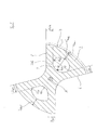
- Fig. 1 is a cross-sectional view of a double-edged, drill with two webs 2 and two flutes 1 can be seen.
- the webs are each bounded by a rake face 5, at the non-cutting side by a chip removal surface 6.
- the outer periphery of the drill is assigned the reference numeral 7.
- the webs are approximately symmetrical to a web center line S, which is located radially to the drill axis A.
- the center M of a circle K which is located entirely within the cross-sectional area of the local cooling channel bore 3.
- the center M "of the local circle K with the same diameter 2R 0 is located somewhat away from the rake face and completely offset within the cross-sectional area of the local cooling-chamber bore 3.
- a plurality of the respective cooling channel surrounding cooling channel contours 30, 31, 32 are compared according to different embodiments of the invention: At the lower web an elliptical contour 30 for the cooling channel 3 is shown by a solid line, another contour 31 for the cooling channel 3 with a dashed line. At the upper web a contour 32 for the cooling channel 3 is shown in dashed line.
- the cooling channel contours 30, 31 in this case have a symmetrical to the symmetry shape, while the cooling channel 32 deviates only on the non-cutting side of the predetermined by the touching enclosed circle K contour.
- the curvature radii R 1 , R 1 'and R 1 " are in each case at the curvature maxima, wherein the contours 30, 31 each have two equally curved curvature maxima, while at the contour 32 only a maximum curvature radius R 1 " is present.
- the passage surface extraction is limited only by the minimum wall thicknesses to be complied with, for the sake of clarity, only for the Breaking strength of the drill particularly important minimum wall thickness D SPE , d SPA and d SPA "between the cooling channel 3 and clamping surface 5 for each of the cooling channel contours 30, 31, 32 is located.
- the minimum wall thicknesses are in turn given by the minimum strength that the drill should achieve, and thus also by the radii R 1 , or R 1 'or R 1 "at the maximum curvature of the respective cooling channel contour 30, 31, 32. This is reflected therein again in that for the elliptical cooling channel contour 30, a smaller minimum wall thickness D SPE than for the cooling channel contours 31, 32 can be used with curvature maxima offset outwards (minimum wall thickness d SPA ).
- the cooling channel contours 30, 31 maintain the minimum wall thickness D SPE or d SPA between the cooling channel 3 and the rake face 5, which essentially corresponds to the (unnamed) minimum wall thickness between the cooling channel 3 and the chip flank 6.
- the contour 32 has, for example, a greater minimum wall thickness d SPA "on the side facing the rake surface 5 than on the side facing away from the rake surface 5.
- the center M 'of the enclosed circle is offset away from the cutting side, and on the other hand the cooling channel contour 32 only on the chip flank 6 side facing a maximum curvature (radius R 1 ") on.
- the course of the cooling channel contour 32 also makes it clear that, within the scope of the invention, cooling channel cross sections are also conceivable in which the maximum curvature lies on the side facing the rake face.
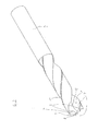
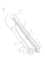
- Fig. 2 shows an isometric view of a coiled drilling tool with an elliptical cooling channel cross-sectional contour 30.
- the tool has at its by the flutes 1 separated from each other two webs 2 each have a main cutting edge 4.
- the flutes 1 and webs 2 are wound at a spiral angle of about 30 ° to a running as a solid cylinder drill shank 9, to which the tool is clamped in a tool holder or in a chuck.
- the internal cooling channels 3 extend through the entire tool and are twisted at the same spiral angle as flutes 1 and webs 2.
- solid carbide boring tools which have high compressive strength, torsional rigidity, hardness and wear resistance.
- Such high-performance tools are also able to cope with the high loads that occur, for example, in hard machining, dry machining, reduced-quantity lubrication MQL and high-speed machining HSC.
- MQL capability and significantly higher cutting performance are not in opposite directions, but can be realized simultaneously.
- Drilling tools that have been developed for use with MQL for example, run at much higher feed rates than tools for conventional cooling lubrication. In this case, the amount of coolant supplied to a crucial role.
- HPC high-performance cutting
- the feed rate is not only limited by the speed, but on the one hand also by the fact that it must be ensured that no chaff accumulation during chip removal.
- straight grooved tools - in this regard is on the Figs. 4 . 6 . 8th and 10 directed - has that in Fig. 2 illustrated coiled tool thereby decisive advantages. Because the coiled design allows easier removal of the mixture of chips and lubricant.
- the coolant is introduced to a large extent directly into the flute, since the exit surface of the cooling channels 3 extends over both sections of the divided by a so-called four-surface bevel ground plane 13, so that a large part of the coolant directly into the flute flows.
- the flute such that it widens from the drill tip to the drill shank.
- centering coiled tools are advantageous because these tools can be supported over its entire outer circumference in the hole. This in Fig. 2 For this purpose, the tool shown has a support phase 11 starting at the cutting corner.
- cooling channel geometry was found by various experiments. In each case, a number except the Cooling channel geometry uniform tools subjected to the same nominal diameter of existing pressure and torsion existing load and the voltage peaks occurring at the notch bases, ie determined the maximum curvature of the cooling channel cross-sectional contours.
- the drill with a circular cooling channel profile is the Fig. 1 (Cooling channel contour follows everywhere the enclosed circle with radius R 0 ).
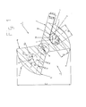
- Four drills with inventive cooling channel contour are in the FIGS. 3 to 10 shown on an enlarged scale.
- Each of the illustrated cooling channel profiles 30E ( Fig. 3 . 4 ), 30I ( Fig. 5 . 6 ) 30II ( Fig. 7 . 8th ) and 30III ( Fig. 9 . 10 ) includes the circle with radius R 0 touching. In this case, the same features with the same reference numerals as in Fig. 1 named.
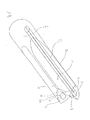
- FIGS. 4 . 6 . 8th and 10 In each case, a drill according to an embodiment of the invention is shown in an isometric view.
- the drills each have straight flutes 1 and webs 2 with guide chamfers 11, 12 on the side of the main cutting edge 4 and on the side facing away from the main cutting edge 4.
- the cooling channels 3 occur at the unspecified open space of the drill, which is bounded on the back by a 10 Ausspitzung for Querniciverkürzung.
- the Figs. 3 . 5 . 7 and 9 show a drill cross section of the in the Figs. 4 . 6 . 8th and 10 shown drill, wherein an inventively designed cooling channel on the lower drill bit for comparison purposes on the upper drill bit each a cooling channel was compared with conventional Trigonprofil.
- a drill with conventional cooling channel trigon profile with the same inscribed circle with radius R 0 is in Fig. 11 shown in isometric view.
- Such a designed cooling channel profile is in each case contrasted with a cooling channel profile designed according to the invention.
- d SPX , d SFX and D AUX the minimum wall thicknesses between cooling channel 3 and rake face 5, cooling channel 3 and chip flank 6 and between cooling channel 3 and outer circumference 7 are denoted respectively, with R 1X and R 2X respectively the smallest and the largest to the cooling channel contour adjacent radius, where X is E, I, II, III.
- the corresponding sizes in the trigonal Kühkanalprofil were designated D SPT , D SFT and D AUT .
- Fig. 12 Values according to the invention for the lower limit W min of the minimum wall thicknesses over the diameter D are plotted.
- the tools according to the invention in this case have minimum wall thicknesses d AUX, d SPX, d SFX on the left or on the left of the graph W min, 1 , in particular left of the graph W min, 2 , preferably left of the graph W min, 3 , for example left of W min, 4 lie.
- cooling channel contours would be conceivable in which the radii at the maximum of curvature on the side of the cooling channel facing the rake face are larger than on the side facing the chip rake face.
- the invention is not limited to coiled or grooved single- or multi-bladed tools with any tip geometry and groove-land ratio in which the cutting directly on the tool head, but can also for tools with screwed or soldered indexable or indexable inserts and at Tools with soldered on the shaft cutting part or drill head are used.
Landscapes
- Engineering & Computer Science (AREA)
- Mechanical Engineering (AREA)
- Drilling Tools (AREA)
Applications Claiming Priority (3)
| Application Number | Priority Date | Filing Date | Title |
|---|---|---|---|
| DE20219761 | 2002-12-19 | ||
| DE20219824U DE20219824U1 (de) | 2002-12-19 | 2002-12-20 | Drehangetriebenes Zerspanungswerkzeug |
| EP03799451.4A EP1572405B1 (fr) | 2002-12-19 | 2003-12-18 | Geometrie de canal de refroidissement |
Related Parent Applications (2)
| Application Number | Title | Priority Date | Filing Date |
|---|---|---|---|
| EP03799451.4 Division | 2003-12-18 | ||
| EP03799451.4A Division-Into EP1572405B1 (fr) | 2002-12-19 | 2003-12-18 | Geometrie de canal de refroidissement |
Publications (1)
| Publication Number | Publication Date |
|---|---|
| EP2551045A2 true EP2551045A2 (fr) | 2013-01-30 |
Family
ID=32240647
Family Applications (1)
| Application Number | Title | Priority Date | Filing Date |
|---|---|---|---|
| EP12187853A Withdrawn EP2551045A2 (fr) | 2002-12-19 | 2003-12-18 | Géométrie d'un canal de refroidissement |
Country Status (5)
| Country | Link |
|---|---|
| EP (1) | EP2551045A2 (fr) |
| JP (2) | JP4885453B2 (fr) |
| KR (1) | KR101197544B1 (fr) |
| DE (2) | DE20219824U1 (fr) |
| ES (1) | ES2481166T3 (fr) |
Cited By (3)
| Publication number | Priority date | Publication date | Assignee | Title |
|---|---|---|---|---|
| CN108580982A (zh) * | 2018-06-28 | 2018-09-28 | 苏州大学 | 一种微织构内冷麻花钻及其制造方法 |
| CN112404526A (zh) * | 2019-08-21 | 2021-02-26 | 肯纳金属公司 | 具有增强的流体递送的旋转式切削工具 |
| CN114603479A (zh) * | 2022-03-24 | 2022-06-10 | 北京理工大学 | 一种含有内部冷却通道的微磨棒 |
Families Citing this family (12)
| Publication number | Priority date | Publication date | Assignee | Title |
|---|---|---|---|---|
| JP2008137125A (ja) * | 2006-12-04 | 2008-06-19 | Mitsubishi Materials Corp | ドリル |
| JP5447129B2 (ja) * | 2009-06-15 | 2014-03-19 | 三菱マテリアル株式会社 | クーラント穴付きドリル |
| JP6108264B2 (ja) * | 2012-10-30 | 2017-04-05 | 住友電工ハードメタル株式会社 | 2枚刃ダブルマージンドリル |
| WO2014118881A1 (fr) * | 2013-01-29 | 2014-08-07 | オーエスジー株式会社 | Foret |
| DE102013205056A1 (de) * | 2013-03-21 | 2014-09-25 | Gühring KG | Mehrschneidiges Bohrwerkzeug mit innenliegenden Kühlkanälen |
| EP2979794A4 (fr) * | 2013-03-26 | 2016-11-16 | Osg Corp | Foret à trois arêtes avec trou d'alimentation en fluide de coupe |
| DE112017003782T5 (de) * | 2016-07-26 | 2019-04-11 | Kyocera Corporation | Schneidwerkzeug und Verfahren des Herstellens eines maschinell-bearbeiteten Produkts |
| US12303986B2 (en) | 2018-12-26 | 2025-05-20 | Mitsubishi Materials Corporation | Rotating tool with coolant hole |
| JP7463689B2 (ja) * | 2018-12-26 | 2024-04-09 | 三菱マテリアル株式会社 | クーラント穴付き回転工具 |
| US10814406B1 (en) * | 2019-04-24 | 2020-10-27 | Raytheon Technologies Corporation | Internal cooling passages for rotating cutting tools |
| KR102887562B1 (ko) * | 2021-05-10 | 2025-11-18 | 오에스지 가부시키가이샤 | 드릴 |
| JP7544300B1 (ja) | 2024-02-06 | 2024-09-03 | 株式会社タンガロイ | ボディ及び切削工具 |
Citations (4)
| Publication number | Priority date | Publication date | Assignee | Title |
|---|---|---|---|---|
| US2422994A (en) | 1944-01-03 | 1947-06-24 | Carboloy Company Inc | Twist drill |
| DE3629035A1 (de) | 1986-08-27 | 1988-03-10 | Stellram Gmbh | Einteiliges spanabhebendes werkzeug |
| DE4242336A1 (de) | 1992-12-15 | 1994-06-16 | Guehring Joerg Dr | Verfahren und Vorrichtung zur kontinuierlichen Herstellung von zylindrischen Stäben mit zumindest einem innenliegenden, wendelförmigen Kanal, und nach diesem Verfahren hergestellter Sinterrohling |
| DE19942966A1 (de) | 1999-09-09 | 2001-03-22 | Arno Friedrichs | Verfahren und Vorrichtung zur Herstellung eines Sintermetall-Rohlings mit innenliegenden, wendelförmigen Ausnehmungen |
Family Cites Families (4)
| Publication number | Priority date | Publication date | Assignee | Title |
|---|---|---|---|---|
| JPS5796722U (fr) * | 1980-12-05 | 1982-06-14 | ||
| JPS63216611A (ja) * | 1987-03-04 | 1988-09-08 | Mitsubishi Metal Corp | ドリル |
| JPS6442816U (fr) * | 1987-09-09 | 1989-03-14 | ||
| JPH11197926A (ja) * | 1998-01-12 | 1999-07-27 | Mitsubishi Materials Corp | 油穴付きドリル |
-
2002
- 2002-12-20 DE DE20219824U patent/DE20219824U1/de not_active Expired - Lifetime
-
2003
- 2003-12-18 ES ES03799451.4T patent/ES2481166T3/es not_active Expired - Lifetime
- 2003-12-18 DE DE20321908U patent/DE20321908U1/de not_active Expired - Lifetime
- 2003-12-18 EP EP12187853A patent/EP2551045A2/fr not_active Withdrawn
- 2003-12-18 JP JP2004561065A patent/JP4885453B2/ja not_active Expired - Fee Related
- 2003-12-18 KR KR1020117017491A patent/KR101197544B1/ko not_active Expired - Fee Related
-
2011
- 2011-02-04 JP JP2011023007A patent/JP5539913B2/ja not_active Expired - Lifetime
Patent Citations (4)
| Publication number | Priority date | Publication date | Assignee | Title |
|---|---|---|---|---|
| US2422994A (en) | 1944-01-03 | 1947-06-24 | Carboloy Company Inc | Twist drill |
| DE3629035A1 (de) | 1986-08-27 | 1988-03-10 | Stellram Gmbh | Einteiliges spanabhebendes werkzeug |
| DE4242336A1 (de) | 1992-12-15 | 1994-06-16 | Guehring Joerg Dr | Verfahren und Vorrichtung zur kontinuierlichen Herstellung von zylindrischen Stäben mit zumindest einem innenliegenden, wendelförmigen Kanal, und nach diesem Verfahren hergestellter Sinterrohling |
| DE19942966A1 (de) | 1999-09-09 | 2001-03-22 | Arno Friedrichs | Verfahren und Vorrichtung zur Herstellung eines Sintermetall-Rohlings mit innenliegenden, wendelförmigen Ausnehmungen |
Cited By (4)
| Publication number | Priority date | Publication date | Assignee | Title |
|---|---|---|---|---|
| CN108580982A (zh) * | 2018-06-28 | 2018-09-28 | 苏州大学 | 一种微织构内冷麻花钻及其制造方法 |
| CN112404526A (zh) * | 2019-08-21 | 2021-02-26 | 肯纳金属公司 | 具有增强的流体递送的旋转式切削工具 |
| US12208455B2 (en) | 2019-08-21 | 2025-01-28 | Kennametal Inc. | Rotary cutting tool with enhanced coolant delivery |
| CN114603479A (zh) * | 2022-03-24 | 2022-06-10 | 北京理工大学 | 一种含有内部冷却通道的微磨棒 |
Also Published As
| Publication number | Publication date |
|---|---|
| JP5539913B2 (ja) | 2014-07-02 |
| KR101197544B1 (ko) | 2012-11-09 |
| JP2006510494A (ja) | 2006-03-30 |
| DE20219824U1 (de) | 2004-04-29 |
| JP2011121173A (ja) | 2011-06-23 |
| DE20321908U1 (de) | 2013-05-15 |
| ES2481166T3 (es) | 2014-07-29 |
| KR20110094148A (ko) | 2011-08-19 |
| JP4885453B2 (ja) | 2012-02-29 |
Similar Documents
| Publication | Publication Date | Title |
|---|---|---|
| EP1572405B1 (fr) | Geometrie de canal de refroidissement | |
| EP1572402B1 (fr) | Canaux de refroidissement helicoidaux | |
| EP1864737B1 (fr) | Outil d'usinage par enlevement de copeaux | |
| EP1334787B1 (fr) | Outil de coupe rotatif | |
| EP2146816B1 (fr) | Outil d'enlèvement de copeaux pouvant être entraîné en rotation | |
| EP3285948B1 (fr) | Outil rotatif à conduit d'agent de refroidissement conique et conduits de sortie d'agent de refroidissement disposés de façon décalée et procédé de fabrication de ceux-ci | |
| EP0118035B1 (fr) | Outil de forage et procédé pour sa fabrication | |
| EP0883455B1 (fr) | Outil d'alesage pour machines-outils et son procede de production | |
| DE112011102902B4 (de) | Scheibe für einen Schneideinsatz und Schneideinsatz-Scheiben-Anordnung mit interner Kühlmittelabgabe | |
| EP2148757B1 (fr) | Outil d'enlèvement de copeaux et procede d'alimentation des arêtes de coupe d'un tel outil avec fluide frigorigène /lubrifiant | |
| DE10331328B4 (de) | Tieflochbohrer mit nach hinten schräg verlaufendem Rücken und Verfahren zum Bohren eines Loches | |
| EP2830799B1 (fr) | Foret de perçage | |
| EP2323792B1 (fr) | Outil de perçage à arêtes coupantes multiples | |
| EP2551045A2 (fr) | Géométrie d'un canal de refroidissement | |
| EP2076345B1 (fr) | Outil de perçage modulaire et son procédé de fabrication | |
| EP0712343A1 (fr) | Foret helico dal | |
| EP3791982A1 (fr) | Outil de fraisage avec de canaux de refroidissement | |
| EP1407848B1 (fr) | Outil de filetage avec refroidissement | |
| DE102016221363A1 (de) | Bohrwerkzeug und Verfahren zum Herstellen von Bohrungen | |
| EP2448704B1 (fr) | Foret pour forage profond | |
| EP1610919B2 (fr) | Foret a une levre et son procede de production | |
| WO2010034410A1 (fr) | Outil d'usinage par enlèvement de copeaux | |
| DE20219753U1 (de) | Tieflochbohrer | |
| DE10144241A1 (de) | Bohrer | |
| DE19735024B4 (de) | Bohrer für zusätzliche Rückseitenbearbeitung |
Legal Events
| Date | Code | Title | Description |
|---|---|---|---|
| PUAI | Public reference made under article 153(3) epc to a published international application that has entered the european phase |
Free format text: ORIGINAL CODE: 0009012 |
|
| AC | Divisional application: reference to earlier application |
Ref document number: 1572405 Country of ref document: EP Kind code of ref document: P |
|
| AK | Designated contracting states |
Kind code of ref document: A2 Designated state(s): AT BE BG CH CY CZ DE DK EE ES FI FR GB GR HU IE IT LI LU MC NL PT RO SE SI SK TR |
|
| STAA | Information on the status of an ep patent application or granted ep patent |
Free format text: STATUS: THE APPLICATION IS DEEMED TO BE WITHDRAWN |
|
| 18D | Application deemed to be withdrawn |
Effective date: 20130702 |