EP2551131B1 - Dispositif pour verrouiller des jantes de roues pour des véhicules sur un support des machines de service de pneus - Google Patents
Dispositif pour verrouiller des jantes de roues pour des véhicules sur un support des machines de service de pneus Download PDFInfo
- Publication number
- EP2551131B1 EP2551131B1 EP12176999.6A EP12176999A EP2551131B1 EP 2551131 B1 EP2551131 B1 EP 2551131B1 EP 12176999 A EP12176999 A EP 12176999A EP 2551131 B1 EP2551131 B1 EP 2551131B1
- Authority
- EP
- European Patent Office
- Prior art keywords
- rim
- fact
- locking
- stop element
- elastic band
- Prior art date
- Legal status (The legal status is an assumption and is not a legal conclusion. Google has not performed a legal analysis and makes no representation as to the accuracy of the status listed.)
- Active
Links
Images


Classifications
-
- B—PERFORMING OPERATIONS; TRANSPORTING
- B60—VEHICLES IN GENERAL
- B60C—VEHICLE TYRES; TYRE INFLATION; TYRE CHANGING; CONNECTING VALVES TO INFLATABLE ELASTIC BODIES IN GENERAL; DEVICES OR ARRANGEMENTS RELATED TO TYRES
- B60C25/00—Apparatus or tools adapted for mounting, removing or inspecting tyres
- B60C25/01—Apparatus or tools adapted for mounting, removing or inspecting tyres for removing tyres from or mounting tyres on wheels
- B60C25/05—Machines
- B60C25/132—Machines for removing and mounting tyres
- B60C25/135—Machines for removing and mounting tyres having a tyre support or a tool, movable along wheel axis
- B60C25/138—Machines for removing and mounting tyres having a tyre support or a tool, movable along wheel axis with rotary motion of tool or tyre support
-
- B—PERFORMING OPERATIONS; TRANSPORTING
- B60—VEHICLES IN GENERAL
- B60B—VEHICLE WHEELS; CASTORS; AXLES FOR WHEELS OR CASTORS; INCREASING WHEEL ADHESION
- B60B30/00—Means for holding wheels or parts thereof
- B60B30/06—Means for holding wheels or parts thereof engaging the wheel body, e.g. the rim
-
- B—PERFORMING OPERATIONS; TRANSPORTING
- B60—VEHICLES IN GENERAL
- B60C—VEHICLE TYRES; TYRE INFLATION; TYRE CHANGING; CONNECTING VALVES TO INFLATABLE ELASTIC BODIES IN GENERAL; DEVICES OR ARRANGEMENTS RELATED TO TYRES
- B60C25/00—Apparatus or tools adapted for mounting, removing or inspecting tyres
- B60C25/01—Apparatus or tools adapted for mounting, removing or inspecting tyres for removing tyres from or mounting tyres on wheels
- B60C25/05—Machines
- B60C25/053—Support of wheel parts during machine operation
- B60C25/0542—Support of wheel parts during machine operation with self-centering means, e.g. cones
-
- G—PHYSICS
- G01—MEASURING; TESTING
- G01M—TESTING STATIC OR DYNAMIC BALANCE OF MACHINES OR STRUCTURES; TESTING OF STRUCTURES OR APPARATUS, NOT OTHERWISE PROVIDED FOR
- G01M1/00—Testing static or dynamic balance of machines or structures
- G01M1/02—Details of balancing machines or devices
- G01M1/04—Adaptation of bearing support assemblies for receiving the body to be tested
- G01M1/045—Adaptation of bearing support assemblies for receiving the body to be tested the body being a vehicle wheel
Definitions
- the present invention relates to a device for locking wheel rims for vehicles on repair workshop machines, particularly tyre-changing machines or the like.
- tyre-changing machines which allow fitting and removing tyres onto and off the relative rim of a vehicle wheel, e.g., for carrying out maintenance jobs or replacing the rim and/or the tyre itself.
- Such tyre-changing machines generally consist of a base structure supporting gripping and rotating means for gripping and rotating the rim of a wheel, having a device for locking the rim, and of at least a tool bearing arm having one or more tools suitable for removing and/or fitting the tyre from and onto the rim.
- gripping and rotating means for gripping and rotating the rim exist, having different devices for locking the rim.
- a first type consists of a fastening plate for the rim, which is fitted on the base structure of the tyre-changing machine in a rotatable way around a central work axis and which has four rim gripping clamps.
- the clamps are moving from the centre towards the outside of the plate and vice versa, between a closing configuration, corresponding to the positioning of the clamps at the centre of the plate, and an opening configuration, corresponding to the positioning of the clamps at the edge of the plate.
- clamps are subject to breakage and also the actuators for moving the clamps themselves are subject to faults.
- a second type of gripping and rotating means comprises a resting plate for the rim, which is fitted on the base structure of the tyre-changing machine in a way rotatable around a central work axis, by means of the operation of suitable motor means.
- the resting plate has a threaded hole inside which a rim locking pin can be fitted and screwed.
- the locking pin has a thread along its entire length or a part of it and has, in particular, an extremal portion that can be fitted and screwed inside the hole on the resting plate, through the central through hole on the rim, and a grip opposite such extremal portion.
- a locking cone To the pin is coupled, axially rotatable, a locking cone, generally having suitable grip knobs, suitable for engaging on the rim in correspondence to the central through hole for the locking of the rim itself on the resting plate.
- the rim is positioned on the resting plate, with the central hole of the rim aligned with the threaded hole on the plate.
- the above extremal portion of the pin is screwed inside the hole on the plate, until the cone is positioned in contact or in any way in the proximity of the rim, above this.
- the screwing up of the cone on the pin obtained by means of the knobs, allows positioning the cone itself in contact with the rim, inside the through hole, and therefore allows locking the rim on the resting plate.
- This type of chuck does however have a number of drawbacks.
- a further type of gripping and rotating means comprising a support fitted to the base of the machine that extends substantially vertically and has a resting plate of the rim rotating by means of the operation of motor means.
- the resting plate has a hole for the introduction of the extremal section of a locking element of the rim.
- the locking element is made up of a pin with an extremity having a grip and the opposite extremity with at least a first fastening element which is associable in a removable way with a corresponding second fastening element inside the channel which can be accessed to through the hole on the plate.
- the pin can be associated e.g. in a removable way inside the channel by means of a so-called bayonet coupling or the like.
- the pin can have at least a first shoulder which can be coupled to one or more corresponding second shoulders made on several points on the inner surface of the channel.
- a locking cone To the pin is coupled axially rotating a locking cone, generally having suitable grip knobs, suitable for engaging on the rim in correspondence to the central through hole for locking the rim itself on the resting plate.
- the rim is positioned on the resting plate, with the rim central hole aligned with the hole on the plate.
- the pin is fitted in the hole on the resting plate and the first shoulder on the extremal portion of the pin is coupled to one of the second shoulders inside the channel, so as to position the cone as close as possible to the rim, above this.
- the screwing up of the cone on the pin made by turning the knobs, allows to position the cone itself in contact with the rim, inside the through hole and allows, therefore, the locking of the rim on the resting plate.
- the locking of the rim on the resting plate requires, first of all, the correct coupling between the extremity of the pin and one of the corresponding fastening elements in the channel, so as to position the cone as close as possible to the rim; then, the operator must screw up the cone until the complete locking of the rim.
- the locking of the rim therefore, implies the execution of two distinct operations by the operator which prove to be long in terms of time.
- the coupling operation between the extremity of the pin and one of the corresponding fastening elements in the channel is not always immediate and it is not always easy for the operator to perform such operation so as to move the locking cone as close as possible to the rim.
- the document DE 298 09 051 U1 describes a device for locking rims of vehicle wheels on tire removal machines, comprising attachment means removably associable to the support means of the rim of a wheel, and a stop element engageable on a circle placed on support means for the locking of the rim itself.
- the document DE 3641295 A1 describes a balancing machine for vehicle wheels, in which the wheels are blocked on a head-balancing through a special cover locking.
- the document EP 2 218 591 A1 describes a device for locking a rim, provided with a rod engageable within a central hole of a rotary support of a tire changing machine, of a slider sliding on the rod and activation means to move the cursor along the rod.
- the main aim of the present invention is to provide a device for locking wheel rims for vehicles on repair workshop machines, particularly tyre-changing machines or the like, that allows to make the locking operation of the rim easier.
- Another object of the present invention is to provide a device for locking wheel rims for vehicles on repair workshop machines, particularly tyre-changing machines or the like, that allows to overcome the mentioned drawbacks of the state of the art in the ambit of a simple, rational, easy and effective to use as well as low cost solution.
- the present device for locking wheel rims for vehicles on repair workshop machines, particularly tyre-changing machines or the like comprising fastening means associable in a removable way with supporting means of the rim of a wheel in a vehicle repair workshop machine or the like and at least a stop element engageable on a rim arranged on said supporting means for locking the rim itself, characterised by the fact that it comprises simultaneous movement means associated with said fastening means and with said stop element and suitable for simultaneously moving said fastening means and said stop element between a release configuration, wherein said fastening means are released from said supporting means and said stop element is substantially disengaged from said rim, and a locking configuration, wherein said fastening means are associated with said supporting means and said stop element is engaged on said rim.
- the device 1 can be used to lock the rim of a wheel A on supporting means B of a conventional tyre-changing machine C.
- the supporting means B in particular, can be made of means for gripping and rotating the rim of a wheel A conventionally used on a tyre-changing machine C, having a plate D which is suitable for accommodating the rim in support and which is suitable for being placed in rotation by suitable motor means of the tyre-changing machine C.
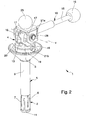
- the device 1 comprises fastening means 2 associable in a removable way with the supporting means B and a stop element 3 engageable on the rim, in turn arranged on the supporting means B, for locking the rim itself.
- the device 1 comprises simultaneous movement means, indicated altogether in the illustrations by the reference 4, associated with the fastening means 2 and with the stop element 3.
- the simultaneous movement means 4 are suitable for simultaneously moving both the fastening means 2 and the stop element 3 between a release configuration, wherein the fastening means 2 are released from the supporting means B and the stop element 3 is substantially disengaged from the rim, and the locking configuration, wherein the fastening means 2 are anchored to the supporting means B and the stop element 3 is engaged on the rim.
- the device 1 comprises an extremal section 5 of elongated shape which can be fitted with play in a corresponding housing E on the supporting means B of the rim, through a specific hole made on the plate D.
- the fastening means 2 are made in correspondence to the free extremity of the extremal section 5, so as to allow the locking of the extremal section itself inside the housing E on the supporting means B.
- the fastening means 2 comprise an expansion clamp element 6 made along a portion of the extremal section 5 and suitable for being expanded to engage on the inner surface of the housing E in the above locking configuration.
- the expansion clamp element 6 can consist of an elastic band which, in the specific embodiment shown in the illustrations, is made by means of a spring made up of a closed metal band having cross cuts 7.
- the elastic band 6 presses on the inner surface of the housing E, blocking the extremal section 5 inside the housing itself and, therefore, anchoring the entire device 1 to the supporting means B.
- the extremal section 5 has a substantially tubular and elongated shape.
- the extremal section 5 comprises a tubular element 9 and an elastic band 6 arranged in correspondence to the free extremity of the extremal section 5 and coaxially with respect to the tubular element 9.
- the stop element 3 has a substantially truncated-cone shape and is intended to engage on the rim arranged on the supporting means B, in correspondence to the central hole of the rim itself.
- tubular element 9 is fitted in a through hole made on the stop element 3 and extends from the portion of the stop element 3 meant to engage on the edge of the central hole of the rim.
- the simultaneous movement means 4 comprise a control device indicated altogether in the illustrations by the reference 10, associated with the fastening means 2 and the stop element 3.
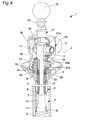
- control device 10 can be positioned between an idle position, shown in figure 3 , wherein the fastening means 2 and the stop element 3 are in the release configuration, and a working position, shown in figure 4 , wherein the fastening means 2 and the stop element 3 are in locking configuration.
- the simultaneous movement means 4 comprise expansion means 11 associated with the elastic band 6 and suitable for expanding and reducing such elastic band 6 to move it from the release configuration to the locking configuration and vice versa.
- the expansion means 11 are made up of a truncated-cone element fitted axially sliding inside the elastic band 6 and engaged sliding on the inner surface of the elastic band itself.
- the truncated-cone element 11 moves between an idle position, shown in figure 3 , wherein the elastic band 6 is in the release configuration, and a working position, shown in figure 4 , wherein the elastic band 6 is in the locking configuration.
- the elastic band 6 has a sloped inner surface 12 on which the outer surface of the truncated-cone element 11 engages sliding.
- the axial movement of the truncated-cone element 11 allows varying the diameter of the elastic band 6 in a uniform way, along the entire length of the elastic band itself.
- the simultaneous movement means 4 comprise a connection element 14 of elongated shape which connects the control device 10 to the expansion means 11.
- connection element 14 is made up of a rod fitted axially sliding inside the extremal section 5.
- the rod 14 has an extremity associated with the control device 10 and an opposite extremity provided with the truncated-cone element 11.
- the rod 14 is fitted axially sliding inside the tubular element 9 and is provided with the truncated-cone element 11 in correspondence to the elastic band 6.
- the rod 14 is axially sliding inside the extremal section 5 by means of the operation of the control device 10 between an extracted position, shown in figure 3 , wherein the control device 10 and the truncated-cone element 11 are in their respective idle positions, and a retracted position, shown in figure 4 , wherein the control device 10 and the truncated-cone element 11 are in the respective working positions.
- control device 10 is composed of an eccentric lever device or similar device.
- control device 10 Different types and shapes of the control device 10 cannot however be ruled out.
- control device 10 comprises a lever 15 having, at one extremity a grip 16 and, at the opposite extremity, a pair of cams 17.
- the lever 15 is made up of a telescopic arm which can be extended to facilitate locking/release operations, while the grip 16 at the free extremity of the lever 15 is made up of a knob.
- the cams 17 are associated with the stop element 3 and are rotatable by means of the rotation of the lever 15 between an idle position, shown in figure 3 , and the working position, shown in figure 4 , to move the stop element 3 between the release configuration and the locking configuration respectively.
- each of the cams 17 is housed revolving inside respective connecting rods 18.
- Each of the connecting rods 18, in turn, is hinged to a pusher element 19 of cylindrical shape arranged in contact with the stop element 3.
- the pusher element 19 is in part housed to measure in a respective recess obtained on the portion of the stop element 3 opposite the portion suitable for being moved into contact with the rim.
- the device 1 has elastic means 8 placed between the stop element 3 and the fastening means 2 suitable for being compressed during the movement of the stop element 3 from the release configuration to the locking configuration and suitable for releasing the elastic energy accumulated during the return of the pusher element 19 from the locking configuration to the release configuration.
- elastic means 8 are suitable for permitting a relative axial movement between the stop element 3 and the fastening means 2.
- the pusher element 19 has a transit hole for the rod 14.
- the pusher element 19 has a protrusion 22 suitable for engaging on a locator 24 on the outer surface of the tubular element 9 during movement from the locking configuration to the release configuration. This way, during such movement, the pusher element 19 drags the tubular element 9 upwards and this, in turn, drags the elastic band 6 upwards, forcing the movement of the elastic band itself from the locking configuration to the release configuration.
- the protrusion 22 is fitted inside a specific annular groove 23 obtained on the outer surface of the tubular element 9.
- the elastic means 8 are composed of a seal arranged around the tubular element 9 and housed inside the groove 23.
- the protrusion 22 is suitable for compressing the seal 8 during the movement of the pusher element 19 from the release configuration to the locking configuration.
- the pusher element 19 is composed of a first disc 19a and of a second disc 19b.
- the second disc 19b is fastened integral to the first disc 19a by means of threaded means 13 of the type of one or more screws.
- the second disc 19b is coupled with the tubular element 9 by means of the protrusion 22 and is positioned in contact with the stop element 3.
- each of the cams 17 is associated rotatable with the rod 14, around a rotation axis X substantially at right angles with the longitudinal axis of the rod itself, and is revolving by means of the rotation of the lever 15 between the idle position, shown in figure 3 , and the working position, shown in figure 4 , to move the rod 14 between the extracted position and the retracted position respectively.
- the extremity of the rod 14 opposite the extremity provided with the truncated-cone element 11 is fitted and fixed inside a bush 20.
- the cams 17 are associated rotatable with a first pin 21 a fitted in the bush 20 along the rotation axis X at right angles with respect to the longitudinal axis of the rod 14.
- the device 1 comprises an additional grip knob 25 fastened to a bracket 26 supporting the lever 15.
- the device 1 is initially in the configuration shown in the figure 3 , with the fastening means 2 and the stop element 3 in the release configuration.
- the operator inserts the extremal section 5 inside the respective housing E on the supporting means B, through the central hole on the rim.
- the device according to the invention allows locking the rim on a workshop machine by means of a single operation, making such locking operation much simpler and quicker to perform compared to devices of known type.
Landscapes
- Engineering & Computer Science (AREA)
- Mechanical Engineering (AREA)
- Physics & Mathematics (AREA)
- General Physics & Mathematics (AREA)
- Clamps And Clips (AREA)
- Tires In General (AREA)
- Lock And Its Accessories (AREA)
- Vehicle Cleaning, Maintenance, Repair, Refitting, And Outriggers (AREA)
Claims (13)
- Dispositif (1) de verrouillage de jantes de roues pour des véhicules sur des machines d'atelier de réparation, en particulier des machines de changement de pneu ou similaires, comprenant des moyens de fixation (2) pouvant être associés de manière démontable à des moyens de support (B) de la jante d'une roue (A) dans une machine d'atelier de réparation de véhicule, au moins un élément de butée (3) pouvant venir en engagement sur une jante disposée sur lesdits moyens de support (B) afin de verrouiller la jante elle-même, et au moins un tronçon terminal (5) de forme essentiellement allongée qui peut être ajusté dans un boîtier correspondant (E) sur lesdits moyens de support (B) de la jante, caractérisé par le fait qu'il comprend des moyens de déplacement simultané (4) associés auxdits moyens de fixation (2) et audit élément de butée (3) et aptes à déplacer simultanément lesdits moyens de fixation (2) et ledit élément de butée (3) entre une configuration de libération, dans laquelle lesdits moyens de fixation (2) sont libérés par rapport auxdits moyens de support (B) et ledit élément de butée (3) est essentiellement désengagé de ladite jante, et une configuration de verrouillage, dans laquelle lesdits moyens de fixation (2) sont associés auxdits moyens de support (B) et ledit élément de butée (3) est engagé sur ladite jante, et par le fait que lesdits moyens de fixation (2) comprennent au moins un élément de serrage à déploiement (6) constitué le long d'au moins une partie dudit tronçon terminal (5) et apte à être déployé pour venir en engagement sur la surface intérieure dudit boîtier (E) dans ladite configuration de verrouillage.
- Dispositif (1) selon la revendication 1, caractérisé par le fait que ledit élément de serrage à déploiement (6) comprend au moins une bande élastique (6) ou similaire.
- Dispositif (1) selon une ou plusieurs des revendications précédentes, caractérisé par le fait que ledit élément de butée (3) est essentiellement en forme de tronc de cône et est destiné à venir en engagement sur ladite jante, en correspondance avec l'orifice central traversant de ladite jante.
- Dispositif (1) selon une ou plusieurs des revendications précédentes, caractérisé par le fait que lesdits moyens de déplacement simultané (4) comprennent au moins un dispositif de commande (10) associé auxdits moyens de fixation (2) et audit élément de butée (3) et qui peut être placé entre une position de repos, dans laquelle lesdits moyens de fixation (2) et ledit élément de butée (3) sont dans ladite configuration de libération, et une configuration de fonctionnement, dans laquelle lesdits moyens de fixation (2) et ledit élément de butée (3) sont dans ladite configuration de verrouillage.
- Dispositif (1) selon une ou plusieurs des revendications précédentes, caractérisé par le fait que lesdits moyens de déplacement simultané (4) comprennent des moyens de déploiement (11) associés audit élément de serrage à déploiement (6) et aptes à déployer et à réduire ledit élément de serrage à déploiement (6) afin de le déplacer entre ladite configuration de libération et ladite configuration de verrouillage.
- Dispositif (1) selon la revendication 5, caractérisé par le fait que ledit élément de serrage à déploiement (6) comprend au moins une bande élastique (6) ou similaire, et que lesdits moyens de déploiement (11) comprennent au moins un élément en tronc de cône (11) ajusté en coulissant axialement à l'intérieur de ladite bande élastique (6), en étant engagé de manière coulissante sur au moins une partie de la surface intérieure de ladite bande élastique (6) et en étant mobile entre une position de repos, dans laquelle ladite bande élastique (6) est dans ladite configuration de libération, et une position de fonctionnement, dans laquelle ladite bande élastique (6) est dans ladite configuration de verrouillage.
- Dispositif (1) selon la revendication 6, caractérisé par le fait que ladite bande élastique (6) comporte une surface intérieure inclinée (12) sur laquelle la surface extérieure dudit élément en tronc de cône (11) est engagée en coulissant.
- Dispositif (1) selon une ou plusieurs des revendications précédentes, caractérisé par le fait que lesdits moyens de déplacement simultané (4) comprennent au moins un élément de liaison (14) entre ledit dispositif de commande (10) et lesdits moyens de déploiement (11).
- Dispositif (1) selon une ou plusieurs des revendications précédentes, caractérisé par le fait que ledit tronçon terminal (5) a une forme essentiellement tubulaire et allongée et comprend ladite bande élastique (6) le long d'au moins l'une de ses parties.
- Dispositif (1) selon une ou plusieurs des revendications précédentes, caractérisé par le fait que ledit élément de liaison (14) a une forme essentiellement allongée, est ajusté en coulissant axialement à l'intérieur dudit tronçon terminal (5), comporte une extrémité associée audit dispositif de commande (10) et une extrémité opposée associée auxdits moyens de déploiement (11), ledit élément de liaison (14) coulissant de manière axiale par mise en oeuvre fonctionnelle dudit dispositif de commande (10) et par rapport audit tronçon terminal (5) entre une position d'extraction, dans laquelle ledit dispositif de commande (10) et ledit élément en tronc de cône (11) sont dans les positions de repos respectives, et une position rétractée, dans laquelle ledit dispositif de commande (10) et ledit élément en tronc de cône (11) sont dans les positions de fonctionnement respectives.
- Dispositif (1) selon une ou plusieurs des revendications précédentes, caractérisé par le fait que ledit dispositif de commande (10) comprend au moins un dispositif de levier excentré ou similaire.
- Dispositif (1) selon une ou plusieurs des revendications précédentes, caractérisé par le fait que ledit dispositif de commande (10) comprend au moins un levier (15) et au moins une came (17) ou similaire associée, en ne formant qu'une pièce avec lui, audit levier (15).
- Dispositif (1) selon une ou plusieurs des revendications précédentes, caractérisé par le fait que ladite came (17) est associée de manière opérationnelle à au moins un élément de poussée (19) dudit élément de butée (3) et est associée audit élément de liaison (14) en étant de révolution autour d'un axe de rotation qui est sensiblement transversal à l'axe longitudinal dudit élément de liaison (14), ladite came (17) étant de révolution au moyen de la rotation dudit levier (15) entre ladite position de repos et ladite position de fonctionnement afin de déplacer ledit élément de butée (3) entre ladite configuration de libération et ladite configuration de verrouillage et afin de déplacer ledit élément de liaison (14) entre ladite position d'extraction et ladite position rétractée.
Applications Claiming Priority (1)
| Application Number | Priority Date | Filing Date | Title |
|---|---|---|---|
| IT000185A ITMO20110185A1 (it) | 2011-07-26 | 2011-07-26 | Dispositivo per il bloccaggio di cerchi di ruote per veicoli su macchine da autofficina, particolarmente macchine smontagomme o simili |
Publications (2)
| Publication Number | Publication Date |
|---|---|
| EP2551131A1 EP2551131A1 (fr) | 2013-01-30 |
| EP2551131B1 true EP2551131B1 (fr) | 2015-04-01 |
Family
ID=44584396
Family Applications (1)
| Application Number | Title | Priority Date | Filing Date |
|---|---|---|---|
| EP12176999.6A Active EP2551131B1 (fr) | 2011-07-26 | 2012-07-19 | Dispositif pour verrouiller des jantes de roues pour des véhicules sur un support des machines de service de pneus |
Country Status (6)
| Country | Link |
|---|---|
| US (1) | US9132706B2 (fr) |
| EP (1) | EP2551131B1 (fr) |
| JP (1) | JP6108198B2 (fr) |
| CN (1) | CN102896988B (fr) |
| ES (1) | ES2539682T3 (fr) |
| IT (1) | ITMO20110185A1 (fr) |
Families Citing this family (9)
| Publication number | Priority date | Publication date | Assignee | Title |
|---|---|---|---|---|
| ES2620974T3 (es) * | 2015-03-12 | 2017-06-30 | Corghi S.P.A. | Máquina de servicio de ruedas y método para bloquear una rueda a una unidad de soporte de ruedas |
| US10458875B2 (en) | 2015-04-22 | 2019-10-29 | Snap-On Equipment Srl A Unico Socio | Holding device for a rim of a vehicle wheel |
| EP3086104B1 (fr) * | 2015-04-22 | 2020-10-28 | Snap-on Equipment Srl a unico socio | Dispositif de fixation d'une jante de roue de véhicule |
| IT201600121351A1 (it) * | 2016-12-02 | 2018-06-02 | Snap On Equipment S R L A Unico Socio | Dispositivo e metodo di serraggio ruota per una macchina per la manutenzione delle ruote di veicoli a motore |
| DE102017114018B4 (de) * | 2017-06-23 | 2021-01-07 | Snap-On Equipment Srl A Unico Socio | Radservicemaschine mit Krafterfassungseinrichtung |
| CN110203013B (zh) * | 2019-06-27 | 2023-11-24 | 中信戴卡股份有限公司 | 一种车轮高精度组装装置 |
| IT201900011181A1 (it) | 2019-07-08 | 2021-01-08 | Beissbarth Gmbh | Dispositivo di bloccaggio per ruote in macchine da autofficina o simili |
| IT201900019864A1 (it) * | 2019-10-28 | 2021-04-28 | Beissbarth Gmbh | Macchina smontagomme |
| CN114179572B (zh) * | 2021-12-27 | 2022-08-23 | 伺轮智能机器人(南京)有限公司 | 用于锁定轮辋或车轮的锁紧头和快速锁紧装置 |
Family Cites Families (9)
| Publication number | Priority date | Publication date | Assignee | Title |
|---|---|---|---|---|
| FR2210244A5 (fr) * | 1972-12-12 | 1974-07-05 | Dunlop Ltd | |
| HU177080B (en) * | 1978-04-24 | 1981-07-28 | Hiradastechnikai Gepgyar | Workpiece clamping fixture |
| US4529024A (en) * | 1983-12-29 | 1985-07-16 | Fmc Corporation | Tire changer accessory for use with custom alloy rims |
| DE3641295A1 (de) * | 1986-12-03 | 1988-06-09 | Daimler Benz Ag | Wuchtmaschine fuer fahrzeugraeder |
| DE4200380C2 (de) * | 1992-01-09 | 1996-09-19 | Hofmann Werkstatt Technik | Verfahren und Vorrichtung zum Spannen und Lösen eines Rotors, insbesondere eines Kraftfahrzeugrades, an einer von einem Motor angetriebenen Hauptwelle einer Unwuchtmeßanordnung, insbesondere einer Radauswuchtmaschine |
| DE29809051U1 (de) * | 1998-05-19 | 1998-10-01 | Maul, Torsten, 08523 Plauen | Vorrichtung zum Spannen von Felgen und Rädern für Fahrzeuge |
| IT1319467B1 (it) * | 2000-05-22 | 2003-10-10 | Corghi Spa | Dispositivo di bloccaggio del cerchione per macchine smontagomme |
| ITVR20050059A1 (it) * | 2005-05-16 | 2006-11-17 | Butler Eng & Marketing | Gruppo di supporto e rotazione di un cerchione in particolare per una macchina monta-smontagomme. |
| ITRE20090009A1 (it) * | 2009-02-06 | 2010-08-07 | Corghi Spa | '' dispositivo per il bloccaggio di un cerchione '' |
-
2011
- 2011-07-26 IT IT000185A patent/ITMO20110185A1/it unknown
-
2012
- 2012-07-06 JP JP2012152593A patent/JP6108198B2/ja active Active
- 2012-07-17 US US13/551,082 patent/US9132706B2/en active Active
- 2012-07-18 CN CN201210249801.2A patent/CN102896988B/zh active Active
- 2012-07-19 ES ES12176999.6T patent/ES2539682T3/es active Active
- 2012-07-19 EP EP12176999.6A patent/EP2551131B1/fr active Active
Also Published As
| Publication number | Publication date |
|---|---|
| ITMO20110185A1 (it) | 2013-01-27 |
| US9132706B2 (en) | 2015-09-15 |
| JP2013028336A (ja) | 2013-02-07 |
| ES2539682T3 (es) | 2015-07-03 |
| CN102896988B (zh) | 2014-12-03 |
| JP6108198B2 (ja) | 2017-04-05 |
| EP2551131A1 (fr) | 2013-01-30 |
| CN102896988A (zh) | 2013-01-30 |
| US20130025797A1 (en) | 2013-01-31 |
Similar Documents
| Publication | Publication Date | Title |
|---|---|---|
| EP2551131B1 (fr) | Dispositif pour verrouiller des jantes de roues pour des véhicules sur un support des machines de service de pneus | |
| US9199519B2 (en) | Device for locking wheel rims for vehicles on repair workshop machines, particularly tire-changing machines or the like | |
| US9139055B2 (en) | Operating head for removing and fitting wheel tires for vehicles | |
| EP2599649B1 (fr) | Outil servant à supporter et à bloquer une roue ou une jante de motocyclettes | |
| EP2524819B1 (fr) | Unité de démonte-talons pour machines de changement de pneus | |
| JP2002029231A (ja) | タイヤ取り外し機用の自動ビード解放装置及びそれを具備したタイヤ取り外し機 | |
| EP2233325A1 (fr) | Machine pour placer et enlever des pneus de jantes de véhicules | |
| EP2282898B1 (fr) | Machine de changement de pneu et procédé de rupture de talon associé | |
| EP2629992A1 (fr) | Machine de démontage de pneu | |
| EP1518718B1 (fr) | Mandrin auto centreur | |
| CN103586705A (zh) | 一种车削夹具 | |
| US9114672B2 (en) | Appliance for locking wheel rims for vehicles on repair workshop machines or the like | |
| EP2602131A1 (fr) | Accesoire pour machine de changement de pneus, en particulier pour le verrouillage de jantes de véhicule | |
| EP2756969B1 (fr) | Machine destinée à démonter des pneus de jantes de véhicules ou destinée à monter des pneus sur une jante de véhicule | |
| CN103317983B (zh) | 多压点机械助力手 | |
| US20050205214A1 (en) | Machine for fitting and removing tires of vehicle wheels | |
| CN104440183A (zh) | 自主定位轴心的夹紧装置 | |
| US7703206B1 (en) | Universal wheel pylon | |
| JP2011031645A (ja) | タイヤ着脱機に装着されるビード落し装置 | |
| EP2803970B1 (fr) | Appareil et procédé d`essai de pliage pour machines de service de pneus | |
| US20240246376A1 (en) | Device for fitting/removing tires | |
| JPH0747822A (ja) | ホイールリムからタイヤビードを外すための、タイヤ取外し機械用ビード解放ユニツト | |
| EP1717065B1 (fr) | Outil pour le montage/ démontage des pneumatiques | |
| CN119546468A (zh) | 用于轮胎更换机器的车轮夹持系统 |
Legal Events
| Date | Code | Title | Description |
|---|---|---|---|
| PUAI | Public reference made under article 153(3) epc to a published international application that has entered the european phase |
Free format text: ORIGINAL CODE: 0009012 |
|
| AK | Designated contracting states |
Kind code of ref document: A1 Designated state(s): AL AT BE BG CH CY CZ DE DK EE ES FI FR GB GR HR HU IE IS IT LI LT LU LV MC MK MT NL NO PL PT RO RS SE SI SK SM TR |
|
| AX | Request for extension of the european patent |
Extension state: BA ME |
|
| 17P | Request for examination filed |
Effective date: 20130723 |
|
| RBV | Designated contracting states (corrected) |
Designated state(s): AL AT BE BG CH CY CZ DE DK EE ES FI FR GB GR HR HU IE IS IT LI LT LU LV MC MK MT NL NO PL PT RO RS SE SI SK SM TR |
|
| 17Q | First examination report despatched |
Effective date: 20140224 |
|
| GRAP | Despatch of communication of intention to grant a patent |
Free format text: ORIGINAL CODE: EPIDOSNIGR1 |
|
| INTG | Intention to grant announced |
Effective date: 20141029 |
|
| GRAS | Grant fee paid |
Free format text: ORIGINAL CODE: EPIDOSNIGR3 |
|
| GRAA | (expected) grant |
Free format text: ORIGINAL CODE: 0009210 |
|
| AK | Designated contracting states |
Kind code of ref document: B1 Designated state(s): AL AT BE BG CH CY CZ DE DK EE ES FI FR GB GR HR HU IE IS IT LI LT LU LV MC MK MT NL NO PL PT RO RS SE SI SK SM TR |
|
| REG | Reference to a national code |
Ref country code: GB Ref legal event code: FG4D |
|
| REG | Reference to a national code |
Ref country code: CH Ref legal event code: EP |
|
| REG | Reference to a national code |
Ref country code: IE Ref legal event code: FG4D |
|
| REG | Reference to a national code |
Ref country code: AT Ref legal event code: REF Ref document number: 718848 Country of ref document: AT Kind code of ref document: T Effective date: 20150515 |
|
| REG | Reference to a national code |
Ref country code: DE Ref legal event code: R096 Ref document number: 602012006280 Country of ref document: DE Effective date: 20150521 |
|
| REG | Reference to a national code |
Ref country code: ES Ref legal event code: FG2A Ref document number: 2539682 Country of ref document: ES Kind code of ref document: T3 Effective date: 20150703 |
|
| REG | Reference to a national code |
Ref country code: FR Ref legal event code: PLFP Year of fee payment: 4 |
|
| REG | Reference to a national code |
Ref country code: NL Ref legal event code: VDEP Effective date: 20150401 |
|
| REG | Reference to a national code |
Ref country code: AT Ref legal event code: MK05 Ref document number: 718848 Country of ref document: AT Kind code of ref document: T Effective date: 20150401 |
|
| REG | Reference to a national code |
Ref country code: LT Ref legal event code: MG4D |
|
| PG25 | Lapsed in a contracting state [announced via postgrant information from national office to epo] |
Ref country code: NL Free format text: LAPSE BECAUSE OF FAILURE TO SUBMIT A TRANSLATION OF THE DESCRIPTION OR TO PAY THE FEE WITHIN THE PRESCRIBED TIME-LIMIT Effective date: 20150401 |
|
| PG25 | Lapsed in a contracting state [announced via postgrant information from national office to epo] |
Ref country code: HR Free format text: LAPSE BECAUSE OF FAILURE TO SUBMIT A TRANSLATION OF THE DESCRIPTION OR TO PAY THE FEE WITHIN THE PRESCRIBED TIME-LIMIT Effective date: 20150401 Ref country code: LT Free format text: LAPSE BECAUSE OF FAILURE TO SUBMIT A TRANSLATION OF THE DESCRIPTION OR TO PAY THE FEE WITHIN THE PRESCRIBED TIME-LIMIT Effective date: 20150401 Ref country code: PT Free format text: LAPSE BECAUSE OF FAILURE TO SUBMIT A TRANSLATION OF THE DESCRIPTION OR TO PAY THE FEE WITHIN THE PRESCRIBED TIME-LIMIT Effective date: 20150803 Ref country code: CZ Free format text: LAPSE BECAUSE OF FAILURE TO SUBMIT A TRANSLATION OF THE DESCRIPTION OR TO PAY THE FEE WITHIN THE PRESCRIBED TIME-LIMIT Effective date: 20150401 Ref country code: FI Free format text: LAPSE BECAUSE OF FAILURE TO SUBMIT A TRANSLATION OF THE DESCRIPTION OR TO PAY THE FEE WITHIN THE PRESCRIBED TIME-LIMIT Effective date: 20150401 Ref country code: NO Free format text: LAPSE BECAUSE OF FAILURE TO SUBMIT A TRANSLATION OF THE DESCRIPTION OR TO PAY THE FEE WITHIN THE PRESCRIBED TIME-LIMIT Effective date: 20150701 |
|
| PG25 | Lapsed in a contracting state [announced via postgrant information from national office to epo] |
Ref country code: AT Free format text: LAPSE BECAUSE OF FAILURE TO SUBMIT A TRANSLATION OF THE DESCRIPTION OR TO PAY THE FEE WITHIN THE PRESCRIBED TIME-LIMIT Effective date: 20150401 Ref country code: IS Free format text: LAPSE BECAUSE OF FAILURE TO SUBMIT A TRANSLATION OF THE DESCRIPTION OR TO PAY THE FEE WITHIN THE PRESCRIBED TIME-LIMIT Effective date: 20150801 Ref country code: RS Free format text: LAPSE BECAUSE OF FAILURE TO SUBMIT A TRANSLATION OF THE DESCRIPTION OR TO PAY THE FEE WITHIN THE PRESCRIBED TIME-LIMIT Effective date: 20150401 Ref country code: GR Free format text: LAPSE BECAUSE OF FAILURE TO SUBMIT A TRANSLATION OF THE DESCRIPTION OR TO PAY THE FEE WITHIN THE PRESCRIBED TIME-LIMIT Effective date: 20150702 Ref country code: LV Free format text: LAPSE BECAUSE OF FAILURE TO SUBMIT A TRANSLATION OF THE DESCRIPTION OR TO PAY THE FEE WITHIN THE PRESCRIBED TIME-LIMIT Effective date: 20150401 |
|
| REG | Reference to a national code |
Ref country code: DE Ref legal event code: R097 Ref document number: 602012006280 Country of ref document: DE |
|
| PG25 | Lapsed in a contracting state [announced via postgrant information from national office to epo] |
Ref country code: DK Free format text: LAPSE BECAUSE OF FAILURE TO SUBMIT A TRANSLATION OF THE DESCRIPTION OR TO PAY THE FEE WITHIN THE PRESCRIBED TIME-LIMIT Effective date: 20150401 Ref country code: EE Free format text: LAPSE BECAUSE OF FAILURE TO SUBMIT A TRANSLATION OF THE DESCRIPTION OR TO PAY THE FEE WITHIN THE PRESCRIBED TIME-LIMIT Effective date: 20150401 |
|
| PLBE | No opposition filed within time limit |
Free format text: ORIGINAL CODE: 0009261 |
|
| STAA | Information on the status of an ep patent application or granted ep patent |
Free format text: STATUS: NO OPPOSITION FILED WITHIN TIME LIMIT |
|
| PG25 | Lapsed in a contracting state [announced via postgrant information from national office to epo] |
Ref country code: MC Free format text: LAPSE BECAUSE OF FAILURE TO SUBMIT A TRANSLATION OF THE DESCRIPTION OR TO PAY THE FEE WITHIN THE PRESCRIBED TIME-LIMIT Effective date: 20150401 Ref country code: RO Free format text: LAPSE BECAUSE OF NON-PAYMENT OF DUE FEES Effective date: 20150401 Ref country code: SK Free format text: LAPSE BECAUSE OF FAILURE TO SUBMIT A TRANSLATION OF THE DESCRIPTION OR TO PAY THE FEE WITHIN THE PRESCRIBED TIME-LIMIT Effective date: 20150401 Ref country code: PL Free format text: LAPSE BECAUSE OF FAILURE TO SUBMIT A TRANSLATION OF THE DESCRIPTION OR TO PAY THE FEE WITHIN THE PRESCRIBED TIME-LIMIT Effective date: 20150401 |
|
| REG | Reference to a national code |
Ref country code: CH Ref legal event code: PL |
|
| 26N | No opposition filed |
Effective date: 20160105 |
|
| PG25 | Lapsed in a contracting state [announced via postgrant information from national office to epo] |
Ref country code: LU Free format text: LAPSE BECAUSE OF FAILURE TO SUBMIT A TRANSLATION OF THE DESCRIPTION OR TO PAY THE FEE WITHIN THE PRESCRIBED TIME-LIMIT Effective date: 20150719 |
|
| REG | Reference to a national code |
Ref country code: IE Ref legal event code: MM4A |
|
| PG25 | Lapsed in a contracting state [announced via postgrant information from national office to epo] |
Ref country code: CH Free format text: LAPSE BECAUSE OF NON-PAYMENT OF DUE FEES Effective date: 20150731 Ref country code: LI Free format text: LAPSE BECAUSE OF NON-PAYMENT OF DUE FEES Effective date: 20150731 |
|
| PG25 | Lapsed in a contracting state [announced via postgrant information from national office to epo] |
Ref country code: SI Free format text: LAPSE BECAUSE OF FAILURE TO SUBMIT A TRANSLATION OF THE DESCRIPTION OR TO PAY THE FEE WITHIN THE PRESCRIBED TIME-LIMIT Effective date: 20150401 |
|
| REG | Reference to a national code |
Ref country code: FR Ref legal event code: PLFP Year of fee payment: 5 |
|
| PG25 | Lapsed in a contracting state [announced via postgrant information from national office to epo] |
Ref country code: IE Free format text: LAPSE BECAUSE OF NON-PAYMENT OF DUE FEES Effective date: 20150719 |
|
| PG25 | Lapsed in a contracting state [announced via postgrant information from national office to epo] |
Ref country code: BE Free format text: LAPSE BECAUSE OF FAILURE TO SUBMIT A TRANSLATION OF THE DESCRIPTION OR TO PAY THE FEE WITHIN THE PRESCRIBED TIME-LIMIT Effective date: 20150401 |
|
| PG25 | Lapsed in a contracting state [announced via postgrant information from national office to epo] |
Ref country code: MT Free format text: LAPSE BECAUSE OF FAILURE TO SUBMIT A TRANSLATION OF THE DESCRIPTION OR TO PAY THE FEE WITHIN THE PRESCRIBED TIME-LIMIT Effective date: 20150401 |
|
| PG25 | Lapsed in a contracting state [announced via postgrant information from national office to epo] |
Ref country code: BG Free format text: LAPSE BECAUSE OF FAILURE TO SUBMIT A TRANSLATION OF THE DESCRIPTION OR TO PAY THE FEE WITHIN THE PRESCRIBED TIME-LIMIT Effective date: 20150401 Ref country code: SM Free format text: LAPSE BECAUSE OF FAILURE TO SUBMIT A TRANSLATION OF THE DESCRIPTION OR TO PAY THE FEE WITHIN THE PRESCRIBED TIME-LIMIT Effective date: 20150401 Ref country code: HU Free format text: LAPSE BECAUSE OF FAILURE TO SUBMIT A TRANSLATION OF THE DESCRIPTION OR TO PAY THE FEE WITHIN THE PRESCRIBED TIME-LIMIT; INVALID AB INITIO Effective date: 20120719 |
|
| PG25 | Lapsed in a contracting state [announced via postgrant information from national office to epo] |
Ref country code: SE Free format text: LAPSE BECAUSE OF FAILURE TO SUBMIT A TRANSLATION OF THE DESCRIPTION OR TO PAY THE FEE WITHIN THE PRESCRIBED TIME-LIMIT Effective date: 20150401 Ref country code: CY Free format text: LAPSE BECAUSE OF FAILURE TO SUBMIT A TRANSLATION OF THE DESCRIPTION OR TO PAY THE FEE WITHIN THE PRESCRIBED TIME-LIMIT Effective date: 20150401 |
|
| REG | Reference to a national code |
Ref country code: FR Ref legal event code: PLFP Year of fee payment: 6 |
|
| PG25 | Lapsed in a contracting state [announced via postgrant information from national office to epo] |
Ref country code: TR Free format text: LAPSE BECAUSE OF FAILURE TO SUBMIT A TRANSLATION OF THE DESCRIPTION OR TO PAY THE FEE WITHIN THE PRESCRIBED TIME-LIMIT Effective date: 20150401 |
|
| PG25 | Lapsed in a contracting state [announced via postgrant information from national office to epo] |
Ref country code: MK Free format text: LAPSE BECAUSE OF FAILURE TO SUBMIT A TRANSLATION OF THE DESCRIPTION OR TO PAY THE FEE WITHIN THE PRESCRIBED TIME-LIMIT Effective date: 20150401 |
|
| REG | Reference to a national code |
Ref country code: FR Ref legal event code: PLFP Year of fee payment: 7 |
|
| PG25 | Lapsed in a contracting state [announced via postgrant information from national office to epo] |
Ref country code: AL Free format text: LAPSE BECAUSE OF FAILURE TO SUBMIT A TRANSLATION OF THE DESCRIPTION OR TO PAY THE FEE WITHIN THE PRESCRIBED TIME-LIMIT Effective date: 20150401 |
|
| P01 | Opt-out of the competence of the unified patent court (upc) registered |
Effective date: 20230527 |
|
| PGFP | Annual fee paid to national office [announced via postgrant information from national office to epo] |
Ref country code: ES Payment date: 20250801 Year of fee payment: 14 |
|
| PGFP | Annual fee paid to national office [announced via postgrant information from national office to epo] |
Ref country code: DE Payment date: 20250729 Year of fee payment: 14 |
|
| PGFP | Annual fee paid to national office [announced via postgrant information from national office to epo] |
Ref country code: IT Payment date: 20250721 Year of fee payment: 14 |
|
| PGFP | Annual fee paid to national office [announced via postgrant information from national office to epo] |
Ref country code: GB Payment date: 20250728 Year of fee payment: 14 |
|
| PGFP | Annual fee paid to national office [announced via postgrant information from national office to epo] |
Ref country code: FR Payment date: 20250725 Year of fee payment: 14 |