EP2551171A2 - Dispositif d'humidification ou de lubrification d'une tête de rail - Google Patents
Dispositif d'humidification ou de lubrification d'une tête de rail Download PDFInfo
- Publication number
- EP2551171A2 EP2551171A2 EP12176571A EP12176571A EP2551171A2 EP 2551171 A2 EP2551171 A2 EP 2551171A2 EP 12176571 A EP12176571 A EP 12176571A EP 12176571 A EP12176571 A EP 12176571A EP 2551171 A2 EP2551171 A2 EP 2551171A2
- Authority
- EP
- European Patent Office
- Prior art keywords
- rail head
- outlet
- rail
- end portion
- side end
- Prior art date
- Legal status (The legal status is an assumption and is not a legal conclusion. Google has not performed a legal analysis and makes no representation as to the accuracy of the status listed.)
- Granted
Links
Images


Classifications
-
- B—PERFORMING OPERATIONS; TRANSPORTING
- B61—RAILWAYS
- B61K—AUXILIARY EQUIPMENT SPECIALLY ADAPTED FOR RAILWAYS, NOT OTHERWISE PROVIDED FOR
- B61K3/00—Wetting or lubricating rails or wheel flanges
-
- B—PERFORMING OPERATIONS; TRANSPORTING
- B61—RAILWAYS
- B61K—AUXILIARY EQUIPMENT SPECIALLY ADAPTED FOR RAILWAYS, NOT OTHERWISE PROVIDED FOR
- B61K3/00—Wetting or lubricating rails or wheel flanges
- B61K3/02—Apparatus therefor combined with vehicles
-
- E—FIXED CONSTRUCTIONS
- E01—CONSTRUCTION OF ROADS, RAILWAYS, OR BRIDGES
- E01B—PERMANENT WAY; PERMANENT-WAY TOOLS; MACHINES FOR MAKING RAILWAYS OF ALL KINDS
- E01B19/00—Protection of permanent way against development of dust or against the effect of wind, sun, frost, or corrosion; Means to reduce development of noise
- E01B19/003—Means for reducing the development or propagation of noise
-
- F—MECHANICAL ENGINEERING; LIGHTING; HEATING; WEAPONS; BLASTING
- F16—ENGINEERING ELEMENTS AND UNITS; GENERAL MEASURES FOR PRODUCING AND MAINTAINING EFFECTIVE FUNCTIONING OF MACHINES OR INSTALLATIONS; THERMAL INSULATION IN GENERAL
- F16N—LUBRICATING
- F16N21/00—Conduits; Junctions; Fittings for lubrication apertures
Definitions
- the invention relates to a device for wetting or lubricating a rail head with at least one outlet for a wetting and / or lubricant.
- a rail head lubrication system which sprays rail head separating means on the rail surfaces when cornering. It is part of a combined wheel flange and rail head lubrication system of a rail vehicle. Both units have a common Compressed air supply and control.
- the lubricant is mixed by the distance from the lubrication point in the application by means of a nozzle with compressed air. This makes the system weather dependent and does not always work reliably. Furthermore, the lubricant is distributed in a wide range, which also causes environmental damage.
- the object of the present invention is therefore to provide a device for wetting or lubricating a rail head, which causes safe and weather-independent noise reduction of a track-guided vehicle.
- the rail head end portion of the at least one outlet is between a first position remote from the rail head and a second position approximating the rail head movably guided.
- the first position where the rail head end portion of the at least one outlet is in a position away from the rail head, no lubricant and / or wetting agent is dispensed.
- the rail head end portion of the outlet In this position, the rail head end portion of the outlet is in a substantially inactive standby or rest position.
- the device of the invention is driven accordingly and causes the movement of the rail head side end portion in the second, the rail head approximated position.
- the wetting agent and / or lubricant (hereinafter referred to as lubricant) is applied to the rail head, in particular to a cover surface of the rail head.
- lubricant preferably, at least a part, more preferably the front part, of the rail head side end portion of the outlet is in the second position above the rail head, in particular above the top surface of the rail head.
- the front tip of the rail head side end portion may be located immediately, ie, a maximum of a few millimeters, adjacent to the side surface and above the top surface of the rail head.
- the front tip of the rail head side end portion In the first position, the front tip of the rail head side end portion is horizontally, for example, at least about 100 mm, preferably at least about 135 mm away from the inner side edge or side surface of the rail, which is the side of the rail from which the outlet approaches the rail. is opposite.
- the front tip of the rail head side end portion in the horizontal direction is at most about 50 mm, preferably about 25 mm to about 45 mm, away from the inner side edge or side surface of the rail.
- the distance of the front tip of the rail head side end portion of the outlet from the Top surface of the rail head between the second position and the first position remain unchanged and, for example, up to about 20 mm.
- the distance of the front tip of the rail head side end portion in the vertical direction from the top surface of the rail head in the first position more than about 40 mm, preferably more than about 55 mm, and in the second position a maximum of about 20 mm, preferably at most about 15 mm , amount.
- the lubricant In the second, active position, the lubricant is concentrated and applied directly to the rail head, preferably to the top surface of the rail head.
- the lubricant thus reaches exactly the destination of lubrication or wetting.
- environmental damage is reduced by reduced leakage in the track bed, since the lubricant is not distributed by a nozzle and compressed air far but by the spatial proximity of the outlet to be lubricated or wetted body only in a very small spatial area.
- the consumption of lubricant is also reduced, since the direct application to the rail head requires less lubricant.
- the first position of the device according to the invention is chosen such that the outlet is arranged outside the light space, while the rail head-side end portion of the outlet is arranged in the second position within the light space.
- the rail head end portion of the outlet is tubular.
- the outlet can be manufactured so inexpensively.
- the rail head-side end portion of the outlet is flexible, for example elastically bendable and / or squeezable.
- the rail head-side end portion of the outlet consists of a low-cost and easy to produce material.
- the rail head-side end portion of the outlet contains a plastic, preferably polyamide (PA), or consists entirely of this material.
- the rail head end portion may contain carbon, for example, carbon fibers may be used. The use of carbon has the advantage that the tube is given increased rigidity by this material.
- the rail head end portion of the outlet is guided in a bearing block or movable with a bearing block.
- the bearing block is arranged so that it can not penetrate into the clearance. The guidance in or movement of the rail head side end portion of the outlet to the bearing block causes the feed or Abstellterrorism more easily controllable and thus reliable.
- the drive device For displacing the rail head end portion of the outlet, it is connected to a drive means which moves the rail head end portion of the outlet between the first position remote from the rail head and the second position approximating the rail head.
- the drive device preferably has a piston for this purpose, the movement of the piston being transmitted to the rail head-side end section of the at least one outlet, and the piston being able to reciprocate in a cylinder for moving the rail head-side end section of the at least one outlet.
- the drive for moving the outlet can thus be realized very easily and easily controllable.
- the piston / cylinder drive the lubricating and / or wetting agent can be conveyed at the same time. As a result, the device can be realized more cost-effectively and with comparatively smaller external dimensions.
- the drive device comprises an electric or hydraulic drive, which is decoupled from the pump for the lubrication system.
- the cylinder has a rail side chamber and a rail head facing away from the chamber, the rail head side chamber via a relief line with the lubricant reservoir and the rail head facing away from the chamber via a pump to the lubricant reservoir is connectable.
- a portion of the lubrication line which adjoins the rail head-side end section of the outlet in the direction of the pump is movable and / or flexible, e.g. elastically bendable and / or squeezable, is formed.
- This portion of the lubrication line follows the movement of the rail head side end portion between the first and second positions, while the remaining part of the apparatus is fixed at least with respect to the device receiving system (e.g., rail bed or rail vehicle).
- a favorable implementation of a device according to the invention with a plurality of outlets, for example 4 or 8 outlets, with regard to lubricant distribution is achieved in that each outlet is connected to one output each of a progressive distributor.
- an introduction distributor or a decentralized lubricant distribution can be provided.
- the device according to the invention may comprise a monitoring device which monitors the position of the outlet and / or the position of the bearing block. The monitoring is carried out to determine whether the delivery movement to the second position and / or the return movement have taken place back to the first position of the rail head end portion of the outlet or the bearing block and, if so, in which position the respective rail head end portion of the respective outlet is now located. As a result, it can be determined whether a part of the outlet is still within the light space or not.
- the functional state of the rail head side end portion of the outlet can be optically checked by maintenance personnel.
- the device according to the invention may be provided adjacent to a rail which forms the rail head, i. be stationary or arranged in a (moving) rail vehicle.
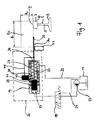
- Fig. 1 shows a rail 1 in cross-section, which has a flange-like foot 3, a web 5, which extends from the foot upwards, and a rail head 7.
- the rail head 7 is arranged above the web 5.
- the rail head 7 has a top surface 9, on which the application of the wetting and / or lubricant is to be carried out by the device according to the invention.
- the device according to the invention for wetting and / or lubricating the rail head 7 is arranged laterally next to the rail 1, in particular outside the movement space of a rail vehicle traveling on the rail 1 and, for example, in a curved area.
- the device according to the invention is referred to briefly as a lubricating device.
- the lubricating device for example, eight outlets 30, as shown in Fig. 1 are shown. However, the device may also provide fewer or more outlets 30.
- each outlet from the respective nearest outlet has a fixed, predetermined distance along the rail 1 from each other, for example a distance between about 80 mm and about 170 mm, preferably between about 100 mm and about 150 mm.
- the lubricating device has a lubricant container 11 from which by means of a lubricating pump 13 lubricant and / or wetting agent (hereinafter lubricant briefly) via a 3/2-way valve 15 in a rail head 7 facing away from chamber 17 of a arranged in a drive unit 20 cylinder 19 promoted becomes.
- a rail-side chamber 23 of the cylinder 19 is connected to the lubricant reservoir 11 via a relief line 25.
- the lubricant tank side input (or output) of the rail head facing away from the chamber 17 of the cylinder 19 is further connected via the 3/2-way valve 15 to the lubricant reservoir 11 via a not running on the pump 13 return line 27.
- a movable piston 29 guided in the cylinder 19 is mechanically connected to the outlet 30 of the lubricating device such that the rail head-side end portion 33 of the outlet of the movement of the piston 29 follows.
- the rail-head-side end face 35 of the piston 29 is further connected via a return spring 37 to the opposite end face 39 of the rail head-side chamber 23 of the cylinder 19.
- a third outlet 41 of the cylinder 19 is fluidically connected to the outlet 30 via a distributor 43 and a lubricating line 45.
- outlets 30 may be connected to a manifold 43, which is preferably designed as a progressive distributor or single-line distributor.
- the drive unit 20 generally causes a movement of all outlets 30 of a lubricating device.
- a separate drive unit 20 may be provided for groups of outlets 30, in the present embodiment having eight outlets 30, e.g. for each four outlets 30, a separate drive unit 20 may be provided.
- the rail head end portion 33 of the lubricant outlet 30 is formed as a flexible pipe and is made of, for example, a plastic such as polyamide (PA).
- the rail-head-side end portion 33 is guided in a bearing block 47, which is disposed outside a light space 50.
- the light space 50 is bordered by dotted lines, while the light space 50 is in Fig. 3 and 4 outlined with a dashed line.
- the output 41 of the cylinder 19 is also free and connected to the rail head 7 facing away from the chamber 17 of the cylinder 19.
- lubricant can be conveyed via the distributor 43 and the lubricating line 45 into the rail head-side end section 33 of the outlet 30, precisely in the period in which the outlet 30 is arranged in the second, active position.
- the lubrication line 45 is also movable and flexible due to the mobility of the outlet 30 and has a sufficient length to follow the movement of the outlet 30.
- the 3/2-way valve 15 switches.
- the pump 13 has thereby no connection with the chamber 17 of the cylinder 19 more. Due to the lack of pump pressure, the piston 29 by the force of the return spring 37 in the in Fig. 1 shown initial state moves back. The excess, in the direction away from the rail head 7 chamber 17 existing lubricant is passed back via the 3/2-way valve 15 and the return line 27 into the lubricant reservoir 11.
- FIG. 3 and 4 illustrated second embodiment is substantially analogous to the first embodiment, which in Fig. 1 and 2 is shown built up.
- Like reference numerals are assigned to elements of the device or the rail with the same function.
- the rail head-side end portion 33 of the outlet 30 is displaced together with the bearing block 47 'via a feed path c between the first and the second position.
- the bearing block 47 ' moves, for example, on a guide 48, which may be formed as a rail along the feed path c between the drive means 20 and a stop block 46 outside the light space 50.
- a return spring 49 which between bearing block 47 'and the stop block 46 is arranged, the movement of the bearing block 47' counteract.
- This in Fig. 3 and 4 arranged in the discharge line 25 '2/2-way valve 26 is used in conjunction with the distribution of the lubricant by means of progressive distributor to reduce the residual pressure before the progressive distributor as quickly as possible, so that hunting of the progressive distributor prevented and leakage of lubricant in the rest position is avoided ,
- the 2/2-way valve 26 may be provided accordingly in the first embodiment, especially if this includes a progressive distributor. If the device according to the invention does not comprise a progressive distributor, this valve can also be dispensed with.
- a monitoring device is further provided, which the position of the rail head side end portion 33, for example, the front tip, (in the case of the first embodiment of FIG Fig. 1 and 2 ) or the bearing block 47 '(in the case of the second embodiment according to FIG Fig. 3 and 4 ) supervised.
- an optical position detection be provided.
- an electrical / electronic position detection which is arranged for example in the guide 48, can be used.
Landscapes
- Engineering & Computer Science (AREA)
- Mechanical Engineering (AREA)
- Architecture (AREA)
- Civil Engineering (AREA)
- Structural Engineering (AREA)
- General Engineering & Computer Science (AREA)
- Bearings For Parts Moving Linearly (AREA)
- General Details Of Gearings (AREA)
- Lift-Guide Devices, And Elevator Ropes And Cables (AREA)
- Machines For Laying And Maintaining Railways (AREA)
- Vehicle Cleaning, Maintenance, Repair, Refitting, And Outriggers (AREA)
- Railway Tracks (AREA)
Applications Claiming Priority (1)
| Application Number | Priority Date | Filing Date | Title |
|---|---|---|---|
| DE202011103633U DE202011103633U1 (de) | 2011-07-25 | 2011-07-25 | Vorrichtung zum Benetzen oder Schmieren eines Schienenkopfs |
Publications (3)
| Publication Number | Publication Date |
|---|---|
| EP2551171A2 true EP2551171A2 (fr) | 2013-01-30 |
| EP2551171A3 EP2551171A3 (fr) | 2013-07-03 |
| EP2551171B1 EP2551171B1 (fr) | 2014-09-03 |
Family
ID=45020507
Family Applications (1)
| Application Number | Title | Priority Date | Filing Date |
|---|---|---|---|
| EP12176571.3A Active EP2551171B1 (fr) | 2011-07-25 | 2012-07-16 | Dispositif d'humidification ou de lubrification d'une tête de rail |
Country Status (12)
| Country | Link |
|---|---|
| US (1) | US9016436B2 (fr) |
| EP (1) | EP2551171B1 (fr) |
| JP (1) | JP6004426B2 (fr) |
| KR (1) | KR20130012558A (fr) |
| CN (1) | CN102897189A (fr) |
| BR (1) | BR102012018373A2 (fr) |
| CA (1) | CA2783097A1 (fr) |
| DE (1) | DE202011103633U1 (fr) |
| EA (1) | EA201200953A1 (fr) |
| ES (1) | ES2524149T3 (fr) |
| MX (1) | MX2012008628A (fr) |
| TW (1) | TW201309521A (fr) |
Families Citing this family (8)
| Publication number | Priority date | Publication date | Assignee | Title |
|---|---|---|---|---|
| US11794794B2 (en) | 2012-02-16 | 2023-10-24 | Rbl, Inc. | Rail road track lubrication apparatus and method |
| WO2013123336A1 (fr) * | 2012-02-16 | 2013-08-22 | Rbl, Inc. | Appareil et procédé de lubrification de voie ferrée |
| US10173700B2 (en) | 2013-01-07 | 2019-01-08 | Whitmore Manufacturing, Llc | Top of rail applicator and method of using the same |
| US10960907B2 (en) | 2013-01-07 | 2021-03-30 | Whitmore Manufacturing, Llc | Top of rail applicator |
| US10408212B2 (en) * | 2014-05-21 | 2019-09-10 | Circor Pumps North America, Llc | Gear pump having through-shaft bearing weepage control |
| GB2563082A (en) * | 2017-06-02 | 2018-12-05 | Roland Norman Phillips | Rail damping system |
| CN112361197B (zh) * | 2020-11-03 | 2021-08-10 | 青岛盘古智能制造股份有限公司 | 一种固定式轨道润滑系统及其控制方法 |
| US12134414B2 (en) * | 2022-05-25 | 2024-11-05 | Rbl, Inc. | Automatic switch plate lubrication assembly |
Citations (1)
| Publication number | Priority date | Publication date | Assignee | Title |
|---|---|---|---|---|
| DE102004060804A1 (de) | 2004-12-17 | 2006-07-06 | Moklansa Gmbh | Schienenschmier- und Benetzungsvorrichtung |
Family Cites Families (15)
| Publication number | Priority date | Publication date | Assignee | Title |
|---|---|---|---|---|
| US1923449A (en) | 1928-12-29 | 1933-08-22 | Railway Maintenance Corp | Lubricator |
| US1899767A (en) | 1929-04-26 | 1933-02-28 | Railway Maintenance Corp | Lubricator |
| GB2004955B (en) * | 1977-09-30 | 1982-05-26 | Swedish Rail System Ab Srs | Method and apparatus for dispensing a working substance such as a lubricant |
| CN2036545U (zh) * | 1988-09-20 | 1989-04-26 | 济南铁路局科学技术研究所 | 轨道涂油器 |
| US5305853A (en) * | 1992-09-18 | 1994-04-26 | Century Lubricants Co. | Lubricant stick applicator |
| AT409844B (de) * | 1999-07-21 | 2002-11-25 | Gunacker Richard | Verfahren und vorrichtung zum schmieren eines eisenbahnvignolgeleises |
| DE29916916U1 (de) * | 1999-09-27 | 2000-01-20 | perma-tec GmbH & Co. KG, 97717 Euerdorf | Schmiervorrichtung |
| US6854563B2 (en) * | 2001-12-17 | 2005-02-15 | General Electric Company | Wayside rail lubrication apparatus and method |
| US6742624B2 (en) | 2002-01-29 | 2004-06-01 | Lincoln Industrial Corporation | Railroad rail lubricating apparatus |
| WO2003106240A1 (fr) * | 2002-06-13 | 2003-12-24 | Portec, Rail Products Ltd. | Systeme de commande numerique de gestion de friction de cote de voie de chemin de fer |
| DE602006008506D1 (de) | 2006-03-28 | 2009-09-24 | Mazzi Tecnology S R L | Schmiervorrichtung für eisenbahnschienen |
| GB0702232D0 (en) * | 2007-02-06 | 2007-03-14 | Sutton Charles W | Grease distribution bar |
| GB2446504B (en) * | 2007-02-06 | 2008-12-31 | Charles William Sutton | Grease distribution bar |
| US8584804B2 (en) * | 2007-06-27 | 2013-11-19 | Lincoln Industrial Corporation | Apparatus for applying a pumpable material to a rail head |
| US20090000869A1 (en) * | 2007-06-27 | 2009-01-01 | Lincoln Industrial Corporation | Apparatus for Applying a Pumpable Material to a Rail Head |
-
2011
- 2011-07-25 DE DE202011103633U patent/DE202011103633U1/de not_active Expired - Lifetime
-
2012
- 2012-06-20 JP JP2012138940A patent/JP6004426B2/ja not_active Expired - Fee Related
- 2012-06-27 TW TW101122905A patent/TW201309521A/zh unknown
- 2012-07-13 CA CA2783097A patent/CA2783097A1/fr not_active Abandoned
- 2012-07-16 EP EP12176571.3A patent/EP2551171B1/fr active Active
- 2012-07-16 ES ES12176571.3T patent/ES2524149T3/es active Active
- 2012-07-23 KR KR1020120080059A patent/KR20130012558A/ko not_active Withdrawn
- 2012-07-24 EA EA201200953A patent/EA201200953A1/ru unknown
- 2012-07-24 BR BR102012018373-0A patent/BR102012018373A2/pt not_active IP Right Cessation
- 2012-07-24 US US13/556,361 patent/US9016436B2/en active Active
- 2012-07-25 CN CN2012102608652A patent/CN102897189A/zh active Pending
- 2012-07-25 MX MX2012008628A patent/MX2012008628A/es not_active Application Discontinuation
Patent Citations (1)
| Publication number | Priority date | Publication date | Assignee | Title |
|---|---|---|---|---|
| DE102004060804A1 (de) | 2004-12-17 | 2006-07-06 | Moklansa Gmbh | Schienenschmier- und Benetzungsvorrichtung |
Also Published As
| Publication number | Publication date |
|---|---|
| EP2551171B1 (fr) | 2014-09-03 |
| TW201309521A (zh) | 2013-03-01 |
| KR20130012558A (ko) | 2013-02-04 |
| JP2013032140A (ja) | 2013-02-14 |
| BR102012018373A2 (pt) | 2013-11-26 |
| US9016436B2 (en) | 2015-04-28 |
| JP6004426B2 (ja) | 2016-10-05 |
| MX2012008628A (es) | 2013-01-24 |
| EP2551171A3 (fr) | 2013-07-03 |
| ES2524149T3 (es) | 2014-12-04 |
| EA201200953A1 (ru) | 2013-04-30 |
| US20130025972A1 (en) | 2013-01-31 |
| CA2783097A1 (fr) | 2013-01-25 |
| DE202011103633U1 (de) | 2011-10-24 |
| CN102897189A (zh) | 2013-01-30 |
Similar Documents
| Publication | Publication Date | Title |
|---|---|---|
| EP2551171B1 (fr) | Dispositif d'humidification ou de lubrification d'une tête de rail | |
| EP3031693A1 (fr) | Châssis à écartement forcé pour un véhicule sur rail et véhicule sur rail doté d'un tel châssis | |
| EP2762377B1 (fr) | Châssis avec roue commandée | |
| EP2986482A1 (fr) | Châssis pourvu d'ensembles roue couplés transversalement | |
| DE922110C (de) | Schienenschmiervorrichtung | |
| AT502800B1 (de) | Lagerung einer drehstabfeder des antiwanksystems eines schienenfahrzeuges | |
| DE102020100669A1 (de) | Lineares Transportsystem sowie Motormodul und Führungsschiene für ein solches lineares Transportsystem | |
| DE102015012757A1 (de) | Schienenführungseinrichtung für Zweiwegefahrzeuge | |
| DE2353912B2 (de) | Spurkranz-schmiereinrichtung an einem schienenfahrzeug | |
| DE2617993A1 (de) | Verfahren und vorrichtung zur spurkranzschmierung beim schienengebundenen verkehr | |
| EP2518344B1 (fr) | Introduction de lubrifiant pour un guidage linéaire | |
| DE102011115634B4 (de) | Teleskopausleger | |
| EP0516972B1 (fr) | Dispositif d'amortisseur synchrone | |
| EP2353961A1 (fr) | Bogie pour un véhicule sur rail | |
| DE602006000115T2 (de) | Spannungsblockvorrichtung und elektrostatisches Beschichtungssystem mit dieser Spannungsblockvorrichtung | |
| EP3323691B1 (fr) | Dispositif d'alimentation d'un véhicule ferroviaire et procédé de fabrication dudit dispositif | |
| DE202010018220U1 (de) | Schmiervorrichtung für eine Radlenkervorrichtung | |
| DE102019126363A1 (de) | Vorrichtung zum einbringen von sand, schienenfahrzeug und verfahren zum betreiben einer vorrichtung zum einbringen von sand | |
| EP2544939A1 (fr) | Dispositif destiné à limiter un mouvement de tangage de véhicules ferroviaires | |
| DE102019130210B4 (de) | Kolbenverdichter mit Energiespareinrichtung | |
| DE2000747C3 (de) | Vorrichtung zur Übertragung der Zug-und Bremskräfte zwischen einem Drehgestell und dem Hauptrahmen von Drehgestell-Schienenfahrzeugen | |
| DE102018116624A1 (de) | Förderanlage sowie Verfahren zur Steuerung einer solchen | |
| DE102022121637A1 (de) | Luftlose Schmiermittelanlage | |
| DE19936565A1 (de) | Spurgeführtes Fahrzeug, insbesondere Schienenfahrzeug für den Nahverkehr | |
| DE102004060804A1 (de) | Schienenschmier- und Benetzungsvorrichtung |
Legal Events
| Date | Code | Title | Description |
|---|---|---|---|
| PUAI | Public reference made under article 153(3) epc to a published international application that has entered the european phase |
Free format text: ORIGINAL CODE: 0009012 |
|
| AK | Designated contracting states |
Kind code of ref document: A2 Designated state(s): AL AT BE BG CH CY CZ DE DK EE ES FI FR GB GR HR HU IE IS IT LI LT LU LV MC MK MT NL NO PL PT RO RS SE SI SK SM TR |
|
| AX | Request for extension of the european patent |
Extension state: BA ME |
|
| PUAL | Search report despatched |
Free format text: ORIGINAL CODE: 0009013 |
|
| AK | Designated contracting states |
Kind code of ref document: A3 Designated state(s): AL AT BE BG CH CY CZ DE DK EE ES FI FR GB GR HR HU IE IS IT LI LT LU LV MC MK MT NL NO PL PT RO RS SE SI SK SM TR |
|
| AX | Request for extension of the european patent |
Extension state: BA ME |
|
| RIC1 | Information provided on ipc code assigned before grant |
Ipc: E01B 19/00 20060101ALI20130527BHEP Ipc: B61K 3/00 20060101AFI20130527BHEP |
|
| 17P | Request for examination filed |
Effective date: 20140102 |
|
| RBV | Designated contracting states (corrected) |
Designated state(s): AL AT BE BG CH CY CZ DE DK EE ES FI FR GB GR HR HU IE IS IT LI LT LU LV MC MK MT NL NO PL PT RO RS SE SI SK SM TR |
|
| GRAP | Despatch of communication of intention to grant a patent |
Free format text: ORIGINAL CODE: EPIDOSNIGR1 |
|
| RIN1 | Information on inventor provided before grant (corrected) |
Inventor name: PALUNCIC, ZDRAVKO Inventor name: MANDERA, MARKUS |
|
| INTG | Intention to grant announced |
Effective date: 20140326 |
|
| GRAS | Grant fee paid |
Free format text: ORIGINAL CODE: EPIDOSNIGR3 |
|
| GRAA | (expected) grant |
Free format text: ORIGINAL CODE: 0009210 |
|
| AK | Designated contracting states |
Kind code of ref document: B1 Designated state(s): AL AT BE BG CH CY CZ DE DK EE ES FI FR GB GR HR HU IE IS IT LI LT LU LV MC MK MT NL NO PL PT RO RS SE SI SK SM TR |
|
| REG | Reference to a national code |
Ref country code: GB Ref legal event code: FG4D Free format text: NOT ENGLISH |
|
| REG | Reference to a national code |
Ref country code: CH Ref legal event code: EP Ref country code: AT Ref legal event code: REF Ref document number: 685413 Country of ref document: AT Kind code of ref document: T Effective date: 20140915 |
|
| REG | Reference to a national code |
Ref country code: IE Ref legal event code: FG4D Free format text: LANGUAGE OF EP DOCUMENT: GERMAN |
|
| REG | Reference to a national code |
Ref country code: DE Ref legal event code: R096 Ref document number: 502012001193 Country of ref document: DE Effective date: 20141016 |
|
| REG | Reference to a national code |
Ref country code: CH Ref legal event code: PFA Owner name: SKF LUBRICATION SYSTEMS GERMANY GMBH, DE Free format text: FORMER OWNER: SKF LUBRICATION SYSTEMS GERMANY AG, DE Ref country code: CH Ref legal event code: NV Representative=s name: ISLER AND PEDRAZZINI AG, CH |
|
| REG | Reference to a national code |
Ref country code: DE Ref legal event code: R082 Ref document number: 502012001193 Country of ref document: DE Representative=s name: KEIL & SCHAAFHAUSEN PATENT- UND RECHTSANWAELTE, DE |
|
| REG | Reference to a national code |
Ref country code: ES Ref legal event code: FG2A Ref document number: 2524149 Country of ref document: ES Kind code of ref document: T3 Effective date: 20141204 |
|
| RAP2 | Party data changed (patent owner data changed or rights of a patent transferred) |
Owner name: SKF LUBRICATION SYSTEMS GERMANY AG |
|
| REG | Reference to a national code |
Ref country code: SE Ref legal event code: TRGR |
|
| RAP2 | Party data changed (patent owner data changed or rights of a patent transferred) |
Owner name: SKF LUBRICATION SYSTEMS GERMANY GMBH |
|
| REG | Reference to a national code |
Ref country code: SE Ref legal event code: RPOT |
|
| REG | Reference to a national code |
Ref country code: NL Ref legal event code: T3 |
|
| REG | Reference to a national code |
Ref country code: DE Ref legal event code: R081 Ref document number: 502012001193 Country of ref document: DE Owner name: SKF LUBRICATION SYSTEMS GERMANY GMBH, DE Free format text: FORMER OWNER: LINCOLN GMBH, 69190 WALLDORF, DE Effective date: 20141202 Ref country code: DE Ref legal event code: R082 Ref document number: 502012001193 Country of ref document: DE Representative=s name: KEIL & SCHAAFHAUSEN PATENT- UND RECHTSANWAELTE, DE Effective date: 20141202 |
|
| PG25 | Lapsed in a contracting state [announced via postgrant information from national office to epo] |
Ref country code: LT Free format text: LAPSE BECAUSE OF FAILURE TO SUBMIT A TRANSLATION OF THE DESCRIPTION OR TO PAY THE FEE WITHIN THE PRESCRIBED TIME-LIMIT Effective date: 20140903 Ref country code: FI Free format text: LAPSE BECAUSE OF FAILURE TO SUBMIT A TRANSLATION OF THE DESCRIPTION OR TO PAY THE FEE WITHIN THE PRESCRIBED TIME-LIMIT Effective date: 20140903 Ref country code: GR Free format text: LAPSE BECAUSE OF FAILURE TO SUBMIT A TRANSLATION OF THE DESCRIPTION OR TO PAY THE FEE WITHIN THE PRESCRIBED TIME-LIMIT Effective date: 20141204 Ref country code: NO Free format text: LAPSE BECAUSE OF FAILURE TO SUBMIT A TRANSLATION OF THE DESCRIPTION OR TO PAY THE FEE WITHIN THE PRESCRIBED TIME-LIMIT Effective date: 20141203 |
|
| REG | Reference to a national code |
Ref country code: LT Ref legal event code: MG4D |
|
| PG25 | Lapsed in a contracting state [announced via postgrant information from national office to epo] |
Ref country code: CY Free format text: LAPSE BECAUSE OF FAILURE TO SUBMIT A TRANSLATION OF THE DESCRIPTION OR TO PAY THE FEE WITHIN THE PRESCRIBED TIME-LIMIT Effective date: 20140903 Ref country code: LV Free format text: LAPSE BECAUSE OF FAILURE TO SUBMIT A TRANSLATION OF THE DESCRIPTION OR TO PAY THE FEE WITHIN THE PRESCRIBED TIME-LIMIT Effective date: 20140903 Ref country code: RS Free format text: LAPSE BECAUSE OF FAILURE TO SUBMIT A TRANSLATION OF THE DESCRIPTION OR TO PAY THE FEE WITHIN THE PRESCRIBED TIME-LIMIT Effective date: 20140903 Ref country code: HR Free format text: LAPSE BECAUSE OF FAILURE TO SUBMIT A TRANSLATION OF THE DESCRIPTION OR TO PAY THE FEE WITHIN THE PRESCRIBED TIME-LIMIT Effective date: 20140903 |
|
| PG25 | Lapsed in a contracting state [announced via postgrant information from national office to epo] |
Ref country code: EE Free format text: LAPSE BECAUSE OF FAILURE TO SUBMIT A TRANSLATION OF THE DESCRIPTION OR TO PAY THE FEE WITHIN THE PRESCRIBED TIME-LIMIT Effective date: 20140903 Ref country code: PT Free format text: LAPSE BECAUSE OF FAILURE TO SUBMIT A TRANSLATION OF THE DESCRIPTION OR TO PAY THE FEE WITHIN THE PRESCRIBED TIME-LIMIT Effective date: 20150105 Ref country code: CZ Free format text: LAPSE BECAUSE OF FAILURE TO SUBMIT A TRANSLATION OF THE DESCRIPTION OR TO PAY THE FEE WITHIN THE PRESCRIBED TIME-LIMIT Effective date: 20140903 Ref country code: RO Free format text: LAPSE BECAUSE OF FAILURE TO SUBMIT A TRANSLATION OF THE DESCRIPTION OR TO PAY THE FEE WITHIN THE PRESCRIBED TIME-LIMIT Effective date: 20140903 Ref country code: SK Free format text: LAPSE BECAUSE OF FAILURE TO SUBMIT A TRANSLATION OF THE DESCRIPTION OR TO PAY THE FEE WITHIN THE PRESCRIBED TIME-LIMIT Effective date: 20140903 Ref country code: IS Free format text: LAPSE BECAUSE OF FAILURE TO SUBMIT A TRANSLATION OF THE DESCRIPTION OR TO PAY THE FEE WITHIN THE PRESCRIBED TIME-LIMIT Effective date: 20150103 |
|
| PG25 | Lapsed in a contracting state [announced via postgrant information from national office to epo] |
Ref country code: PL Free format text: LAPSE BECAUSE OF FAILURE TO SUBMIT A TRANSLATION OF THE DESCRIPTION OR TO PAY THE FEE WITHIN THE PRESCRIBED TIME-LIMIT Effective date: 20140903 |
|
| REG | Reference to a national code |
Ref country code: DE Ref legal event code: R097 Ref document number: 502012001193 Country of ref document: DE |
|
| REG | Reference to a national code |
Ref country code: FR Ref legal event code: PLFP Year of fee payment: 4 |
|
| PLBE | No opposition filed within time limit |
Free format text: ORIGINAL CODE: 0009261 |
|
| STAA | Information on the status of an ep patent application or granted ep patent |
Free format text: STATUS: NO OPPOSITION FILED WITHIN TIME LIMIT |
|
| PG25 | Lapsed in a contracting state [announced via postgrant information from national office to epo] |
Ref country code: DK Free format text: LAPSE BECAUSE OF FAILURE TO SUBMIT A TRANSLATION OF THE DESCRIPTION OR TO PAY THE FEE WITHIN THE PRESCRIBED TIME-LIMIT Effective date: 20140903 |
|
| 26N | No opposition filed |
Effective date: 20150604 |
|
| PGFP | Annual fee paid to national office [announced via postgrant information from national office to epo] |
Ref country code: FR Payment date: 20150626 Year of fee payment: 4 |
|
| PGFP | Annual fee paid to national office [announced via postgrant information from national office to epo] |
Ref country code: NL Payment date: 20150721 Year of fee payment: 4 |
|
| PGFP | Annual fee paid to national office [announced via postgrant information from national office to epo] |
Ref country code: ES Payment date: 20150728 Year of fee payment: 4 Ref country code: CH Payment date: 20150721 Year of fee payment: 4 |
|
| PG25 | Lapsed in a contracting state [announced via postgrant information from national office to epo] |
Ref country code: SI Free format text: LAPSE BECAUSE OF FAILURE TO SUBMIT A TRANSLATION OF THE DESCRIPTION OR TO PAY THE FEE WITHIN THE PRESCRIBED TIME-LIMIT Effective date: 20140903 |
|
| PGFP | Annual fee paid to national office [announced via postgrant information from national office to epo] |
Ref country code: BE Payment date: 20150721 Year of fee payment: 4 Ref country code: SE Payment date: 20150721 Year of fee payment: 4 |
|
| PGFP | Annual fee paid to national office [announced via postgrant information from national office to epo] |
Ref country code: IT Payment date: 20150731 Year of fee payment: 4 |
|
| PG25 | Lapsed in a contracting state [announced via postgrant information from national office to epo] |
Ref country code: MC Free format text: LAPSE BECAUSE OF FAILURE TO SUBMIT A TRANSLATION OF THE DESCRIPTION OR TO PAY THE FEE WITHIN THE PRESCRIBED TIME-LIMIT Effective date: 20140903 |
|
| PG25 | Lapsed in a contracting state [announced via postgrant information from national office to epo] |
Ref country code: LU Free format text: LAPSE BECAUSE OF FAILURE TO SUBMIT A TRANSLATION OF THE DESCRIPTION OR TO PAY THE FEE WITHIN THE PRESCRIBED TIME-LIMIT Effective date: 20150716 |
|
| REG | Reference to a national code |
Ref country code: IE Ref legal event code: MM4A |
|
| PG25 | Lapsed in a contracting state [announced via postgrant information from national office to epo] |
Ref country code: IE Free format text: LAPSE BECAUSE OF NON-PAYMENT OF DUE FEES Effective date: 20150716 |
|
| PG25 | Lapsed in a contracting state [announced via postgrant information from national office to epo] |
Ref country code: BE Free format text: LAPSE BECAUSE OF NON-PAYMENT OF DUE FEES Effective date: 20160731 |
|
| REG | Reference to a national code |
Ref country code: CH Ref legal event code: PL |
|
| REG | Reference to a national code |
Ref country code: NL Ref legal event code: MM Effective date: 20160801 |
|
| REG | Reference to a national code |
Ref country code: SE Ref legal event code: EUG |
|
| GBPC | Gb: european patent ceased through non-payment of renewal fee |
Effective date: 20160716 |
|
| PG25 | Lapsed in a contracting state [announced via postgrant information from national office to epo] |
Ref country code: MT Free format text: LAPSE BECAUSE OF FAILURE TO SUBMIT A TRANSLATION OF THE DESCRIPTION OR TO PAY THE FEE WITHIN THE PRESCRIBED TIME-LIMIT Effective date: 20140903 |
|
| PG25 | Lapsed in a contracting state [announced via postgrant information from national office to epo] |
Ref country code: FR Free format text: LAPSE BECAUSE OF NON-PAYMENT OF DUE FEES Effective date: 20160801 Ref country code: CH Free format text: LAPSE BECAUSE OF NON-PAYMENT OF DUE FEES Effective date: 20160731 Ref country code: LI Free format text: LAPSE BECAUSE OF NON-PAYMENT OF DUE FEES Effective date: 20160731 Ref country code: NL Free format text: LAPSE BECAUSE OF NON-PAYMENT OF DUE FEES Effective date: 20160801 Ref country code: SE Free format text: LAPSE BECAUSE OF NON-PAYMENT OF DUE FEES Effective date: 20160717 |
|
| REG | Reference to a national code |
Ref country code: FR Ref legal event code: ST Effective date: 20170331 |
|
| PG25 | Lapsed in a contracting state [announced via postgrant information from national office to epo] |
Ref country code: BG Free format text: LAPSE BECAUSE OF FAILURE TO SUBMIT A TRANSLATION OF THE DESCRIPTION OR TO PAY THE FEE WITHIN THE PRESCRIBED TIME-LIMIT Effective date: 20140903 Ref country code: GB Free format text: LAPSE BECAUSE OF NON-PAYMENT OF DUE FEES Effective date: 20160716 Ref country code: HU Free format text: LAPSE BECAUSE OF FAILURE TO SUBMIT A TRANSLATION OF THE DESCRIPTION OR TO PAY THE FEE WITHIN THE PRESCRIBED TIME-LIMIT; INVALID AB INITIO Effective date: 20120716 Ref country code: SM Free format text: LAPSE BECAUSE OF FAILURE TO SUBMIT A TRANSLATION OF THE DESCRIPTION OR TO PAY THE FEE WITHIN THE PRESCRIBED TIME-LIMIT Effective date: 20140903 |
|
| PG25 | Lapsed in a contracting state [announced via postgrant information from national office to epo] |
Ref country code: IT Free format text: LAPSE BECAUSE OF NON-PAYMENT OF DUE FEES Effective date: 20160716 Ref country code: TR Free format text: LAPSE BECAUSE OF FAILURE TO SUBMIT A TRANSLATION OF THE DESCRIPTION OR TO PAY THE FEE WITHIN THE PRESCRIBED TIME-LIMIT Effective date: 20140903 |
|
| PG25 | Lapsed in a contracting state [announced via postgrant information from national office to epo] |
Ref country code: ES Free format text: LAPSE BECAUSE OF NON-PAYMENT OF DUE FEES Effective date: 20160717 |
|
| REG | Reference to a national code |
Ref country code: ES Ref legal event code: FD2A Effective date: 20180626 |
|
| PG25 | Lapsed in a contracting state [announced via postgrant information from national office to epo] |
Ref country code: MK Free format text: LAPSE BECAUSE OF FAILURE TO SUBMIT A TRANSLATION OF THE DESCRIPTION OR TO PAY THE FEE WITHIN THE PRESCRIBED TIME-LIMIT Effective date: 20140903 |
|
| PG25 | Lapsed in a contracting state [announced via postgrant information from national office to epo] |
Ref country code: AL Free format text: LAPSE BECAUSE OF FAILURE TO SUBMIT A TRANSLATION OF THE DESCRIPTION OR TO PAY THE FEE WITHIN THE PRESCRIBED TIME-LIMIT Effective date: 20140903 |
|
| P01 | Opt-out of the competence of the unified patent court (upc) registered |
Effective date: 20230514 |
|
| PGFP | Annual fee paid to national office [announced via postgrant information from national office to epo] |
Ref country code: DE Payment date: 20250728 Year of fee payment: 14 |
|
| PGFP | Annual fee paid to national office [announced via postgrant information from national office to epo] |
Ref country code: AT Payment date: 20250718 Year of fee payment: 14 |