EP2551396B1 - Waschmaschine - Google Patents
Waschmaschine Download PDFInfo
- Publication number
- EP2551396B1 EP2551396B1 EP11175579.9A EP11175579A EP2551396B1 EP 2551396 B1 EP2551396 B1 EP 2551396B1 EP 11175579 A EP11175579 A EP 11175579A EP 2551396 B1 EP2551396 B1 EP 2551396B1
- Authority
- EP
- European Patent Office
- Prior art keywords
- tub
- wall
- ballast weight
- washing machine
- insert
- Prior art date
- Legal status (The legal status is an assumption and is not a legal conclusion. Google has not performed a legal analysis and makes no representation as to the accuracy of the status listed.)
- Active
Links
- 238000005406 washing Methods 0.000 title claims description 51
- 239000000463 material Substances 0.000 claims description 30
- 230000007246 mechanism Effects 0.000 claims description 14
- 239000004033 plastic Substances 0.000 claims description 5
- 229920003023 plastic Polymers 0.000 claims description 5
- XEEYBQQBJWHFJM-UHFFFAOYSA-N Iron Chemical compound [Fe] XEEYBQQBJWHFJM-UHFFFAOYSA-N 0.000 claims 2
- 238000005266 casting Methods 0.000 claims 1
- 229910052742 iron Inorganic materials 0.000 claims 1
- 238000009413 insulation Methods 0.000 description 9
- 238000001035 drying Methods 0.000 description 7
- 239000011810 insulating material Substances 0.000 description 5
- 238000004519 manufacturing process Methods 0.000 description 4
- 239000000243 solution Substances 0.000 description 4
- 229910001018 Cast iron Inorganic materials 0.000 description 3
- 239000003365 glass fiber Substances 0.000 description 3
- 238000000034 method Methods 0.000 description 3
- 229920002943 EPDM rubber Polymers 0.000 description 2
- 239000000853 adhesive Substances 0.000 description 2
- 230000001070 adhesive effect Effects 0.000 description 2
- 238000010276 construction Methods 0.000 description 2
- 238000005265 energy consumption Methods 0.000 description 2
- 230000017525 heat dissipation Effects 0.000 description 2
- 229910052500 inorganic mineral Inorganic materials 0.000 description 2
- 239000002557 mineral fiber Substances 0.000 description 2
- 238000000465 moulding Methods 0.000 description 2
- 230000021715 photosynthesis, light harvesting Effects 0.000 description 2
- 239000004743 Polypropylene Substances 0.000 description 1
- 101150114468 TUB1 gene Proteins 0.000 description 1
- 239000004964 aerogel Substances 0.000 description 1
- 239000011248 coating agent Substances 0.000 description 1
- 238000000576 coating method Methods 0.000 description 1
- 230000008878 coupling Effects 0.000 description 1
- 238000010168 coupling process Methods 0.000 description 1
- 238000005859 coupling reaction Methods 0.000 description 1
- 230000001419 dependent effect Effects 0.000 description 1
- 239000003599 detergent Substances 0.000 description 1
- 239000006185 dispersion Substances 0.000 description 1
- 239000004794 expanded polystyrene Substances 0.000 description 1
- 238000010438 heat treatment Methods 0.000 description 1
- 238000002347 injection Methods 0.000 description 1
- 239000007924 injection Substances 0.000 description 1
- 238000005304 joining Methods 0.000 description 1
- 238000010412 laundry washing Methods 0.000 description 1
- 239000007788 liquid Substances 0.000 description 1
- 238000012423 maintenance Methods 0.000 description 1
- 230000005226 mechanical processes and functions Effects 0.000 description 1
- 239000007769 metal material Substances 0.000 description 1
- 230000010355 oscillation Effects 0.000 description 1
- 229920000642 polymer Polymers 0.000 description 1
- 229920000098 polyolefin Polymers 0.000 description 1
- -1 polypropylene Polymers 0.000 description 1
- 229920001155 polypropylene Polymers 0.000 description 1
- 229920002635 polyurethane Polymers 0.000 description 1
- 239000004814 polyurethane Substances 0.000 description 1
- 239000012744 reinforcing agent Substances 0.000 description 1
- 239000012763 reinforcing filler Substances 0.000 description 1
- 229920002994 synthetic fiber Polymers 0.000 description 1
- 229920001169 thermoplastic Polymers 0.000 description 1
- XLYOFNOQVPJJNP-UHFFFAOYSA-N water Substances O XLYOFNOQVPJJNP-UHFFFAOYSA-N 0.000 description 1
- 238000003466 welding Methods 0.000 description 1
- 239000002023 wood Substances 0.000 description 1
Images
Classifications
-
- D—TEXTILES; PAPER
- D06—TREATMENT OF TEXTILES OR THE LIKE; LAUNDERING; FLEXIBLE MATERIALS NOT OTHERWISE PROVIDED FOR
- D06F—LAUNDERING, DRYING, IRONING, PRESSING OR FOLDING TEXTILE ARTICLES
- D06F37/00—Details specific to washing machines covered by groups D06F21/00 - D06F25/00
- D06F37/26—Casings; Tubs
- D06F37/265—Counterweights mounted to the tub; Mountings therefor
-
- D—TEXTILES; PAPER
- D06—TREATMENT OF TEXTILES OR THE LIKE; LAUNDERING; FLEXIBLE MATERIALS NOT OTHERWISE PROVIDED FOR
- D06F—LAUNDERING, DRYING, IRONING, PRESSING OR FOLDING TEXTILE ARTICLES
- D06F37/00—Details specific to washing machines covered by groups D06F21/00 - D06F25/00
- D06F37/26—Casings; Tubs
- D06F37/267—Tubs specially adapted for mounting thereto components or devices not provided for in preceding subgroups
Definitions
- the present invention relates to a laundry washing machine including a tub adapted for housing a rotating drum inside which the washing/drying load is placed.
- washing machine is referred both to a “standard” washing machine, adapted only for washing and rinsing the laundry, and to a washer-drier, which is adapted for washing, rinsing, and also for drying the laundry.
- a drawback of modifying/designing an appliance in order to minimize its consumption is that generally the same becomes more expensive due to the extra process steps generally required for its production and/or to a more complex structure of the appliance, and consequently the final price to be paid by the customer is higher. It is therefore critical to find a suitable compromise between the need of lowering the consumption and the final cost of the appliance, in particular it is very important that the cost should not result too high compared to the market's standards.
- a washing machine with a tub for receiving a rotatably arranged washing drum is disclosed.
- the tub is made hollow-walled or double-walled.
- the inner wall of the tub hollow body consists of a lye-resistant material. The thermal insulation is introduced into the cavity of this tub body.
- a tub for a water-bearing household appliance such as those used in drum washing machine.
- the outer drum which contains the wash process liquids has a heat insulating coating lining the inside surface with a sheet covering the surface to protect against damage by foreign bodies.
- DE 102008056555 describes a washing machine which has a drum rotatably supported in a plastic studs tub, which is provided with thermal insulation unit.
- the thermal insulation unit has shell elements forming outside hollow chambers at the suds tub, and the hollow chambers for the insulation unit are evacuated.
- the shell elements are sectionally positioned at a casing and in a lower region of the suds tub relating to an operation-appropriate position of the suds tub.
- the shell elements and/or the tub are comprised of polypropylene-glass fiber material.
- washing machines generally include counterweights, called also ballast weights, connected to the tub to increase the inertia force of the latter in order to compensate for the forces to which the tub is subjected during rotation of the drum in the washing and spin phases.
- a washing solution tub for a drum-type washing machine which includes a ballast weight which includes an elongated opening at least on the outer side ends and in the region of the apex.
- the openings on the outer side ends of the ballast weight are orientated horizontally, and the opening in the region of the apex is orientated vertically.
- a cavity between each spigot formed on the tub wall and the respective opening enables positioning of the ballast weight on the tub wall.
- US 2009229317 describes a domestic appliance including a detergent solution container having at least one first contact surface; and at least one ballast weight having at least one second contact surface mechanically connected to the first contact surface wherein the first contact surface and the second contact surface are glued to one another. At least one depression is formed on the first contact surface or the second contact surface for collecting a certain supply of adhesive mass, in order for it to be possible for a sufficient supply of adhesive to be kept available during joining.
- WO2005113879 discloses a washing and drying machine including a case, a tub provided within the case, a drum rotatably provided within the tub, a condensing duct connected to the tub and sucking air of the tub therein to condense the sucked-in air, and a drying duct connected to a front portion of the tub and the condensing duct to supply dry and hot air to the tub. It also discloses a method of manufacturing a drum of washing and drying machine, comprising the steps of forming a plurality of holes at a front portion of the drum of the washing and drying machine, and removing a plurality of burrs of the plurality of holes, respectively.
- ballast weights fixed on the tub of the appliance increases the thermal energy dissipation of the tub, due to their relatively high mass. This aspect has been non fully considered and appreciated in the known appliances' construction design.
- Applicant has found that providing an insert of insulating material between the tub and the ballast weight considerably saves energy in the heating and maintenance phases of the washing cycle by reducing thermal energy dispersions.
- a washing machine tub a tub suitable to be installed on a washing machines is meant, more generally machines in which in at least a phase of their working cycle heat dissipation takes place.
- the washing machine according to the present invention can be either of the front-loading type or of the top-loading type.
- the washing machine considered in the present invention are those provided with a tub on which at least a ballast weight is connected to.
- the tub can be realized in any material, preferably it is realized in polymeric materials; even more preferably the tub is a molded polymeric tub formed generally by several parts, for example shells, which are joined together by any suitable means forming substantially a hollow cylinder.
- the tub therefore defines a front side and a back side which corresponds substantially to the two bases of the hollow cylinder. Additionally, the tub is delimited by an outer wall defining an inner and an outer surface which are opposite to each other.
- the ballast weight is also realized in any desired material, which preferably has a relatively high mass density.
- Preferred examples of the material(s) in which the ballast weight(s) is(are) realized are concrete or cast iron.
- the tub of the invention comprises one or more ballast weights, which are preferably located on the outer surface of the tub itself, more preferably in correspondence of the back and/or front side of the hollow cylinder defined by the tub.
- ballast weight - additional elements can be attached to the tub, such as elements having a mechanical functions (e.g. a bearing to which the drum shaft is rotatably connected, etc), advantageously components generally made in metallic material or cast iron. These elements can be for example co-molded with the shell or attached to it after the molding process.
- Applicant has found that energy is saved when an insert realized in a thermal insulating material is associated to the tub between the wall of the tub and the ballast weight so that the thermal energy dissipation due to the high ballast mass is minimized thanks to the presence of an insulating material which substantially reduces heat exchange between the tub's wall and the ballast mass.
- the washing machine includes at least an insert of thermal insulating material, positioned in correspondence of the ballast weight and preferably it is sandwiched between the ballast weight and a portion of the wall of the tub.
- the tub of the invention comprises a number of insert(s) equal to the number of ballast weight(s), so that an insert is associated to each ballast weight and it is located between the weight and the tub's wall.
- ballast weights are connected to the tub of the washing machine, to enhance insulation.
- a material having thermal insulating properties means in the following a material having a thermal conductivity which is lower than the thermal conductivity of the material forming the tub.
- the material having a thermal insulating property has a thermal conductivity which is also lower than the thermal conductivity of the material forming the ballast weight.
- the invention relates to a washing machine as defined in the independent claim. Preferred embodiments are defined in the dependent claims.
- the presence of the insert allows a local insulation of the wall, in particular in those areas where the heat dissipation is greater due to the presence of the ballast weight.
- the present invention can have at least one of the following preferred characteristics.
- the insert is coupled to the wall of the tub by means of the same connection mechanism that fastens the ballast weight to the wall.
- the ballast weight is fixed to the tub by means of the connection mechanism which is a mechanical fastening device.
- the mechanical connection mechanism is a clamping device that fixes the ballast weight to the wall of the tub.
- the clamping device includes a protrusion, or bushing, protruding from the wall of the tub, a hole realized into the ballast weight on which the protrusion is inserted, and a screw engaging in the bushing to fix the ballast weight.
- the insert is coupled to the wall of the tub by the clamping device which fixes the ballast weight to the wall of the tub.
- the ballast weight includes a hole through which the protrusion is inserted.
- the insert might cover a portion of the outer surface of the tub's wall which is smaller than the portion of the wall covered by the ballast weight. According to an alternative embodiment, the insert might cover a portion of the outer surface of the wall which is larger than the portion of the wall covered by the ballast weight.
- the thermal conductivity of the material forming the insert is comprised between 0.25 and 0.001 W/(mK).
- the materials forming the insert are: • EPDM (ethylene propylene diene monomer) 0,25 W/mK • FELT 0,22 W/mK
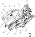
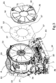
- a washing machine including a tub 10 is globally indicated with reference numeral 1.
- a tub of a top loading washing machine is depicted, it is to be understood that the teaching of the invention applies also to a front loading washing machine, and to a combined washer-dryer, both in the front loading and top loading configuration.
- the washing machine 1 includes a housing 2 which contains the tub 10 preferably supported by springs 3a and dampers 3b, in order to allow oscillations of the tub during the normal functioning of the washing machine.
- the tub 10 includes a drum 4 supported horizontally within the tub and driven by an electric motor 7, as better detailed below.
- Tub and drum have an opening 8 (shown in figures 2 and 3 , only the tub aperture is depicted) through which clothing to be washed/dried can be introduced and/or removed.
- the user can operate the washing machine 1 via a control panel 11, for example located on top of housing 2.
- Tub 10 has preferably a substantially cylindrical hollow shape and in its interior, preferably coaxially with the cylinder so defined, the tub 10 bears and houses the drum 4 which is adapted to rotate around its axis and to contain the cloths to be washed/dried in the working cycle of the machine.
- Drum and motor assembly 7 for the rotation of the same are commonly known parts in the industry and therefore not further described.
- the tub 10 additionally is delimited by a wall 25 which defines an inner surface 21 which is facing the drum, not illustrated, during operation and an outer surface 22 opposite to the inner one.
- Wall 25 comprises a envelope 27, preferably substantially cylindrical, having the two ends closed by two bases 28, 29 which results one opposite to the other.
- tub 10 can be formed by two (or more) shells fixed together, or it can be formed by several pieces such as a first piece defining the cylindrical envelope to which other two pieces forming the bases are fixed.
- the various pieces/shells forming the tub are connected to each other for example by welding.
- the connection of the various pieces/shells is watertight so that leaks do not appear during the washing or drying process of the machine in which the tub of the invention is mounted.
- tub 10 can be a single en bloc element, for example realized by a single molding step.
- tub 10, in particular wall 25, is formed in plastic material, more preferably in a polymeric material.
- the plastic wall 25 is preferably realized in a thermoplastic polymer, and even more preferably in polypropylene, to which mechanical reinforcing agents or fillers (for example mineral or glass fibers) might be added.
- a material present in the market in which the shell 20 of the invention can be realized is for example Carboran®.
- the thermal conductivity of the material forming the wall 25 of the tub 10 of the invention is generally comprised between 0.2 and 0.6 W/(mK).
- the tub 10 comprises the opening 8 in correspondence of its cylindrical envelope 27 to load and unload the clothes to be washed/dried.
- the opening 8 for the loading/unloading of the clothes is instead advantageously obtained in one of the bases 28, 29 of the tub 10.
- the tub 10 includes a ballast weight 31.
- the tub 10 of the invention can include any number of ballast weights according to the characteristics of the washing machine 1. Also the presence of a single ballast weight is encompassed by the present invention.
- ballast weight(s) 31 can be positioned in any region of the tub 10.
- ballast weight 31 is connected to the wall 25 of the tub 1, even more preferably to its outer surface 22.
- ballast weight(s) 31 is preferably located in correspondence of the base(s) 28, 29 of the hollow cylinder defined by the tub 10.
- ballast weight 31 can be realized in the same material or in different materials, they can have the same shape or different shapes one with respect to the other.
- ballast weight 31 can have a plate-like shape and its boundaries substantially follows the boundaries of the wall 25 at least for a portion of the same.
- ballast weight 31 is realized in concrete or cast iron.
- Ballast weight 31 is connected to the tub 10 by a connection mechanism 32, which preferably mechanically connects the ballast weight 31 to the wall 25.
- the connection mechanism 32 preferably comprises one or more protrusions, or bushings, 33, located advantageously on the wall 25 of the tub, more preferably projecting from the outer wall 22 of the same.
- protrusions 33 can be manufactured via plastic injection so that they form a single piece with wall 25. In the depicted embodiment, protrusions 33 project from the base 29 of the cylinder defined by the tub 10.
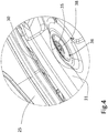
- Protrusion 33 advantageously includes a screw hole 34 where a screw 35 fits into, in order to fasten the ballast weight 31 to the tub 10 as explained in the following.
- connection mechanism 32 the whole mechanism to connect the ballast weight to the wall is meant, i.e. in the depicted drawings it includes four protrusions and four screws, however it can include an arbitrary number of protrusions and screws, or a single pair one protrusion - one screw.
- ballast weight 31 includes a through hole 36 having a preferably tapered end, i.e. the diameter of the entrance of the hole is preferably wider than the diameter inside the same.
- the screw 35 having a head 38 the diameter of which is advantageously larger than the diameter of at least a portion of through hole 36, is inserted into the through hole 36 of ballast weight 31 and then it is screwed into threaded screw hole 34. In this way, the screw 35 is screwed till the head 38 is in abutment to the hole 36 entrance and a pressure is applied to the ballast weight 31 in order to tighten the same against the wall 25.
- the tub 10 includes at least one insert 30 realized in a material having a thermal conductivity which is lower than the thermal conductivity of the material forming the tub 10.
- said thermal conductivity is comprised between 0.001 and 0.25 W/(mK).
- Preferred materials for the realization of the insert 30 are any one, or any combination, of the following: expanded or foamed polymers such as polyurethane, expanded polyolefins, expanded polystyrene, etc; or Vacuum Insulation Panels (VIP); or felts such as mineral/glass fibers, synthetic fibres, cellulosic materials, aerogels, etc; or bubble fils; or wood, etc, as long as they have insulating properties.
- the tub 10 may include a single insert 30, or a plurality of inserts of the same type (i.e. realized in the same material) or a plurality of inserts of different types (i.e. realized in different materials possibly having different thermal conductivities).
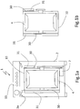
- the insert 30 is sandwiched between the wall 25 and the ballast weight 31. In other words, between wall 25 and ballast weight 31 an insert 30 is interposed.
- This interposition can be total or partial, i.e. the ballast weight can have no point of contact with the wall 25 (which is the preferred solution), or a contact can be present for a portion of the wall's surface.
- the insert 30 may advantageously follow the contour of the portion of surface 22 of wall 25 and/or of the portion of surface of ballast weight 31 to which it is in abutment.
- insert 30 can have a plate-like shape.
- the ballast weight 31 can have a surface extension broader than the surface extension of the insert 30, i.e. the insert 30 can be completely covered by the ballast weight when they are fixed to wall 25, or the insert 30 can protrude laterally from ballast weight 31.
- the insert 30 is clamped between ballast weight 31 and wall 25 via clamping means.
- clamping means preferably correspond to the connection mechanism 32 fastening the ballast weight 31 to wall 25.
- other connection mechanisms can be used, i.e. fastening means such as clamps, form-fitting coupling, snap-fitting means, hooks, etc.
- fastening means such as clamps, form-fitting coupling, snap-fitting means, hooks, etc.
- a single mechanism is used to connect both ballast weight and insert to the wall 25 of tub 10. In this way the number of parts in which the tub is realized is minimized, lowering costs and production time and complexity.
- insert 30 includes an aperture 37 through which protrusion 33 is inserted, and then screw 34 is screwed in order to fix and tighten the insert between ballast weight 31 and wall 25.
- inserts 30 are placed in correspondence of ballast weights only, additional insulating inserts 30 can be placed covering additional portions of the surface 21/22 of the wall 25. Additionally, according to a different embodiment of the invention, some ballast weights can be free of the insert 30.
- ballast weight 31 sandwiched between ballast weight 31 and the wall 25, additional elements can be present.
Landscapes
- Engineering & Computer Science (AREA)
- Textile Engineering (AREA)
- Main Body Construction Of Washing Machines And Laundry Dryers (AREA)
Claims (8)
- Waschmaschine (1), geeignet zum Waschen und Spülen der Wäsche, umfassend einen Laugenbehälter (10), der durch eine Wand (25) begrenzt ist und wenigstens ein Gegengewicht (31) umfasst, das mit der Wand (25) verbunden ist, wobei das Gegengewicht (31) in Beton- oder Eisenguss ausgeführt ist, gekennzeichnet durch das Umfassen eines Einsatzes (30), der in einem Material ausgeführt ist, das eine Wärmeleitfähigkeit aufweist, die geringer als die Wärmeleitfähigkeit des die Wand (25) bildenden Materials ist, wobei sich der Einsatz (30) zwischen der Wand (25) und dem Gegengewicht (31) befindet und einen Abschnitt einer Außenfläche der Wand (25) bedeckt, der größer als der von dem Gegengewicht (31) bedeckte Abschnitt der Wand ist.
- Waschmaschine (1) nach Anspruch 1, wobei der Einsatz (30) ein expandiertes und/oder geschäumtes Polymermaterial umfasst.
- Waschmaschine (1) nach einem der vorhergehenden Ansprüche, wobei das Gegengewicht (31) über eine Klemmvorrichtung (32), die das Gegengewicht (31) an die Wand (25) klemmt, mit der Wand (25) verbunden ist.
- Waschmaschine (1) nach einem der vorhergehenden Ansprüche, wobei das Gegengewicht (31) über einen Verbindungsmechanismus (32) mit der Wand (25) verbunden ist, wobei der Verbindungsmechanismus den Einsatz (30) zusätzlich mit der Wand (25) verbindet.
- Waschmaschine (1) nach Anspruch 4, wobei der Verbindungsmechanismus (32) einen Vorsprung (33) umfasst und das Gegengewicht (31) und der Einsatz (30) jeweils eine erste (36) beziehungsweise eine zweite Durchgangsbohrung (37) umfassen, wobei der Vorsprung (33) in die erste und die zweite Durchgangsbohrung (36, 37) eingesetzt ist.
- Waschmaschine (1) nach Anspruch 5, wobei der Vorsprung (33) ein Schraubloch (34) umfasst, auf dem eine Schraube (35) befestigt ist, wobei die Schraube (35) einen Kopf (38) umfasst, der an den Umgrenzungen einer Öffnung der zweiten Bohrung (36) anliegt.
- Waschmaschine (1) nach einem der vorhergehenden Ansprüche, wobei die Wand (25) in einem Kunststoffmaterial ausgeführt ist.
- Waschmaschine (1) nach einem der vorhergehenden Ansprüche, wobei der Einsatz (30) eine Wärmeleitfähigkeit aufweist, die geringer als die Wärmeleitfähigkeit des das Gegengewicht (31) bildenden Materials ist.
Priority Applications (1)
| Application Number | Priority Date | Filing Date | Title |
|---|---|---|---|
| EP11175579.9A EP2551396B1 (de) | 2011-07-27 | 2011-07-27 | Waschmaschine |
Applications Claiming Priority (1)
| Application Number | Priority Date | Filing Date | Title |
|---|---|---|---|
| EP11175579.9A EP2551396B1 (de) | 2011-07-27 | 2011-07-27 | Waschmaschine |
Publications (2)
| Publication Number | Publication Date |
|---|---|
| EP2551396A1 EP2551396A1 (de) | 2013-01-30 |
| EP2551396B1 true EP2551396B1 (de) | 2020-02-05 |
Family
ID=44645520
Family Applications (1)
| Application Number | Title | Priority Date | Filing Date |
|---|---|---|---|
| EP11175579.9A Active EP2551396B1 (de) | 2011-07-27 | 2011-07-27 | Waschmaschine |
Country Status (1)
| Country | Link |
|---|---|
| EP (1) | EP2551396B1 (de) |
Family Cites Families (8)
| Publication number | Priority date | Publication date | Assignee | Title |
|---|---|---|---|---|
| DE4332684A1 (de) | 1993-09-25 | 1995-03-30 | Licentia Gmbh | Waschmaschine |
| DE10018326A1 (de) * | 2000-04-11 | 2001-10-25 | Herbert Thiel | Wärmedämmung bzw. Kätleisolierung bei Waschmaschinen, Wäschetrocknern, Geschirrspülmaschinen, Eismaschinen und ähnlichen |
| DE10160788A1 (de) | 2001-12-11 | 2003-06-26 | Bsh Bosch Siemens Hausgeraete | Laugenbehälter mit einer Isolierschicht für wasserführende Haushaltgeräte |
| DE602005014858D1 (de) * | 2004-04-20 | 2009-07-23 | Lg Electronics Inc | Waschtrockner |
| DE202007002462U1 (de) * | 2006-03-14 | 2007-05-16 | BSH Bosch und Siemens Hausgeräte GmbH | Haushaltgerät mit einem Laugenbehälter |
| DE102006011734B4 (de) | 2006-03-14 | 2020-06-18 | BSH Hausgeräte GmbH | Haushaltgerät mit einem Laugenbehälter |
| DE102006052514B4 (de) | 2006-11-06 | 2010-08-05 | Miele & Cie. Kg | Laugenbehälter mit Ballastgewicht für eine Waschmaschine |
| DE102008056555B3 (de) | 2008-11-10 | 2009-12-10 | Miele & Cie. Kg | Wäschebehandlungsmaschine insbesondere Waschmaschine mit isoliertem Kunststofflaugenbehälter |
-
2011
- 2011-07-27 EP EP11175579.9A patent/EP2551396B1/de active Active
Non-Patent Citations (1)
| Title |
|---|
| None * |
Also Published As
| Publication number | Publication date |
|---|---|
| EP2551396A1 (de) | 2013-01-30 |
Similar Documents
| Publication | Publication Date | Title |
|---|---|---|
| US8151603B2 (en) | Door for washing machine | |
| KR102493055B1 (ko) | 적층식 의류 처리장치 | |
| US8047025B2 (en) | Tub for washing machine | |
| US8459148B2 (en) | Ball balancer and laundry apparatus having the same | |
| US20120007481A1 (en) | Washing Machine with Tub Having Thermally Insulating Insert | |
| US20080148785A1 (en) | Washing Machine | |
| KR20100129116A (ko) | 세탁장치 | |
| ITPN960053A1 (it) | Macchina lavabiancheria o simile con cesto rotante ad asse orizzontale | |
| EP2476795A1 (de) | Wäschetrockner | |
| CN113308842A (zh) | 堆叠式衣物处理装置 | |
| KR101537092B1 (ko) | 세탁물 처리기기 | |
| AU2006280592A1 (en) | Drying duct assembly and washing machine having the same | |
| US7204040B2 (en) | Apparatus for supplying hot air in drum type washer with dry function | |
| US20060174666A1 (en) | Tub for washing machines | |
| EP2270273B1 (de) | Waschmaschine | |
| EP2551396A1 (de) | Waschmaschine | |
| KR101162202B1 (ko) | 드럼세탁기의 터브측 운송용 볼트 체결부 구조 | |
| US20080016920A1 (en) | Drum type washing machine | |
| US8490441B2 (en) | Washing machine | |
| KR20190062050A (ko) | 의류 처리 장치 | |
| KR101071842B1 (ko) | 세탁장치 | |
| KR101033586B1 (ko) | 드럼세탁기 | |
| KR102838601B1 (ko) | 세탁기의 운송용 볼트 체결부 | |
| KR20050087454A (ko) | 건조덕트 구조 | |
| KR20070082376A (ko) | 건조겸용 드럼세탁기 |
Legal Events
| Date | Code | Title | Description |
|---|---|---|---|
| PUAI | Public reference made under article 153(3) epc to a published international application that has entered the european phase |
Free format text: ORIGINAL CODE: 0009012 |
|
| AK | Designated contracting states |
Kind code of ref document: A1 Designated state(s): AL AT BE BG CH CY CZ DE DK EE ES FI FR GB GR HR HU IE IS IT LI LT LU LV MC MK MT NL NO PL PT RO RS SE SI SK SM TR |
|
| AX | Request for extension of the european patent |
Extension state: BA ME |
|
| 17P | Request for examination filed |
Effective date: 20130730 |
|
| RBV | Designated contracting states (corrected) |
Designated state(s): AL AT BE BG CH CY CZ DE DK EE ES FI FR GB GR HR HU IE IS IT LI LT LU LV MC MK MT NL NO PL PT RO RS SE SI SK SM TR |
|
| STAA | Information on the status of an ep patent application or granted ep patent |
Free format text: STATUS: EXAMINATION IS IN PROGRESS |
|
| 17Q | First examination report despatched |
Effective date: 20180905 |
|
| GRAP | Despatch of communication of intention to grant a patent |
Free format text: ORIGINAL CODE: EPIDOSNIGR1 |
|
| STAA | Information on the status of an ep patent application or granted ep patent |
Free format text: STATUS: GRANT OF PATENT IS INTENDED |
|
| RIN1 | Information on inventor provided before grant (corrected) |
Inventor name: BONDI, MARTINO Inventor name: MAIERO, MARCO Inventor name: DE MICHIELI, ENRICO |
|
| INTG | Intention to grant announced |
Effective date: 20190828 |
|
| GRAS | Grant fee paid |
Free format text: ORIGINAL CODE: EPIDOSNIGR3 |
|
| GRAA | (expected) grant |
Free format text: ORIGINAL CODE: 0009210 |
|
| STAA | Information on the status of an ep patent application or granted ep patent |
Free format text: STATUS: THE PATENT HAS BEEN GRANTED |
|
| AK | Designated contracting states |
Kind code of ref document: B1 Designated state(s): AL AT BE BG CH CY CZ DE DK EE ES FI FR GB GR HR HU IE IS IT LI LT LU LV MC MK MT NL NO PL PT RO RS SE SI SK SM TR |
|
| REG | Reference to a national code |
Ref country code: GB Ref legal event code: FG4D |
|
| REG | Reference to a national code |
Ref country code: AT Ref legal event code: REF Ref document number: 1229968 Country of ref document: AT Kind code of ref document: T Effective date: 20200215 |
|
| REG | Reference to a national code |
Ref country code: DE Ref legal event code: R096 Ref document number: 602011064828 Country of ref document: DE |
|
| REG | Reference to a national code |
Ref country code: IE Ref legal event code: FG4D |
|
| REG | Reference to a national code |
Ref country code: CH Ref legal event code: EP |
|
| REG | Reference to a national code |
Ref country code: NL Ref legal event code: MP Effective date: 20200205 |
|
| PG25 | Lapsed in a contracting state [announced via postgrant information from national office to epo] |
Ref country code: PT Free format text: LAPSE BECAUSE OF FAILURE TO SUBMIT A TRANSLATION OF THE DESCRIPTION OR TO PAY THE FEE WITHIN THE PRESCRIBED TIME-LIMIT Effective date: 20200628 Ref country code: NO Free format text: LAPSE BECAUSE OF FAILURE TO SUBMIT A TRANSLATION OF THE DESCRIPTION OR TO PAY THE FEE WITHIN THE PRESCRIBED TIME-LIMIT Effective date: 20200505 Ref country code: FI Free format text: LAPSE BECAUSE OF FAILURE TO SUBMIT A TRANSLATION OF THE DESCRIPTION OR TO PAY THE FEE WITHIN THE PRESCRIBED TIME-LIMIT Effective date: 20200205 Ref country code: RS Free format text: LAPSE BECAUSE OF FAILURE TO SUBMIT A TRANSLATION OF THE DESCRIPTION OR TO PAY THE FEE WITHIN THE PRESCRIBED TIME-LIMIT Effective date: 20200205 |
|
| REG | Reference to a national code |
Ref country code: LT Ref legal event code: MG4D |
|
| PG25 | Lapsed in a contracting state [announced via postgrant information from national office to epo] |
Ref country code: IS Free format text: LAPSE BECAUSE OF FAILURE TO SUBMIT A TRANSLATION OF THE DESCRIPTION OR TO PAY THE FEE WITHIN THE PRESCRIBED TIME-LIMIT Effective date: 20200605 Ref country code: GR Free format text: LAPSE BECAUSE OF FAILURE TO SUBMIT A TRANSLATION OF THE DESCRIPTION OR TO PAY THE FEE WITHIN THE PRESCRIBED TIME-LIMIT Effective date: 20200506 Ref country code: LV Free format text: LAPSE BECAUSE OF FAILURE TO SUBMIT A TRANSLATION OF THE DESCRIPTION OR TO PAY THE FEE WITHIN THE PRESCRIBED TIME-LIMIT Effective date: 20200205 Ref country code: SE Free format text: LAPSE BECAUSE OF FAILURE TO SUBMIT A TRANSLATION OF THE DESCRIPTION OR TO PAY THE FEE WITHIN THE PRESCRIBED TIME-LIMIT Effective date: 20200205 Ref country code: HR Free format text: LAPSE BECAUSE OF FAILURE TO SUBMIT A TRANSLATION OF THE DESCRIPTION OR TO PAY THE FEE WITHIN THE PRESCRIBED TIME-LIMIT Effective date: 20200205 Ref country code: BG Free format text: LAPSE BECAUSE OF FAILURE TO SUBMIT A TRANSLATION OF THE DESCRIPTION OR TO PAY THE FEE WITHIN THE PRESCRIBED TIME-LIMIT Effective date: 20200505 |
|
| PG25 | Lapsed in a contracting state [announced via postgrant information from national office to epo] |
Ref country code: NL Free format text: LAPSE BECAUSE OF FAILURE TO SUBMIT A TRANSLATION OF THE DESCRIPTION OR TO PAY THE FEE WITHIN THE PRESCRIBED TIME-LIMIT Effective date: 20200205 |
|
| PG25 | Lapsed in a contracting state [announced via postgrant information from national office to epo] |
Ref country code: ES Free format text: LAPSE BECAUSE OF FAILURE TO SUBMIT A TRANSLATION OF THE DESCRIPTION OR TO PAY THE FEE WITHIN THE PRESCRIBED TIME-LIMIT Effective date: 20200205 Ref country code: DK Free format text: LAPSE BECAUSE OF FAILURE TO SUBMIT A TRANSLATION OF THE DESCRIPTION OR TO PAY THE FEE WITHIN THE PRESCRIBED TIME-LIMIT Effective date: 20200205 Ref country code: LT Free format text: LAPSE BECAUSE OF FAILURE TO SUBMIT A TRANSLATION OF THE DESCRIPTION OR TO PAY THE FEE WITHIN THE PRESCRIBED TIME-LIMIT Effective date: 20200205 Ref country code: SM Free format text: LAPSE BECAUSE OF FAILURE TO SUBMIT A TRANSLATION OF THE DESCRIPTION OR TO PAY THE FEE WITHIN THE PRESCRIBED TIME-LIMIT Effective date: 20200205 Ref country code: CZ Free format text: LAPSE BECAUSE OF FAILURE TO SUBMIT A TRANSLATION OF THE DESCRIPTION OR TO PAY THE FEE WITHIN THE PRESCRIBED TIME-LIMIT Effective date: 20200205 Ref country code: EE Free format text: LAPSE BECAUSE OF FAILURE TO SUBMIT A TRANSLATION OF THE DESCRIPTION OR TO PAY THE FEE WITHIN THE PRESCRIBED TIME-LIMIT Effective date: 20200205 Ref country code: SK Free format text: LAPSE BECAUSE OF FAILURE TO SUBMIT A TRANSLATION OF THE DESCRIPTION OR TO PAY THE FEE WITHIN THE PRESCRIBED TIME-LIMIT Effective date: 20200205 Ref country code: RO Free format text: LAPSE BECAUSE OF FAILURE TO SUBMIT A TRANSLATION OF THE DESCRIPTION OR TO PAY THE FEE WITHIN THE PRESCRIBED TIME-LIMIT Effective date: 20200205 |
|
| REG | Reference to a national code |
Ref country code: DE Ref legal event code: R097 Ref document number: 602011064828 Country of ref document: DE |
|
| REG | Reference to a national code |
Ref country code: AT Ref legal event code: MK05 Ref document number: 1229968 Country of ref document: AT Kind code of ref document: T Effective date: 20200205 |
|
| PLBE | No opposition filed within time limit |
Free format text: ORIGINAL CODE: 0009261 |
|
| STAA | Information on the status of an ep patent application or granted ep patent |
Free format text: STATUS: NO OPPOSITION FILED WITHIN TIME LIMIT |
|
| 26N | No opposition filed |
Effective date: 20201106 |
|
| PG25 | Lapsed in a contracting state [announced via postgrant information from national office to epo] |
Ref country code: AT Free format text: LAPSE BECAUSE OF FAILURE TO SUBMIT A TRANSLATION OF THE DESCRIPTION OR TO PAY THE FEE WITHIN THE PRESCRIBED TIME-LIMIT Effective date: 20200205 |
|
| PG25 | Lapsed in a contracting state [announced via postgrant information from national office to epo] |
Ref country code: MC Free format text: LAPSE BECAUSE OF FAILURE TO SUBMIT A TRANSLATION OF THE DESCRIPTION OR TO PAY THE FEE WITHIN THE PRESCRIBED TIME-LIMIT Effective date: 20200205 Ref country code: PL Free format text: LAPSE BECAUSE OF FAILURE TO SUBMIT A TRANSLATION OF THE DESCRIPTION OR TO PAY THE FEE WITHIN THE PRESCRIBED TIME-LIMIT Effective date: 20200205 Ref country code: SI Free format text: LAPSE BECAUSE OF FAILURE TO SUBMIT A TRANSLATION OF THE DESCRIPTION OR TO PAY THE FEE WITHIN THE PRESCRIBED TIME-LIMIT Effective date: 20200205 |
|
| REG | Reference to a national code |
Ref country code: CH Ref legal event code: PL |
|
| GBPC | Gb: european patent ceased through non-payment of renewal fee |
Effective date: 20200727 |
|
| REG | Reference to a national code |
Ref country code: BE Ref legal event code: MM Effective date: 20200731 |
|
| PG25 | Lapsed in a contracting state [announced via postgrant information from national office to epo] |
Ref country code: FR Free format text: LAPSE BECAUSE OF NON-PAYMENT OF DUE FEES Effective date: 20200731 Ref country code: GB Free format text: LAPSE BECAUSE OF NON-PAYMENT OF DUE FEES Effective date: 20200727 Ref country code: LU Free format text: LAPSE BECAUSE OF NON-PAYMENT OF DUE FEES Effective date: 20200727 Ref country code: LI Free format text: LAPSE BECAUSE OF NON-PAYMENT OF DUE FEES Effective date: 20200731 Ref country code: CH Free format text: LAPSE BECAUSE OF NON-PAYMENT OF DUE FEES Effective date: 20200731 |
|
| PG25 | Lapsed in a contracting state [announced via postgrant information from national office to epo] |
Ref country code: BE Free format text: LAPSE BECAUSE OF NON-PAYMENT OF DUE FEES Effective date: 20200731 |
|
| PG25 | Lapsed in a contracting state [announced via postgrant information from national office to epo] |
Ref country code: IE Free format text: LAPSE BECAUSE OF NON-PAYMENT OF DUE FEES Effective date: 20200727 |
|
| PG25 | Lapsed in a contracting state [announced via postgrant information from national office to epo] |
Ref country code: TR Free format text: LAPSE BECAUSE OF FAILURE TO SUBMIT A TRANSLATION OF THE DESCRIPTION OR TO PAY THE FEE WITHIN THE PRESCRIBED TIME-LIMIT Effective date: 20200205 Ref country code: MT Free format text: LAPSE BECAUSE OF FAILURE TO SUBMIT A TRANSLATION OF THE DESCRIPTION OR TO PAY THE FEE WITHIN THE PRESCRIBED TIME-LIMIT Effective date: 20200205 Ref country code: CY Free format text: LAPSE BECAUSE OF FAILURE TO SUBMIT A TRANSLATION OF THE DESCRIPTION OR TO PAY THE FEE WITHIN THE PRESCRIBED TIME-LIMIT Effective date: 20200205 |
|
| PG25 | Lapsed in a contracting state [announced via postgrant information from national office to epo] |
Ref country code: MK Free format text: LAPSE BECAUSE OF FAILURE TO SUBMIT A TRANSLATION OF THE DESCRIPTION OR TO PAY THE FEE WITHIN THE PRESCRIBED TIME-LIMIT Effective date: 20200205 Ref country code: AL Free format text: LAPSE BECAUSE OF FAILURE TO SUBMIT A TRANSLATION OF THE DESCRIPTION OR TO PAY THE FEE WITHIN THE PRESCRIBED TIME-LIMIT Effective date: 20200205 |
|
| PGFP | Annual fee paid to national office [announced via postgrant information from national office to epo] |
Ref country code: IT Payment date: 20220726 Year of fee payment: 12 Ref country code: DE Payment date: 20220720 Year of fee payment: 12 |
|
| P01 | Opt-out of the competence of the unified patent court (upc) registered |
Effective date: 20230625 |
|
| REG | Reference to a national code |
Ref country code: DE Ref legal event code: R119 Ref document number: 602011064828 Country of ref document: DE |
|
| PG25 | Lapsed in a contracting state [announced via postgrant information from national office to epo] |
Ref country code: DE Free format text: LAPSE BECAUSE OF NON-PAYMENT OF DUE FEES Effective date: 20240201 |
|
| PG25 | Lapsed in a contracting state [announced via postgrant information from national office to epo] |
Ref country code: IT Free format text: LAPSE BECAUSE OF NON-PAYMENT OF DUE FEES Effective date: 20230727 |