EP2551421A1 - Module photovoltaïque pouvant être installé sur une paroi verticale et/ou inclinée - Google Patents
Module photovoltaïque pouvant être installé sur une paroi verticale et/ou inclinée Download PDFInfo
- Publication number
- EP2551421A1 EP2551421A1 EP11425202A EP11425202A EP2551421A1 EP 2551421 A1 EP2551421 A1 EP 2551421A1 EP 11425202 A EP11425202 A EP 11425202A EP 11425202 A EP11425202 A EP 11425202A EP 2551421 A1 EP2551421 A1 EP 2551421A1
- Authority
- EP
- European Patent Office
- Prior art keywords
- box
- shaped body
- wall
- fixing profile
- photovoltaic module
- Prior art date
- Legal status (The legal status is an assumption and is not a legal conclusion. Google has not performed a legal analysis and makes no representation as to the accuracy of the status listed.)
- Granted
Links
- 230000002093 peripheral effect Effects 0.000 claims abstract description 3
- 238000009434 installation Methods 0.000 claims description 9
- 230000015572 biosynthetic process Effects 0.000 claims description 6
- 238000005755 formation reaction Methods 0.000 claims description 6
- 239000011248 coating agent Substances 0.000 claims description 5
- 238000000576 coating method Methods 0.000 claims description 5
- 238000000034 method Methods 0.000 claims description 2
- 230000000087 stabilizing effect Effects 0.000 claims 1
- 238000002834 transmittance Methods 0.000 description 4
- 125000006850 spacer group Chemical group 0.000 description 2
- 230000000712 assembly Effects 0.000 description 1
- 238000000429 assembly Methods 0.000 description 1
- 230000009977 dual effect Effects 0.000 description 1
- 239000011796 hollow space material Substances 0.000 description 1
- 239000000463 material Substances 0.000 description 1
Images



Classifications
-
- E—FIXED CONSTRUCTIONS
- E04—BUILDING
- E04F—FINISHING WORK ON BUILDINGS, e.g. STAIRS, FLOORS
- E04F13/00—Coverings or linings, e.g. for walls or ceilings
- E04F13/07—Coverings or linings, e.g. for walls or ceilings composed of covering or lining elements; Sub-structures therefor; Fastening means therefor
- E04F13/08—Coverings or linings, e.g. for walls or ceilings composed of covering or lining elements; Sub-structures therefor; Fastening means therefor composed of a plurality of similar covering or lining elements
- E04F13/0801—Separate fastening elements
- E04F13/0803—Separate fastening elements with load-supporting elongated furring elements between wall and covering elements
- E04F13/081—Separate fastening elements with load-supporting elongated furring elements between wall and covering elements with additional fastening elements between furring elements and covering elements
- E04F13/0821—Separate fastening elements with load-supporting elongated furring elements between wall and covering elements with additional fastening elements between furring elements and covering elements the additional fastening elements located in-between two adjacent covering elements
- E04F13/0826—Separate fastening elements with load-supporting elongated furring elements between wall and covering elements with additional fastening elements between furring elements and covering elements the additional fastening elements located in-between two adjacent covering elements engaging side grooves running along the whole length of the covering elements
-
- E—FIXED CONSTRUCTIONS
- E04—BUILDING
- E04F—FINISHING WORK ON BUILDINGS, e.g. STAIRS, FLOORS
- E04F13/00—Coverings or linings, e.g. for walls or ceilings
- E04F13/07—Coverings or linings, e.g. for walls or ceilings composed of covering or lining elements; Sub-structures therefor; Fastening means therefor
- E04F13/08—Coverings or linings, e.g. for walls or ceilings composed of covering or lining elements; Sub-structures therefor; Fastening means therefor composed of a plurality of similar covering or lining elements
- E04F13/0801—Separate fastening elements
- E04F13/0803—Separate fastening elements with load-supporting elongated furring elements between wall and covering elements
- E04F13/081—Separate fastening elements with load-supporting elongated furring elements between wall and covering elements with additional fastening elements between furring elements and covering elements
- E04F13/083—Hooking means on the back side of the covering elements
-
- E—FIXED CONSTRUCTIONS
- E04—BUILDING
- E04F—FINISHING WORK ON BUILDINGS, e.g. STAIRS, FLOORS
- E04F13/00—Coverings or linings, e.g. for walls or ceilings
- E04F13/07—Coverings or linings, e.g. for walls or ceilings composed of covering or lining elements; Sub-structures therefor; Fastening means therefor
- E04F13/08—Coverings or linings, e.g. for walls or ceilings composed of covering or lining elements; Sub-structures therefor; Fastening means therefor composed of a plurality of similar covering or lining elements
- E04F13/0889—Coverings or linings, e.g. for walls or ceilings composed of covering or lining elements; Sub-structures therefor; Fastening means therefor composed of a plurality of similar covering or lining elements characterised by the joints between neighbouring elements, e.g. with joint fillings or with tongue and groove connections
- E04F13/0898—Coverings or linings, e.g. for walls or ceilings composed of covering or lining elements; Sub-structures therefor; Fastening means therefor composed of a plurality of similar covering or lining elements characterised by the joints between neighbouring elements, e.g. with joint fillings or with tongue and groove connections with sealing elements between coverings
-
- E—FIXED CONSTRUCTIONS
- E04—BUILDING
- E04F—FINISHING WORK ON BUILDINGS, e.g. STAIRS, FLOORS
- E04F19/00—Other details of constructional parts for finishing work on buildings
- E04F19/02—Borders; Finishing strips, e.g. beadings; Light coves
- E04F19/022—Borders; Finishing strips, e.g. beadings; Light coves for use at vertical intersections of walls
- E04F19/024—Borders; Finishing strips, e.g. beadings; Light coves for use at vertical intersections of walls for outside use, e.g. imitating brickwork
-
- F—MECHANICAL ENGINEERING; LIGHTING; HEATING; WEAPONS; BLASTING
- F24—HEATING; RANGES; VENTILATING
- F24S—SOLAR HEAT COLLECTORS; SOLAR HEAT SYSTEMS
- F24S20/00—Solar heat collectors specially adapted for particular uses or environments
- F24S20/60—Solar heat collectors integrated in fixed constructions, e.g. in buildings
- F24S20/66—Solar heat collectors integrated in fixed constructions, e.g. in buildings in the form of facade constructions, e.g. wall constructions
-
- F—MECHANICAL ENGINEERING; LIGHTING; HEATING; WEAPONS; BLASTING
- F24—HEATING; RANGES; VENTILATING
- F24S—SOLAR HEAT COLLECTORS; SOLAR HEAT SYSTEMS
- F24S25/00—Arrangement of stationary mountings or supports for solar heat collector modules
- F24S25/20—Peripheral frames for modules
-
- F—MECHANICAL ENGINEERING; LIGHTING; HEATING; WEAPONS; BLASTING
- F24—HEATING; RANGES; VENTILATING
- F24S—SOLAR HEAT COLLECTORS; SOLAR HEAT SYSTEMS
- F24S25/00—Arrangement of stationary mountings or supports for solar heat collector modules
- F24S25/30—Arrangement of stationary mountings or supports for solar heat collector modules using elongate rigid mounting elements extending substantially along the supporting surface, e.g. for covering buildings with solar heat collectors
-
- F—MECHANICAL ENGINEERING; LIGHTING; HEATING; WEAPONS; BLASTING
- F24—HEATING; RANGES; VENTILATING
- F24S—SOLAR HEAT COLLECTORS; SOLAR HEAT SYSTEMS
- F24S25/00—Arrangement of stationary mountings or supports for solar heat collector modules
- F24S25/30—Arrangement of stationary mountings or supports for solar heat collector modules using elongate rigid mounting elements extending substantially along the supporting surface, e.g. for covering buildings with solar heat collectors
- F24S25/33—Arrangement of stationary mountings or supports for solar heat collector modules using elongate rigid mounting elements extending substantially along the supporting surface, e.g. for covering buildings with solar heat collectors forming substantially planar assemblies, e.g. of coplanar or stacked profiles
- F24S25/35—Arrangement of stationary mountings or supports for solar heat collector modules using elongate rigid mounting elements extending substantially along the supporting surface, e.g. for covering buildings with solar heat collectors forming substantially planar assemblies, e.g. of coplanar or stacked profiles by means of profiles with a cross-section defining separate supporting portions for adjacent modules
-
- F—MECHANICAL ENGINEERING; LIGHTING; HEATING; WEAPONS; BLASTING
- F24—HEATING; RANGES; VENTILATING
- F24S—SOLAR HEAT COLLECTORS; SOLAR HEAT SYSTEMS
- F24S25/00—Arrangement of stationary mountings or supports for solar heat collector modules
- F24S25/60—Fixation means, e.g. fasteners, specially adapted for supporting solar heat collector modules
- F24S25/61—Fixation means, e.g. fasteners, specially adapted for supporting solar heat collector modules for fixing to the ground or to building structures
-
- H—ELECTRICITY
- H02—GENERATION; CONVERSION OR DISTRIBUTION OF ELECTRIC POWER
- H02S—GENERATION OF ELECTRIC POWER BY CONVERSION OF INFRARED RADIATION, VISIBLE LIGHT OR ULTRAVIOLET LIGHT, e.g. USING PHOTOVOLTAIC [PV] MODULES
- H02S20/00—Supporting structures for PV modules
-
- H—ELECTRICITY
- H02—GENERATION; CONVERSION OR DISTRIBUTION OF ELECTRIC POWER
- H02S—GENERATION OF ELECTRIC POWER BY CONVERSION OF INFRARED RADIATION, VISIBLE LIGHT OR ULTRAVIOLET LIGHT, e.g. USING PHOTOVOLTAIC [PV] MODULES
- H02S20/00—Supporting structures for PV modules
- H02S20/20—Supporting structures directly fixed to an immovable object
- H02S20/22—Supporting structures directly fixed to an immovable object specially adapted for buildings
-
- Y—GENERAL TAGGING OF NEW TECHNOLOGICAL DEVELOPMENTS; GENERAL TAGGING OF CROSS-SECTIONAL TECHNOLOGIES SPANNING OVER SEVERAL SECTIONS OF THE IPC; TECHNICAL SUBJECTS COVERED BY FORMER USPC CROSS-REFERENCE ART COLLECTIONS [XRACs] AND DIGESTS
- Y02—TECHNOLOGIES OR APPLICATIONS FOR MITIGATION OR ADAPTATION AGAINST CLIMATE CHANGE
- Y02B—CLIMATE CHANGE MITIGATION TECHNOLOGIES RELATED TO BUILDINGS, e.g. HOUSING, HOUSE APPLIANCES OR RELATED END-USER APPLICATIONS
- Y02B10/00—Integration of renewable energy sources in buildings
- Y02B10/10—Photovoltaic [PV]
-
- Y—GENERAL TAGGING OF NEW TECHNOLOGICAL DEVELOPMENTS; GENERAL TAGGING OF CROSS-SECTIONAL TECHNOLOGIES SPANNING OVER SEVERAL SECTIONS OF THE IPC; TECHNICAL SUBJECTS COVERED BY FORMER USPC CROSS-REFERENCE ART COLLECTIONS [XRACs] AND DIGESTS
- Y02—TECHNOLOGIES OR APPLICATIONS FOR MITIGATION OR ADAPTATION AGAINST CLIMATE CHANGE
- Y02B—CLIMATE CHANGE MITIGATION TECHNOLOGIES RELATED TO BUILDINGS, e.g. HOUSING, HOUSE APPLIANCES OR RELATED END-USER APPLICATIONS
- Y02B10/00—Integration of renewable energy sources in buildings
- Y02B10/20—Solar thermal
-
- Y—GENERAL TAGGING OF NEW TECHNOLOGICAL DEVELOPMENTS; GENERAL TAGGING OF CROSS-SECTIONAL TECHNOLOGIES SPANNING OVER SEVERAL SECTIONS OF THE IPC; TECHNICAL SUBJECTS COVERED BY FORMER USPC CROSS-REFERENCE ART COLLECTIONS [XRACs] AND DIGESTS
- Y02—TECHNOLOGIES OR APPLICATIONS FOR MITIGATION OR ADAPTATION AGAINST CLIMATE CHANGE
- Y02E—REDUCTION OF GREENHOUSE GAS [GHG] EMISSIONS, RELATED TO ENERGY GENERATION, TRANSMISSION OR DISTRIBUTION
- Y02E10/00—Energy generation through renewable energy sources
- Y02E10/40—Solar thermal energy, e.g. solar towers
- Y02E10/47—Mountings or tracking
-
- Y—GENERAL TAGGING OF NEW TECHNOLOGICAL DEVELOPMENTS; GENERAL TAGGING OF CROSS-SECTIONAL TECHNOLOGIES SPANNING OVER SEVERAL SECTIONS OF THE IPC; TECHNICAL SUBJECTS COVERED BY FORMER USPC CROSS-REFERENCE ART COLLECTIONS [XRACs] AND DIGESTS
- Y02—TECHNOLOGIES OR APPLICATIONS FOR MITIGATION OR ADAPTATION AGAINST CLIMATE CHANGE
- Y02E—REDUCTION OF GREENHOUSE GAS [GHG] EMISSIONS, RELATED TO ENERGY GENERATION, TRANSMISSION OR DISTRIBUTION
- Y02E10/00—Energy generation through renewable energy sources
- Y02E10/50—Photovoltaic [PV] energy
Definitions
- the present invention refers to a photovoltaic module installed on a vertical or inclined wall.
- the specific application in particular regards the installation of photovoltaic panels on vertical or inclined walls of still existing buildings.
- the coating with the photovoltaic panels so realized has furthermore not only to architectonically integrate itself perfectly with the building, but also to possibly improve their characteristics of performance, especially in terms of thermal transmittance.
- Technical task of the invention is to provide for a photovoltaic module which obviates the drawbacks lamented in the known art.
- one purpose of the invention is to provide a photovoltaic module which can be laid with extreme easiness and versatility upon any existing structure.
- Another purpose of the invention is to provide a photovoltaic module with which a coating can be realized, which architectonically integrates itself with the building on which it is installed.
- Further purpose of the invention is to provide a photovoltaic module able to reduce the thermal transmittance of the wall on which it is installed.
- the photovoltaic module according to the invention can easily be adapted to any existing structure with vertical and/or inclined walls and architectonically integrates itself perfectly with the building upon which it is laid.
- the photovoltaic module can be pre-assembled before being laid on the wall and has a frame which precisely matches in a guided way with the fixing profile to the wall.
- the fixing system of the frame to the fixing profile is extremely simple and does not require the provision of holes and the use of screws.
- the intervention on the existing wall structure is only limited to the making of the holes for the fixing screws of the fixing profiles.
- the provision of a photovoltaic cover which modifies the thermal transmittance of the building can also advantageously determine a new energetic classification of the building itself.
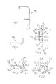
- the photovoltaic module 1 comprises a photovoltaic panel 3, a frame 4 for a peripheral support of the photovoltaic panel 3, and at least one fixing profile 5 of the frame 4 to the wall 2.
- the support frame 4 has at least a cross-beam 6 made of a profile joint with at least one profiled upright 7, and in particular has two cross-beams 6 and two uprights 7 which impart to the frame 4 a quadrangular shape.
- the upright 7 comprises a box-shaped body 8, a front angular wing 9 extending from the front limiting wall 10 of the box-shaped body 8, and a rear angular wing 11 extending from the rear wall 12 of the box-shaped body 8.
- the front angular wing 9 has a front portion 13 facing the front wall 10 of the box-shaped body 8, and a spacing portion 14 of the front portion 13 from the front wall 10 of the box-shaped body 8, so that the front wall 10 of the box-shaped body 8 limits with the front angular wing 9 an engagement seat 15 for one side of the photovoltaic panel 3.
- the front angular wing 9 is L-shaped orthogonally extending from the external edge of the front limiting wall 10 of the box-shaped body 8.
- the front angular wing 9 further extends the overall length of the upright 7.
- the rear angular wing 11 has a rear portion 16 offset from the rear wall 12 of the box-shaped body 8 and a guide portion 17 along the fixing profile 5.
- the rear angular wing 11 is L-shaped orthogonally extending from the external edge of the rear limiting wall 12 of the box-shaped body 8.
- the rear angular wing 11 extends the overall length of the upright 7.
- the spacing portion 14 being a part of the front wing 9 and the guide portion 17 being a part of the rear wing 11 are coplanar.
- the box-shaped body 8 has an internal septum 18 through which it is divided in two hollow spaces 19.
- the lateral external wall 20 of the box-shaped body 8 has for each hollow space 19, a lowered portion 21 in which a hole (not shown) is provided, which is aligned with a corresponding hole (not shown) present on the real lateral wall 22 of the box-shaped body 8 for introducing a fixing screw 23 which can be fastened in a suitable threaded bushing 24 present on the cross-beam 6.
- First engagement means are advantageously provided for the guide portion 17 present on the rear angular wing 11 with the fixing profile 5, and second engagement means for the rear portion 16 present on the rear angular wing 11 with the fixing profile 5.
- the first engagement means preferably comprise at least one profiled elongated hole 25 provided on the guide portion 17 present on the rear angular wing 11 and which can be transversally engaged by a corresponding pin 26 carried by the fixing profile 5.
- the elongated hole 25 preferably has a L-shaped angular configuration open on the rear side of the rear angular wing 11.
- the first engagement means further comprise a curved groove 27 present on the lower side of the guide portion 17 present on the rear angular wing 11 and which can be transversally engaged by a pin 28 carried by the fixing profile 5.
- the second engagement means preferably comprise at least one double eccentric element 29 which can be engaged through a groove 30 present on the fixing profile 5 for fastening the rear portion 16 of the rear angular wing 11 to the fixing profile 5.
- the element 29 in particular has a first square plate 48 and a second square 49 superimposed with the same orientation and rigidly mutually connected by means of a central spacer 50.
- the first plate 48 has two superimposed corners 51 smoother than the corners 52 of the second plate 49 to which they are superimposed. In this way the corners 52 of the second plate 49 are protruding with respect to the shape of the first plate 48.
- the fixing profile 5 preferably has a first U-shaped portion 31, and a second also U-shaped portion 32 disposed on the external side of the base 33 of the first portion 31.
- the groove 30 is made at the base 33 of the first portion 31 of the fixing profile 5.
- the pin 26 and the pin 28 are transversally carried from the opposed lateral walls 34 of the first portion 31 of the fixing profile 5.
- At least one seat 35 is defined for the engagement of a first kind of special profile 36.
- the seat 35 is made between a side wall 37 of the second portion 32 of the fixing profile 5 and an extension 38 of a side wall 34 of the first portion 31 of the fixing profile 5 from the external side of the base 33 of the first portion 31 of the fixing profile 5.
- the cross-beam 6 preferably comprises a box-shaped body 39, a front angular wing 40 extending from the front wall 41 of the box-shaped body 39 and has a front portion 42 facing the front wall 41 of the box-shaped body 39 and a spacing portion 43 of the front portion 42 of the front angular wing 40 from the front wall 41 of the box-shaped body 39, such that the front wall 41 of the box-shaped body 39 delimits with the front angular wing 40 an engagement seat 44 for one side of the photovoltaic panel 3.
- the front angular wing 40 of the cross-beam 6 is L-shaped orthogonally extending from one end of the front wall 41 of the box-shaped body 39.
- the spacing portion 43 extends coplanar with the external side wall 47 of the box-shaped body 39.
- the cross-beam 6 further has angular formations 45 for the engagement of a second kind of special profile 46.
- a first angular formation 45 of the cross-beam 6 orthogonally extends from the box-shaped body 39, and a second angular formation 45 orthogonally extends from the front angular wing 42.
- the method for the installation of photovoltaic modules 1 is briefly as follows.
- the photovoltaic modules 1 are assembled on the ground.
- the fixing profiles 5 are fastened to the wall 2 in a parallel and equally spaced position in function of the width of the support frames 4 of the photovoltaic modules 1.
- Each upright 7 is engaged with a corresponding fixing profile 5 by sliding with a rototranslatory movement the guide portion 17 of the rear angular wing 11 along the internal side of the lateral wall 34 of the fixing profile 5 until reaching the final position in which the pin 26 engages the internal end of the elongated hole 25 and the pin 28 engages the groove 27. In this position the rear portion 16 present on the rear angular wing 11 rests upon the base 33 of the fixing profile 5.
- the engagement so obtained is stabilized through the dual eccentric element 29 which is inserted with a predetermined angle through the groove 30 so passing the plate 48 through the groove 30 and positioning the spacer 50 into the groove 30, and consequently the plates 48 and 49 the one downwards and the one upwards the groove 30.
- the element 29 is rotated by means of the tip of a tool engaging a polygon footprint 53 of a conjugated shape, centrally present on the element 29. The rotation continues until the plate 48 interferes with the base 33 of the fixing profile 5 so fastening the rear portion 16 present on the rear angular wing 11 against the base 33 of the fixing profile 5.
- the coating with the modules 1 so realized is architectonically integrated with the building, creating with the wall 2 a ventilated cavity so determining a relevant reduction of the thermal transmittance of the stretched wall 2.
- the coating with the modules 1 further permits as said to make the modules 1 on the ground and their subsequent installation through simple and rapid mechanical assemblies.
- the photovoltaic module so conceived is susceptible of numerous changes and variations, all within the inventive concept; furthermore all details can be substituted with technically equivalent elements.
Landscapes
- Engineering & Computer Science (AREA)
- Architecture (AREA)
- Chemical & Material Sciences (AREA)
- Sustainable Development (AREA)
- Sustainable Energy (AREA)
- Thermal Sciences (AREA)
- Physics & Mathematics (AREA)
- Combustion & Propulsion (AREA)
- Mechanical Engineering (AREA)
- General Engineering & Computer Science (AREA)
- Life Sciences & Earth Sciences (AREA)
- Civil Engineering (AREA)
- Structural Engineering (AREA)
- Photovoltaic Devices (AREA)
- Roof Covering Using Slabs Or Stiff Sheets (AREA)
Priority Applications (1)
| Application Number | Priority Date | Filing Date | Title |
|---|---|---|---|
| EP11425202.6A EP2551421B1 (fr) | 2011-07-26 | 2011-07-26 | Module photovoltaïque pouvant être installé sur une paroi verticale et/ou inclinée |
Applications Claiming Priority (1)
| Application Number | Priority Date | Filing Date | Title |
|---|---|---|---|
| EP11425202.6A EP2551421B1 (fr) | 2011-07-26 | 2011-07-26 | Module photovoltaïque pouvant être installé sur une paroi verticale et/ou inclinée |
Publications (2)
| Publication Number | Publication Date |
|---|---|
| EP2551421A1 true EP2551421A1 (fr) | 2013-01-30 |
| EP2551421B1 EP2551421B1 (fr) | 2016-07-06 |
Family
ID=44910153
Family Applications (1)
| Application Number | Title | Priority Date | Filing Date |
|---|---|---|---|
| EP11425202.6A Not-in-force EP2551421B1 (fr) | 2011-07-26 | 2011-07-26 | Module photovoltaïque pouvant être installé sur une paroi verticale et/ou inclinée |
Country Status (1)
| Country | Link |
|---|---|
| EP (1) | EP2551421B1 (fr) |
Cited By (2)
| Publication number | Priority date | Publication date | Assignee | Title |
|---|---|---|---|---|
| EP3112552A1 (fr) * | 2015-07-03 | 2017-01-04 | Sing Tan Andy Luk | Structure de support de panneaux architectural de décoration pour montage à sec et démontage aisé, et combinaison libre de tailles |
| US10505492B2 (en) | 2016-02-12 | 2019-12-10 | Solarcity Corporation | Building integrated photovoltaic roofing assemblies and associated systems and methods |
Citations (2)
| Publication number | Priority date | Publication date | Assignee | Title |
|---|---|---|---|---|
| WO2010074701A1 (fr) * | 2008-12-03 | 2010-07-01 | Greenray, Inc. | Ensemble et procédé permettant de monter des panneaux solaires sur des surfaces de structure |
| WO2011086729A1 (fr) * | 2010-01-15 | 2011-07-21 | 菊川工業株式会社 | Structure d'installation d'articles extérieurs |
-
2011
- 2011-07-26 EP EP11425202.6A patent/EP2551421B1/fr not_active Not-in-force
Patent Citations (3)
| Publication number | Priority date | Publication date | Assignee | Title |
|---|---|---|---|---|
| WO2010074701A1 (fr) * | 2008-12-03 | 2010-07-01 | Greenray, Inc. | Ensemble et procédé permettant de monter des panneaux solaires sur des surfaces de structure |
| WO2011086729A1 (fr) * | 2010-01-15 | 2011-07-21 | 菊川工業株式会社 | Structure d'installation d'articles extérieurs |
| US20110283635A1 (en) * | 2010-01-15 | 2011-11-24 | Kikukawa Kogyo Co., Ltd. | installation structure of exterior wall decorative sheets |
Cited By (2)
| Publication number | Priority date | Publication date | Assignee | Title |
|---|---|---|---|---|
| EP3112552A1 (fr) * | 2015-07-03 | 2017-01-04 | Sing Tan Andy Luk | Structure de support de panneaux architectural de décoration pour montage à sec et démontage aisé, et combinaison libre de tailles |
| US10505492B2 (en) | 2016-02-12 | 2019-12-10 | Solarcity Corporation | Building integrated photovoltaic roofing assemblies and associated systems and methods |
Also Published As
| Publication number | Publication date |
|---|---|
| EP2551421B1 (fr) | 2016-07-06 |
Similar Documents
| Publication | Publication Date | Title |
|---|---|---|
| US7849638B2 (en) | Sunshades and methods of installing sunshades | |
| EP2895417B1 (fr) | Ascenseur | |
| CN107965072B (zh) | 单元式幕墙格栅系统的安装结构及单元式幕墙 | |
| CN101095017A (zh) | 具有螺纹滑块的安装系统 | |
| EP2551421B1 (fr) | Module photovoltaïque pouvant être installé sur une paroi verticale et/ou inclinée | |
| KR200492408Y1 (ko) | 조립식 칸막이 | |
| RU2015132610A (ru) | Крепежная система для крепления плитообразных фасадных элементов, фасадный элемент, способ монтажа плитообразных фасадных элементов, а также фасад | |
| CN112727044B (zh) | 悬挑脚手架的安装结构及其施工方法 | |
| CN202391159U (zh) | 一种活动房 | |
| WO2015067276A1 (fr) | Système de montage de façade | |
| RU2490402C2 (ru) | Конструкция для разделения помещений | |
| KR100952486B1 (ko) | 건축물 창문틀 고정부재 | |
| KR20150045807A (ko) | 오픈조인트공법용 기능성 외장마감재 고정장치 | |
| KR101072082B1 (ko) | 창호 시공을 위한 앵글유닛 | |
| EP2947237B1 (fr) | Mécanisme de fixation de panneaux pour fermeture de terrains de sport | |
| CN209082789U (zh) | 一种建筑体幕墙结构 | |
| EP2881527B1 (fr) | Système de construction pour enceinte de clôtures | |
| ITMI20091291A1 (it) | Sistema di ancoraggio di una o piu' doghe, in particolare per il rivestimento di pareti esterne di edifici, e relativo procedimento di ancoraggio doghe | |
| KR101074648B1 (ko) | 건축물지주 | |
| CN102454306A (zh) | 一种活动房 | |
| CN203213510U (zh) | 一种用于固定扭曲变形体的z字形金属爪件 | |
| RU121521U1 (ru) | Огораживающая и ограждающая конструкция (варианты) | |
| KR101627343B1 (ko) | 건축물 지붕에 다양한 형상의 상부마감판을 고정하는 패널시스템 | |
| EP2886776B1 (fr) | Poste avant pour châssis muraux de portes coulissantes rétractables | |
| CN203834953U (zh) | 空间网架反吊装结构 |
Legal Events
| Date | Code | Title | Description |
|---|---|---|---|
| PUAI | Public reference made under article 153(3) epc to a published international application that has entered the european phase |
Free format text: ORIGINAL CODE: 0009012 |
|
| 17P | Request for examination filed |
Effective date: 20120726 |
|
| AK | Designated contracting states |
Kind code of ref document: A1 Designated state(s): AL AT BE BG CH CY CZ DE DK EE ES FI FR GB GR HR HU IE IS IT LI LT LU LV MC MK MT NL NO PL PT RO RS SE SI SK SM TR |
|
| AX | Request for extension of the european patent |
Extension state: BA ME |
|
| GRAP | Despatch of communication of intention to grant a patent |
Free format text: ORIGINAL CODE: EPIDOSNIGR1 |
|
| INTG | Intention to grant announced |
Effective date: 20160204 |
|
| GRAS | Grant fee paid |
Free format text: ORIGINAL CODE: EPIDOSNIGR3 |
|
| GRAA | (expected) grant |
Free format text: ORIGINAL CODE: 0009210 |
|
| AK | Designated contracting states |
Kind code of ref document: B1 Designated state(s): AL AT BE BG CH CY CZ DE DK EE ES FI FR GB GR HR HU IE IS IT LI LT LU LV MC MK MT NL NO PL PT RO RS SE SI SK SM TR |
|
| REG | Reference to a national code |
Ref country code: GB Ref legal event code: FG4D |
|
| REG | Reference to a national code |
Ref country code: AT Ref legal event code: REF Ref document number: 810836 Country of ref document: AT Kind code of ref document: T Effective date: 20160715 Ref country code: CH Ref legal event code: EP |
|
| REG | Reference to a national code |
Ref country code: IE Ref legal event code: FG4D |
|
| REG | Reference to a national code |
Ref country code: DE Ref legal event code: R096 Ref document number: 602011027910 Country of ref document: DE |
|
| REG | Reference to a national code |
Ref country code: NL Ref legal event code: MP Effective date: 20160706 |
|
| REG | Reference to a national code |
Ref country code: LT Ref legal event code: MG4D |
|
| REG | Reference to a national code |
Ref country code: AT Ref legal event code: MK05 Ref document number: 810836 Country of ref document: AT Kind code of ref document: T Effective date: 20160706 |
|
| PG25 | Lapsed in a contracting state [announced via postgrant information from national office to epo] |
Ref country code: BE Free format text: LAPSE BECAUSE OF NON-PAYMENT OF DUE FEES Effective date: 20160731 |
|
| PG25 | Lapsed in a contracting state [announced via postgrant information from national office to epo] |
Ref country code: LT Free format text: LAPSE BECAUSE OF FAILURE TO SUBMIT A TRANSLATION OF THE DESCRIPTION OR TO PAY THE FEE WITHIN THE PRESCRIBED TIME-LIMIT Effective date: 20160706 Ref country code: HR Free format text: LAPSE BECAUSE OF FAILURE TO SUBMIT A TRANSLATION OF THE DESCRIPTION OR TO PAY THE FEE WITHIN THE PRESCRIBED TIME-LIMIT Effective date: 20160706 Ref country code: FI Free format text: LAPSE BECAUSE OF FAILURE TO SUBMIT A TRANSLATION OF THE DESCRIPTION OR TO PAY THE FEE WITHIN THE PRESCRIBED TIME-LIMIT Effective date: 20160706 Ref country code: NL Free format text: LAPSE BECAUSE OF FAILURE TO SUBMIT A TRANSLATION OF THE DESCRIPTION OR TO PAY THE FEE WITHIN THE PRESCRIBED TIME-LIMIT Effective date: 20160706 Ref country code: RS Free format text: LAPSE BECAUSE OF FAILURE TO SUBMIT A TRANSLATION OF THE DESCRIPTION OR TO PAY THE FEE WITHIN THE PRESCRIBED TIME-LIMIT Effective date: 20160706 Ref country code: IS Free format text: LAPSE BECAUSE OF FAILURE TO SUBMIT A TRANSLATION OF THE DESCRIPTION OR TO PAY THE FEE WITHIN THE PRESCRIBED TIME-LIMIT Effective date: 20161106 Ref country code: NO Free format text: LAPSE BECAUSE OF FAILURE TO SUBMIT A TRANSLATION OF THE DESCRIPTION OR TO PAY THE FEE WITHIN THE PRESCRIBED TIME-LIMIT Effective date: 20161006 |
|
| REG | Reference to a national code |
Ref country code: DE Ref legal event code: R119 Ref document number: 602011027910 Country of ref document: DE |
|
| PG25 | Lapsed in a contracting state [announced via postgrant information from national office to epo] |
Ref country code: PT Free format text: LAPSE BECAUSE OF FAILURE TO SUBMIT A TRANSLATION OF THE DESCRIPTION OR TO PAY THE FEE WITHIN THE PRESCRIBED TIME-LIMIT Effective date: 20161107 Ref country code: BE Free format text: LAPSE BECAUSE OF FAILURE TO SUBMIT A TRANSLATION OF THE DESCRIPTION OR TO PAY THE FEE WITHIN THE PRESCRIBED TIME-LIMIT Effective date: 20160706 Ref country code: SE Free format text: LAPSE BECAUSE OF FAILURE TO SUBMIT A TRANSLATION OF THE DESCRIPTION OR TO PAY THE FEE WITHIN THE PRESCRIBED TIME-LIMIT Effective date: 20160706 Ref country code: PL Free format text: LAPSE BECAUSE OF FAILURE TO SUBMIT A TRANSLATION OF THE DESCRIPTION OR TO PAY THE FEE WITHIN THE PRESCRIBED TIME-LIMIT Effective date: 20160706 Ref country code: GR Free format text: LAPSE BECAUSE OF FAILURE TO SUBMIT A TRANSLATION OF THE DESCRIPTION OR TO PAY THE FEE WITHIN THE PRESCRIBED TIME-LIMIT Effective date: 20161007 Ref country code: LV Free format text: LAPSE BECAUSE OF FAILURE TO SUBMIT A TRANSLATION OF THE DESCRIPTION OR TO PAY THE FEE WITHIN THE PRESCRIBED TIME-LIMIT Effective date: 20160706 Ref country code: ES Free format text: LAPSE BECAUSE OF FAILURE TO SUBMIT A TRANSLATION OF THE DESCRIPTION OR TO PAY THE FEE WITHIN THE PRESCRIBED TIME-LIMIT Effective date: 20160706 Ref country code: AT Free format text: LAPSE BECAUSE OF FAILURE TO SUBMIT A TRANSLATION OF THE DESCRIPTION OR TO PAY THE FEE WITHIN THE PRESCRIBED TIME-LIMIT Effective date: 20160706 |
|
| REG | Reference to a national code |
Ref country code: CH Ref legal event code: PL |
|
| PG25 | Lapsed in a contracting state [announced via postgrant information from national office to epo] |
Ref country code: DE Free format text: LAPSE BECAUSE OF NON-PAYMENT OF DUE FEES Effective date: 20170201 Ref country code: EE Free format text: LAPSE BECAUSE OF FAILURE TO SUBMIT A TRANSLATION OF THE DESCRIPTION OR TO PAY THE FEE WITHIN THE PRESCRIBED TIME-LIMIT Effective date: 20160706 Ref country code: LI Free format text: LAPSE BECAUSE OF NON-PAYMENT OF DUE FEES Effective date: 20160731 Ref country code: RO Free format text: LAPSE BECAUSE OF FAILURE TO SUBMIT A TRANSLATION OF THE DESCRIPTION OR TO PAY THE FEE WITHIN THE PRESCRIBED TIME-LIMIT Effective date: 20160706 Ref country code: CH Free format text: LAPSE BECAUSE OF NON-PAYMENT OF DUE FEES Effective date: 20160731 Ref country code: MC Free format text: LAPSE BECAUSE OF FAILURE TO SUBMIT A TRANSLATION OF THE DESCRIPTION OR TO PAY THE FEE WITHIN THE PRESCRIBED TIME-LIMIT Effective date: 20160706 |
|
| REG | Reference to a national code |
Ref country code: IE Ref legal event code: MM4A |
|
| PLBE | No opposition filed within time limit |
Free format text: ORIGINAL CODE: 0009261 |
|
| STAA | Information on the status of an ep patent application or granted ep patent |
Free format text: STATUS: NO OPPOSITION FILED WITHIN TIME LIMIT |
|
| PG25 | Lapsed in a contracting state [announced via postgrant information from national office to epo] |
Ref country code: CZ Free format text: LAPSE BECAUSE OF FAILURE TO SUBMIT A TRANSLATION OF THE DESCRIPTION OR TO PAY THE FEE WITHIN THE PRESCRIBED TIME-LIMIT Effective date: 20160706 Ref country code: SK Free format text: LAPSE BECAUSE OF FAILURE TO SUBMIT A TRANSLATION OF THE DESCRIPTION OR TO PAY THE FEE WITHIN THE PRESCRIBED TIME-LIMIT Effective date: 20160706 Ref country code: BG Free format text: LAPSE BECAUSE OF FAILURE TO SUBMIT A TRANSLATION OF THE DESCRIPTION OR TO PAY THE FEE WITHIN THE PRESCRIBED TIME-LIMIT Effective date: 20161006 Ref country code: DK Free format text: LAPSE BECAUSE OF FAILURE TO SUBMIT A TRANSLATION OF THE DESCRIPTION OR TO PAY THE FEE WITHIN THE PRESCRIBED TIME-LIMIT Effective date: 20160706 Ref country code: SM Free format text: LAPSE BECAUSE OF FAILURE TO SUBMIT A TRANSLATION OF THE DESCRIPTION OR TO PAY THE FEE WITHIN THE PRESCRIBED TIME-LIMIT Effective date: 20160706 |
|
| REG | Reference to a national code |
Ref country code: FR Ref legal event code: ST Effective date: 20170503 |
|
| 26N | No opposition filed |
Effective date: 20170407 |
|
| GBPC | Gb: european patent ceased through non-payment of renewal fee |
Effective date: 20161006 |
|
| PG25 | Lapsed in a contracting state [announced via postgrant information from national office to epo] |
Ref country code: GB Free format text: LAPSE BECAUSE OF NON-PAYMENT OF DUE FEES Effective date: 20161006 Ref country code: IE Free format text: LAPSE BECAUSE OF NON-PAYMENT OF DUE FEES Effective date: 20160726 Ref country code: FR Free format text: LAPSE BECAUSE OF NON-PAYMENT OF DUE FEES Effective date: 20160906 |
|
| PG25 | Lapsed in a contracting state [announced via postgrant information from national office to epo] |
Ref country code: SI Free format text: LAPSE BECAUSE OF FAILURE TO SUBMIT A TRANSLATION OF THE DESCRIPTION OR TO PAY THE FEE WITHIN THE PRESCRIBED TIME-LIMIT Effective date: 20160706 Ref country code: LU Free format text: LAPSE BECAUSE OF NON-PAYMENT OF DUE FEES Effective date: 20160726 |
|
| PG25 | Lapsed in a contracting state [announced via postgrant information from national office to epo] |
Ref country code: CY Free format text: LAPSE BECAUSE OF FAILURE TO SUBMIT A TRANSLATION OF THE DESCRIPTION OR TO PAY THE FEE WITHIN THE PRESCRIBED TIME-LIMIT Effective date: 20160706 Ref country code: HU Free format text: LAPSE BECAUSE OF FAILURE TO SUBMIT A TRANSLATION OF THE DESCRIPTION OR TO PAY THE FEE WITHIN THE PRESCRIBED TIME-LIMIT; INVALID AB INITIO Effective date: 20110726 |
|
| PG25 | Lapsed in a contracting state [announced via postgrant information from national office to epo] |
Ref country code: MT Free format text: LAPSE BECAUSE OF NON-PAYMENT OF DUE FEES Effective date: 20160731 Ref country code: TR Free format text: LAPSE BECAUSE OF FAILURE TO SUBMIT A TRANSLATION OF THE DESCRIPTION OR TO PAY THE FEE WITHIN THE PRESCRIBED TIME-LIMIT Effective date: 20160706 Ref country code: MK Free format text: LAPSE BECAUSE OF FAILURE TO SUBMIT A TRANSLATION OF THE DESCRIPTION OR TO PAY THE FEE WITHIN THE PRESCRIBED TIME-LIMIT Effective date: 20160706 |
|
| PGFP | Annual fee paid to national office [announced via postgrant information from national office to epo] |
Ref country code: IT Payment date: 20180618 Year of fee payment: 8 |
|
| PG25 | Lapsed in a contracting state [announced via postgrant information from national office to epo] |
Ref country code: AL Free format text: LAPSE BECAUSE OF FAILURE TO SUBMIT A TRANSLATION OF THE DESCRIPTION OR TO PAY THE FEE WITHIN THE PRESCRIBED TIME-LIMIT Effective date: 20160706 |
|
| PG25 | Lapsed in a contracting state [announced via postgrant information from national office to epo] |
Ref country code: IT Free format text: LAPSE BECAUSE OF NON-PAYMENT OF DUE FEES Effective date: 20190726 |