EP2551468B1 - Anordnung einer Schaufelspitzendichtung mit durchgangsverbundenen Hohlräumen und zugehöriges Betriebsverfahren - Google Patents
Anordnung einer Schaufelspitzendichtung mit durchgangsverbundenen Hohlräumen und zugehöriges Betriebsverfahren Download PDFInfo
- Publication number
- EP2551468B1 EP2551468B1 EP12177520.9A EP12177520A EP2551468B1 EP 2551468 B1 EP2551468 B1 EP 2551468B1 EP 12177520 A EP12177520 A EP 12177520A EP 2551468 B1 EP2551468 B1 EP 2551468B1
- Authority
- EP
- European Patent Office
- Prior art keywords
- cavity
- boas
- gas turbine
- turbine engine
- passage
- Prior art date
- Legal status (The legal status is an assumption and is not a legal conclusion. Google has not performed a legal analysis and makes no representation as to the accuracy of the status listed.)
- Active
Links
Images

Classifications
-
- F—MECHANICAL ENGINEERING; LIGHTING; HEATING; WEAPONS; BLASTING
- F01—MACHINES OR ENGINES IN GENERAL; ENGINE PLANTS IN GENERAL; STEAM ENGINES
- F01D—NON-POSITIVE DISPLACEMENT MACHINES OR ENGINES, e.g. STEAM TURBINES
- F01D11/00—Preventing or minimising internal leakage of working-fluid, e.g. between stages
- F01D11/08—Preventing or minimising internal leakage of working-fluid, e.g. between stages for sealing space between rotor blade tips and stator
- F01D11/14—Adjusting or regulating tip-clearance, i.e. distance between rotor-blade tips and stator casing
- F01D11/20—Actively adjusting tip-clearance
- F01D11/24—Actively adjusting tip-clearance by selectively cooling-heating stator or rotor components
-
- F—MECHANICAL ENGINEERING; LIGHTING; HEATING; WEAPONS; BLASTING
- F05—INDEXING SCHEMES RELATING TO ENGINES OR PUMPS IN VARIOUS SUBCLASSES OF CLASSES F01-F04
- F05D—INDEXING SCHEME FOR ASPECTS RELATING TO NON-POSITIVE-DISPLACEMENT MACHINES OR ENGINES, GAS-TURBINES OR JET-PROPULSION PLANTS
- F05D2240/00—Components
- F05D2240/10—Stators
- F05D2240/11—Shroud seal segments
-
- F—MECHANICAL ENGINEERING; LIGHTING; HEATING; WEAPONS; BLASTING
- F05—INDEXING SCHEMES RELATING TO ENGINES OR PUMPS IN VARIOUS SUBCLASSES OF CLASSES F01-F04
- F05D—INDEXING SCHEME FOR ASPECTS RELATING TO NON-POSITIVE-DISPLACEMENT MACHINES OR ENGINES, GAS-TURBINES OR JET-PROPULSION PLANTS
- F05D2260/00—Function
- F05D2260/20—Heat transfer, e.g. cooling
- F05D2260/201—Heat transfer, e.g. cooling by impingement of a fluid
-
- F—MECHANICAL ENGINEERING; LIGHTING; HEATING; WEAPONS; BLASTING
- F05—INDEXING SCHEMES RELATING TO ENGINES OR PUMPS IN VARIOUS SUBCLASSES OF CLASSES F01-F04
- F05D—INDEXING SCHEME FOR ASPECTS RELATING TO NON-POSITIVE-DISPLACEMENT MACHINES OR ENGINES, GAS-TURBINES OR JET-PROPULSION PLANTS
- F05D2260/00—Function
- F05D2260/20—Heat transfer, e.g. cooling
- F05D2260/205—Cooling fluid recirculation, i.e. after cooling one or more components is the cooling fluid recovered and used elsewhere for other purposes
-
- Y—GENERAL TAGGING OF NEW TECHNOLOGICAL DEVELOPMENTS; GENERAL TAGGING OF CROSS-SECTIONAL TECHNOLOGIES SPANNING OVER SEVERAL SECTIONS OF THE IPC; TECHNICAL SUBJECTS COVERED BY FORMER USPC CROSS-REFERENCE ART COLLECTIONS [XRACs] AND DIGESTS
- Y02—TECHNOLOGIES OR APPLICATIONS FOR MITIGATION OR ADAPTATION AGAINST CLIMATE CHANGE
- Y02T—CLIMATE CHANGE MITIGATION TECHNOLOGIES RELATED TO TRANSPORTATION
- Y02T50/00—Aeronautics or air transport
- Y02T50/60—Efficient propulsion technologies, e.g. for aircraft
Definitions
- the present application relates to a blade outer air seal (BOAS) and more particularly to a multi-cavity blade outer air seal (BOAS) in a gas turbine engine.
- BOAS blade outer air seal
- BOAS multi-cavity blade outer air seal
- Gas turbine engines generally include fan, compressor, combustor and turbine sections along an engine axis of rotation.
- the fan, compressor, and turbine sections each include a series of stator and rotor blade assemblies.
- a rotor and an axially adjacent array of stator assemblies may be referred to as a stage.
- Each stator vane assembly increases efficiency through the direction of core gas flow into or out of the rotor assemblies.
- An outer case including a multiple of blade outer air seals (BOAS), provides an outer radial flow path boundary.
- a multiple of BOAS are typically provided to accommodate thermal and dynamic variation typical in a high pressure turbine (HPT) section of the gas turbine engine.
- the BOAS are subjected to relatively high temperatures and receive a secondary cooling airflow for temperature control.
- the secondary cooling airflow is communicated into the BOAS then through cooling channels within the BOAS for temperature control.
- US 4679981 discloses a gas turbine engine having the features of the preamble of claim 1.
- US 5993150 A discloses a cooled turbine shroud.
- EP 1990507 A1 discloses an impingement cooled turbine shroud.
- Other cooled shrouds are disclosed in US 2005/0089396 A1 and US 4280792 A2 .
- the invention provides a gas turbine engine as set forth in claim 1. From a second aspect, the invention provides a method of communicating a secondary cooling airflow within a gas turbine engine as set forth in claim 5.
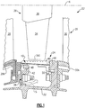
- FIG. 1 schematically illustrates a gas turbine engine 20, illustrated partially herein as a High Pressure Turbine (HPT) section 22 disposed along a common engine longitudinal axis A.
- the engine 20 includes a Blade Outer Air Seal (BOAS) assembly 24 to provide an outer core gas path seal for the turbine section 22.
- BOAS Blade Outer Air Seal
- FIG. 1 schematically illustrates a gas turbine engine 20, illustrated partially herein as a High Pressure Turbine (HPT) section 22 disposed along a common engine longitudinal axis A.
- the engine 20 includes a Blade Outer Air Seal (BOAS) assembly 24 to provide an outer core gas path seal for the turbine section 22.
- BOAS Blade Outer Air Seal
- the BOAS segment may find beneficial use in many industries including aerospace, industrial, electricity generation, naval propulsion, pumping sets for gas and oil transmission, aircraft propulsion, vehicle engines, and stationary power plants.
- the HPT section 22 generally includes a rotor assembly 26 disposed between forward and aft stationary vane assemblies 28, 30. Outer vane supports 28A, 30A attach the respective vane assemblies to an engine case 32 (illustrated schematically).
- the rotor assembly 26 generally includes a multiple of airfoils 34 circumferentially disposed around a disk 36. The distal end of each airfoil 34 may be referred to as an airfoil tip 34T which rides adjacent to the BOAS assembly 24.
- the BOAS assembly 24 is generally disposed in an annulus radially between the engine case 32 and the airfoil tips 34T.
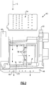
- the BOAS assembly 24 generally includes a blade outer air seal (BOAS) support 38 and a multiple of blade outer air seal (BOAS) segments 40 mountable thereto (also see Figure 2 ).
- the BOAS support 38 is mounted within the engine case 32 to define forward and aft flanges 42, 44 to receive the BOAS segments 40.
- the forward flanges 42 and the aft flanges 44 may be circumferentially segmented to receive the BOAS segments 40 in a circumferentially rotated and locked arrangement as generally understood. It should be understood that various interfaces and BOAS assemblies may alternatively be provided.
- Each BOAS segment 40 includes a body 46 which defines a forward interface 48 and an aft interface 50.
- the forward interface 48 and the aft interface 50 respectively engage the flanges 42, 44 to secure each individual BOAS segment 40 thereto.
- each BOAS segment 40 includes at least two cavities 52A, 52B to receive a secondary cooling airflow S.
- Each cavity 52A, 52B may be formed through, for example, an investment casting process then closed by a single impingement plate 54.
- the cavity 52A is axially forward of cavity 52B but separated therefrom by a circumferential rib 56. That is, the circumferential rib 56 essentially surrounds the engine longitudinal axis A. Secondary cooling air S flows through the plate 54, impinges in the BOAS cavities 52A, 52B then flows out to the core gaspath flow through a multiple of edge holes 60. The circumferential rib 56 and plate 54 isolates the secondary cooling air allocated to a specific cavity 52A, 52B. It should be understood that various alternative cavity and passageway arrangements may be provided that lie within the scope of the appended claims.
- the circumferential rib 56 includes at least two passages 58 which provides for secondary cooling air S to flow aftward from the forward cavity 52A to the aft cavity 52B.
- the term "passage” as utilized herein may include various slots, apertures, openings, holes and paths.
- three passages 58 are provided which removes approximately 3.5% of the rib 56. Since the percentage of material removed is minimal and since the removal of the material is from a circumferential member rather than an axial member, minimal, if any, structural impact is experienced by the BOAS segment 40.
- the passages 58 allow some of the forward cavity 52A secondary cooling air S to be reused in the aft cavity 52B which results in lower temperatures and relatively lower cooling flow requirements for the BOAS segment 40.
- the passages 58 also permit at least some reuse of the secondary cooling air S with the single plate 54 which needs not be welded to the rib 56.
- the single plate 54 facilitates manufacture with minimal brazing filler metal (BFM) and minimizes undesired leakage.
- the secondary cooling air S gaspath pressure within the BOAS segment 40 is lower axially aft of airfoil tips 34T ( Figure 1 ).
- the forward cavity 52A thus has a somewhat higher static pressure than the aft cavity 52B ( Figure 3 ) due to the direction of primary core flow.
Landscapes
- Engineering & Computer Science (AREA)
- Mechanical Engineering (AREA)
- General Engineering & Computer Science (AREA)
- Turbine Rotor Nozzle Sealing (AREA)
Claims (5)
- Gasturbinentriebwerk, das eine Baugruppe (24) einer äußeren Laufschaufelluftdichtung umfasst, wobei die Baugruppe Folgendes umfasst:einen Körper (46), der einen ersten Hohlraum (52A) definiert, der durch eine umlaufende Rippe (56) von einem zweiten Hohlraum (52B) getrennt ist,eine Aufprallplatte (54), die den ersten Hohlraum (52A) und den zweiten Hohlraum (52B) umschließt, wobei die Aufprallplatte (54) eine Vielzahl von Pralllöchern umfasst, die dort hindurch ausgebildet sind, wobei die Pralllöcher sich sowohl in den ersten Hohlraum (54A) als auch in den zweiten Hohlraum (52B) öffnen; dadurch gekennzeichnet, dass:die umlaufende Rippe (56) Folgendes beinhaltet: mehr als einen Durchgang (58), die eine Kommunikation zwischen dem ersten Hohlraum (52A) und dem zweiten Hohlraum (52B) bereitstellen;wobei der mehr als eine Durchgang (58) Folgendes entfernen: ungefähr 3,5 % des Materials der Rippe (56).
- Gasturbinentriebwerk nach Anspruch 1, wobei die Baugruppe drei Durchgänge (58) umfasst.
- Gasturbinentriebwerk nach Anspruch 1 oder 2, wobei der erste Hohlraum ein vorderer Hohlraum (52A) ist und der zweite Hohlraum (52B) sich axial hinter dem ersten Hohlraum befindet.
- Gasturbinentriebwerk nach einem der vorhergehenden Ansprüche, wobei der Körper (46) eine Mehrzahl von Kantenlöchern (60) umfasst, die mit dem vorderen Hohlraum (52A) und dem zweiten Hohlraum (52B) kommunizieren.
- Verfahren zum Kommunizieren einer sekundären Kühlluftströmung (S) innerhalb eines Gasturbinentriebwerks, das Folgendes umfasst:Segregieren eines ersten Hohlraums (52A) von einem zweiten Hohlraum (52B) durch eine umlaufende Rippe (56), wobei die umlaufende Rippe (56) Folgendes aufweist: mehr als einen Durchgang (58);Kommunizieren der sekundären Kühlluftströmung (S) zwischen dem ersten Hohlraum (52A) und dem zweiten Hohlraum (52B) durch die mindestens zwei Durchgänge (58);wobei der mehr als eine Durchgang (58) Folgendes entfernen:ungefähr 3,5 % des Materials der Rippe (56); undKommunizieren der sekundären Kühlluftströmung (S) in den ersten Hohlraum (52A) und den zweiten Hohlraum (52B) durch eine einzelne Aufprallplatte (54), wobei die Aufprallplatte (54) eine Vielzahl von Pralllöchern umfasst, die dort hindurch ausgebildet sind, wobei die Pralllöcher sich sowohl in den ersten Hohlraum (54A) als auch in den zweiten Hohlraum (52B) öffnen.
Applications Claiming Priority (1)
| Application Number | Priority Date | Filing Date | Title |
|---|---|---|---|
| US13/190,559 US20130028704A1 (en) | 2011-07-26 | 2011-07-26 | Blade outer air seal with passage joined cavities |
Publications (2)
| Publication Number | Publication Date |
|---|---|
| EP2551468A1 EP2551468A1 (de) | 2013-01-30 |
| EP2551468B1 true EP2551468B1 (de) | 2020-11-25 |
Family
ID=46551421
Family Applications (1)
| Application Number | Title | Priority Date | Filing Date |
|---|---|---|---|
| EP12177520.9A Active EP2551468B1 (de) | 2011-07-26 | 2012-07-23 | Anordnung einer Schaufelspitzendichtung mit durchgangsverbundenen Hohlräumen und zugehöriges Betriebsverfahren |
Country Status (2)
| Country | Link |
|---|---|
| US (1) | US20130028704A1 (de) |
| EP (1) | EP2551468B1 (de) |
Families Citing this family (5)
| Publication number | Priority date | Publication date | Assignee | Title |
|---|---|---|---|---|
| US10533454B2 (en) | 2017-12-13 | 2020-01-14 | Pratt & Whitney Canada Corp. | Turbine shroud cooling |
| US10502093B2 (en) * | 2017-12-13 | 2019-12-10 | Pratt & Whitney Canada Corp. | Turbine shroud cooling |
| US11274569B2 (en) | 2017-12-13 | 2022-03-15 | Pratt & Whitney Canada Corp. | Turbine shroud cooling |
| US10570773B2 (en) | 2017-12-13 | 2020-02-25 | Pratt & Whitney Canada Corp. | Turbine shroud cooling |
| US11365645B2 (en) | 2020-10-07 | 2022-06-21 | Pratt & Whitney Canada Corp. | Turbine shroud cooling |
Citations (5)
| Publication number | Priority date | Publication date | Assignee | Title |
|---|---|---|---|---|
| US4280792A (en) * | 1979-02-09 | 1981-07-28 | Avco Corporation | Air-cooled turbine rotor shroud with restraints |
| US4679981A (en) * | 1984-11-22 | 1987-07-14 | S.N.E.C.M.A. | Turbine ring for a gas turbine engine |
| US5993150A (en) * | 1998-01-16 | 1999-11-30 | General Electric Company | Dual cooled shroud |
| US6120249A (en) * | 1994-10-31 | 2000-09-19 | Siemens Westinghouse Power Corporation | Gas turbine blade platform cooling concept |
| US20050089396A1 (en) * | 2003-01-29 | 2005-04-28 | Christoph Nagler | Cooling arrangement |
Family Cites Families (4)
| Publication number | Priority date | Publication date | Assignee | Title |
|---|---|---|---|---|
| WO2007099895A1 (ja) * | 2006-03-02 | 2007-09-07 | Ihi Corporation | インピンジメント冷却構造 |
| US7670108B2 (en) * | 2006-11-21 | 2010-03-02 | Siemens Energy, Inc. | Air seal unit adapted to be positioned adjacent blade structure in a gas turbine |
| US7665962B1 (en) * | 2007-01-26 | 2010-02-23 | Florida Turbine Technologies, Inc. | Segmented ring for an industrial gas turbine |
| US8128350B2 (en) * | 2007-09-21 | 2012-03-06 | Siemens Energy, Inc. | Stacked lamellae ceramic gas turbine ring segment component |
-
2011
- 2011-07-26 US US13/190,559 patent/US20130028704A1/en not_active Abandoned
-
2012
- 2012-07-23 EP EP12177520.9A patent/EP2551468B1/de active Active
Patent Citations (5)
| Publication number | Priority date | Publication date | Assignee | Title |
|---|---|---|---|---|
| US4280792A (en) * | 1979-02-09 | 1981-07-28 | Avco Corporation | Air-cooled turbine rotor shroud with restraints |
| US4679981A (en) * | 1984-11-22 | 1987-07-14 | S.N.E.C.M.A. | Turbine ring for a gas turbine engine |
| US6120249A (en) * | 1994-10-31 | 2000-09-19 | Siemens Westinghouse Power Corporation | Gas turbine blade platform cooling concept |
| US5993150A (en) * | 1998-01-16 | 1999-11-30 | General Electric Company | Dual cooled shroud |
| US20050089396A1 (en) * | 2003-01-29 | 2005-04-28 | Christoph Nagler | Cooling arrangement |
Also Published As
| Publication number | Publication date |
|---|---|
| US20130028704A1 (en) | 2013-01-31 |
| EP2551468A1 (de) | 2013-01-30 |
Similar Documents
| Publication | Publication Date | Title |
|---|---|---|
| EP2562365B1 (de) | Außenschaufelluftdichtung mit mehrfacher Aufprallplattenanordnung | |
| EP2093384B1 (de) | Filtersystem für eine Außendichtung einer Turbinenschaufel | |
| EP3068975B1 (de) | Bauteil eines gasturbinentriebwerks und zugehörige herstellungsverfahren | |
| EP2855891B1 (de) | Äussere laufschaufelluftdichtung für einen gasturbinenmotor | |
| US9988934B2 (en) | Gas turbine engines including channel-cooled hooks for retaining a part relative to an engine casing structure | |
| US20190085705A1 (en) | Component for a turbine engine with a film-hole | |
| US10415403B2 (en) | Cooled blisk for gas turbine engine | |
| US8740567B2 (en) | Reverse cavity blade for a gas turbine engine | |
| EP3084184B1 (de) | Kühlkanal für schaufelaussendichtung | |
| EP4028643B1 (de) | Turbinenschaufel, verfahren zur herstellung einer turbinenschaufel und verfahren zur überholung einer turbinenschaufel | |
| US7121793B2 (en) | Undercut flange turbine nozzle | |
| EP2551468A1 (de) | Anordnung einer Schaufelspitzendichtung mit durchgangsverbundenen Hohlräumen und zugehöriges Betriebsverfahren | |
| US20170328212A1 (en) | Engine component wall with a cooling circuit | |
| EP2957721B1 (de) | Turbinenabschnitt einer gasturbine mit scheibenkühlung und einer dichtung zwischen den stufen, die eine besondere geometrie aufweist | |
| EP2586969B1 (de) | Speichenschaufel für einen Gasturbinenmotor | |
| EP2530244B1 (de) | Ein Stator umliegend eines Rotors und Verfahren zur Kühlung | |
| EP3011140B1 (de) | Gasturbinenmotorkomponente mit stützrippen |
Legal Events
| Date | Code | Title | Description |
|---|---|---|---|
| PUAI | Public reference made under article 153(3) epc to a published international application that has entered the european phase |
Free format text: ORIGINAL CODE: 0009012 |
|
| AK | Designated contracting states |
Kind code of ref document: A1 Designated state(s): AL AT BE BG CH CY CZ DE DK EE ES FI FR GB GR HR HU IE IS IT LI LT LU LV MC MK MT NL NO PL PT RO RS SE SI SK SM TR |
|
| AX | Request for extension of the european patent |
Extension state: BA ME |
|
| 17P | Request for examination filed |
Effective date: 20130724 |
|
| RBV | Designated contracting states (corrected) |
Designated state(s): AL AT BE BG CH CY CZ DE DK EE ES FI FR GB GR HR HU IE IS IT LI LT LU LV MC MK MT NL NO PL PT RO RS SE SI SK SM TR |
|
| 17Q | First examination report despatched |
Effective date: 20150202 |
|
| RAP1 | Party data changed (applicant data changed or rights of an application transferred) |
Owner name: UNITED TECHNOLOGIES CORPORATION |
|
| STAA | Information on the status of an ep patent application or granted ep patent |
Free format text: STATUS: EXAMINATION IS IN PROGRESS |
|
| GRAP | Despatch of communication of intention to grant a patent |
Free format text: ORIGINAL CODE: EPIDOSNIGR1 |
|
| STAA | Information on the status of an ep patent application or granted ep patent |
Free format text: STATUS: GRANT OF PATENT IS INTENDED |
|
| INTG | Intention to grant announced |
Effective date: 20200213 |
|
| GRAJ | Information related to disapproval of communication of intention to grant by the applicant or resumption of examination proceedings by the epo deleted |
Free format text: ORIGINAL CODE: EPIDOSDIGR1 |
|
| STAA | Information on the status of an ep patent application or granted ep patent |
Free format text: STATUS: EXAMINATION IS IN PROGRESS |
|
| GRAP | Despatch of communication of intention to grant a patent |
Free format text: ORIGINAL CODE: EPIDOSNIGR1 |
|
| STAA | Information on the status of an ep patent application or granted ep patent |
Free format text: STATUS: GRANT OF PATENT IS INTENDED |
|
| INTC | Intention to grant announced (deleted) | ||
| INTG | Intention to grant announced |
Effective date: 20200707 |
|
| GRAS | Grant fee paid |
Free format text: ORIGINAL CODE: EPIDOSNIGR3 |
|
| GRAA | (expected) grant |
Free format text: ORIGINAL CODE: 0009210 |
|
| STAA | Information on the status of an ep patent application or granted ep patent |
Free format text: STATUS: THE PATENT HAS BEEN GRANTED |
|
| AK | Designated contracting states |
Kind code of ref document: B1 Designated state(s): AL AT BE BG CH CY CZ DE DK EE ES FI FR GB GR HR HU IE IS IT LI LT LU LV MC MK MT NL NO PL PT RO RS SE SI SK SM TR |
|
| REG | Reference to a national code |
Ref country code: GB Ref legal event code: FG4D |
|
| REG | Reference to a national code |
Ref country code: CH Ref legal event code: EP |
|
| REG | Reference to a national code |
Ref country code: AT Ref legal event code: REF Ref document number: 1338543 Country of ref document: AT Kind code of ref document: T Effective date: 20201215 |
|
| REG | Reference to a national code |
Ref country code: DE Ref legal event code: R096 Ref document number: 602012073362 Country of ref document: DE |
|
| REG | Reference to a national code |
Ref country code: IE Ref legal event code: FG4D |
|
| RAP2 | Party data changed (patent owner data changed or rights of a patent transferred) |
Owner name: RAYTHEON TECHNOLOGIES CORPORATION |
|
| REG | Reference to a national code |
Ref country code: AT Ref legal event code: MK05 Ref document number: 1338543 Country of ref document: AT Kind code of ref document: T Effective date: 20201125 |
|
| REG | Reference to a national code |
Ref country code: NL Ref legal event code: MP Effective date: 20201125 |
|
| PG25 | Lapsed in a contracting state [announced via postgrant information from national office to epo] |
Ref country code: GR Free format text: LAPSE BECAUSE OF FAILURE TO SUBMIT A TRANSLATION OF THE DESCRIPTION OR TO PAY THE FEE WITHIN THE PRESCRIBED TIME-LIMIT Effective date: 20210226 Ref country code: PT Free format text: LAPSE BECAUSE OF FAILURE TO SUBMIT A TRANSLATION OF THE DESCRIPTION OR TO PAY THE FEE WITHIN THE PRESCRIBED TIME-LIMIT Effective date: 20210325 Ref country code: NO Free format text: LAPSE BECAUSE OF FAILURE TO SUBMIT A TRANSLATION OF THE DESCRIPTION OR TO PAY THE FEE WITHIN THE PRESCRIBED TIME-LIMIT Effective date: 20210225 Ref country code: RS Free format text: LAPSE BECAUSE OF FAILURE TO SUBMIT A TRANSLATION OF THE DESCRIPTION OR TO PAY THE FEE WITHIN THE PRESCRIBED TIME-LIMIT Effective date: 20201125 Ref country code: FI Free format text: LAPSE BECAUSE OF FAILURE TO SUBMIT A TRANSLATION OF THE DESCRIPTION OR TO PAY THE FEE WITHIN THE PRESCRIBED TIME-LIMIT Effective date: 20201125 |
|
| PG25 | Lapsed in a contracting state [announced via postgrant information from national office to epo] |
Ref country code: PL Free format text: LAPSE BECAUSE OF FAILURE TO SUBMIT A TRANSLATION OF THE DESCRIPTION OR TO PAY THE FEE WITHIN THE PRESCRIBED TIME-LIMIT Effective date: 20201125 Ref country code: LV Free format text: LAPSE BECAUSE OF FAILURE TO SUBMIT A TRANSLATION OF THE DESCRIPTION OR TO PAY THE FEE WITHIN THE PRESCRIBED TIME-LIMIT Effective date: 20201125 Ref country code: SE Free format text: LAPSE BECAUSE OF FAILURE TO SUBMIT A TRANSLATION OF THE DESCRIPTION OR TO PAY THE FEE WITHIN THE PRESCRIBED TIME-LIMIT Effective date: 20201125 Ref country code: IS Free format text: LAPSE BECAUSE OF FAILURE TO SUBMIT A TRANSLATION OF THE DESCRIPTION OR TO PAY THE FEE WITHIN THE PRESCRIBED TIME-LIMIT Effective date: 20210325 Ref country code: AT Free format text: LAPSE BECAUSE OF FAILURE TO SUBMIT A TRANSLATION OF THE DESCRIPTION OR TO PAY THE FEE WITHIN THE PRESCRIBED TIME-LIMIT Effective date: 20201125 Ref country code: BG Free format text: LAPSE BECAUSE OF FAILURE TO SUBMIT A TRANSLATION OF THE DESCRIPTION OR TO PAY THE FEE WITHIN THE PRESCRIBED TIME-LIMIT Effective date: 20210225 |
|
| REG | Reference to a national code |
Ref country code: LT Ref legal event code: MG9D |
|
| PG25 | Lapsed in a contracting state [announced via postgrant information from national office to epo] |
Ref country code: HR Free format text: LAPSE BECAUSE OF FAILURE TO SUBMIT A TRANSLATION OF THE DESCRIPTION OR TO PAY THE FEE WITHIN THE PRESCRIBED TIME-LIMIT Effective date: 20201125 |
|
| PG25 | Lapsed in a contracting state [announced via postgrant information from national office to epo] |
Ref country code: LT Free format text: LAPSE BECAUSE OF FAILURE TO SUBMIT A TRANSLATION OF THE DESCRIPTION OR TO PAY THE FEE WITHIN THE PRESCRIBED TIME-LIMIT Effective date: 20201125 Ref country code: RO Free format text: LAPSE BECAUSE OF FAILURE TO SUBMIT A TRANSLATION OF THE DESCRIPTION OR TO PAY THE FEE WITHIN THE PRESCRIBED TIME-LIMIT Effective date: 20201125 Ref country code: SK Free format text: LAPSE BECAUSE OF FAILURE TO SUBMIT A TRANSLATION OF THE DESCRIPTION OR TO PAY THE FEE WITHIN THE PRESCRIBED TIME-LIMIT Effective date: 20201125 Ref country code: SM Free format text: LAPSE BECAUSE OF FAILURE TO SUBMIT A TRANSLATION OF THE DESCRIPTION OR TO PAY THE FEE WITHIN THE PRESCRIBED TIME-LIMIT Effective date: 20201125 Ref country code: CZ Free format text: LAPSE BECAUSE OF FAILURE TO SUBMIT A TRANSLATION OF THE DESCRIPTION OR TO PAY THE FEE WITHIN THE PRESCRIBED TIME-LIMIT Effective date: 20201125 Ref country code: EE Free format text: LAPSE BECAUSE OF FAILURE TO SUBMIT A TRANSLATION OF THE DESCRIPTION OR TO PAY THE FEE WITHIN THE PRESCRIBED TIME-LIMIT Effective date: 20201125 |
|
| REG | Reference to a national code |
Ref country code: DE Ref legal event code: R097 Ref document number: 602012073362 Country of ref document: DE |
|
| PG25 | Lapsed in a contracting state [announced via postgrant information from national office to epo] |
Ref country code: DK Free format text: LAPSE BECAUSE OF FAILURE TO SUBMIT A TRANSLATION OF THE DESCRIPTION OR TO PAY THE FEE WITHIN THE PRESCRIBED TIME-LIMIT Effective date: 20201125 |
|
| PLBE | No opposition filed within time limit |
Free format text: ORIGINAL CODE: 0009261 |
|
| STAA | Information on the status of an ep patent application or granted ep patent |
Free format text: STATUS: NO OPPOSITION FILED WITHIN TIME LIMIT |
|
| PG25 | Lapsed in a contracting state [announced via postgrant information from national office to epo] |
Ref country code: AL Free format text: LAPSE BECAUSE OF FAILURE TO SUBMIT A TRANSLATION OF THE DESCRIPTION OR TO PAY THE FEE WITHIN THE PRESCRIBED TIME-LIMIT Effective date: 20201125 Ref country code: IT Free format text: LAPSE BECAUSE OF FAILURE TO SUBMIT A TRANSLATION OF THE DESCRIPTION OR TO PAY THE FEE WITHIN THE PRESCRIBED TIME-LIMIT Effective date: 20201125 Ref country code: NL Free format text: LAPSE BECAUSE OF FAILURE TO SUBMIT A TRANSLATION OF THE DESCRIPTION OR TO PAY THE FEE WITHIN THE PRESCRIBED TIME-LIMIT Effective date: 20201125 |
|
| 26N | No opposition filed |
Effective date: 20210826 |
|
| PG25 | Lapsed in a contracting state [announced via postgrant information from national office to epo] |
Ref country code: SI Free format text: LAPSE BECAUSE OF FAILURE TO SUBMIT A TRANSLATION OF THE DESCRIPTION OR TO PAY THE FEE WITHIN THE PRESCRIBED TIME-LIMIT Effective date: 20201125 Ref country code: ES Free format text: LAPSE BECAUSE OF FAILURE TO SUBMIT A TRANSLATION OF THE DESCRIPTION OR TO PAY THE FEE WITHIN THE PRESCRIBED TIME-LIMIT Effective date: 20201125 |
|
| REG | Reference to a national code |
Ref country code: CH Ref legal event code: PL |
|
| PG25 | Lapsed in a contracting state [announced via postgrant information from national office to epo] |
Ref country code: MC Free format text: LAPSE BECAUSE OF FAILURE TO SUBMIT A TRANSLATION OF THE DESCRIPTION OR TO PAY THE FEE WITHIN THE PRESCRIBED TIME-LIMIT Effective date: 20201125 |
|
| REG | Reference to a national code |
Ref country code: BE Ref legal event code: MM Effective date: 20210731 |
|
| PG25 | Lapsed in a contracting state [announced via postgrant information from national office to epo] |
Ref country code: LI Free format text: LAPSE BECAUSE OF NON-PAYMENT OF DUE FEES Effective date: 20210731 Ref country code: CH Free format text: LAPSE BECAUSE OF NON-PAYMENT OF DUE FEES Effective date: 20210731 |
|
| PG25 | Lapsed in a contracting state [announced via postgrant information from national office to epo] |
Ref country code: IS Free format text: LAPSE BECAUSE OF FAILURE TO SUBMIT A TRANSLATION OF THE DESCRIPTION OR TO PAY THE FEE WITHIN THE PRESCRIBED TIME-LIMIT Effective date: 20210325 Ref country code: LU Free format text: LAPSE BECAUSE OF NON-PAYMENT OF DUE FEES Effective date: 20210723 |
|
| PG25 | Lapsed in a contracting state [announced via postgrant information from national office to epo] |
Ref country code: IE Free format text: LAPSE BECAUSE OF NON-PAYMENT OF DUE FEES Effective date: 20210723 Ref country code: BE Free format text: LAPSE BECAUSE OF NON-PAYMENT OF DUE FEES Effective date: 20210731 |
|
| PG25 | Lapsed in a contracting state [announced via postgrant information from national office to epo] |
Ref country code: HU Free format text: LAPSE BECAUSE OF FAILURE TO SUBMIT A TRANSLATION OF THE DESCRIPTION OR TO PAY THE FEE WITHIN THE PRESCRIBED TIME-LIMIT; INVALID AB INITIO Effective date: 20120723 Ref country code: CY Free format text: LAPSE BECAUSE OF FAILURE TO SUBMIT A TRANSLATION OF THE DESCRIPTION OR TO PAY THE FEE WITHIN THE PRESCRIBED TIME-LIMIT Effective date: 20201125 |
|
| P01 | Opt-out of the competence of the unified patent court (upc) registered |
Effective date: 20230520 |
|
| PG25 | Lapsed in a contracting state [announced via postgrant information from national office to epo] |
Ref country code: MK Free format text: LAPSE BECAUSE OF FAILURE TO SUBMIT A TRANSLATION OF THE DESCRIPTION OR TO PAY THE FEE WITHIN THE PRESCRIBED TIME-LIMIT Effective date: 20201125 |
|
| PG25 | Lapsed in a contracting state [announced via postgrant information from national office to epo] |
Ref country code: MT Free format text: LAPSE BECAUSE OF FAILURE TO SUBMIT A TRANSLATION OF THE DESCRIPTION OR TO PAY THE FEE WITHIN THE PRESCRIBED TIME-LIMIT Effective date: 20201125 |
|
| REG | Reference to a national code |
Ref country code: DE Ref legal event code: R081 Ref document number: 602012073362 Country of ref document: DE Owner name: RTX CORPORATION (N.D.GES.D. STAATES DELAWARE),, US Free format text: FORMER OWNER: UNITED TECHNOLOGIES CORPORATION, FARMINGTON, CONN., US |
|
| PGFP | Annual fee paid to national office [announced via postgrant information from national office to epo] |
Ref country code: DE Payment date: 20250620 Year of fee payment: 14 |
|
| PG25 | Lapsed in a contracting state [announced via postgrant information from national office to epo] |
Ref country code: TR Free format text: LAPSE BECAUSE OF FAILURE TO SUBMIT A TRANSLATION OF THE DESCRIPTION OR TO PAY THE FEE WITHIN THE PRESCRIBED TIME-LIMIT Effective date: 20201125 |
|
| PGFP | Annual fee paid to national office [announced via postgrant information from national office to epo] |
Ref country code: GB Payment date: 20260618 Year of fee payment: 15 |
|
| PGFP | Annual fee paid to national office [announced via postgrant information from national office to epo] |
Ref country code: FR Payment date: 20260618 Year of fee payment: 15 |