EP2551493A2 - Getriebeanordnung - Google Patents
Getriebeanordnung Download PDFInfo
- Publication number
- EP2551493A2 EP2551493A2 EP12177304A EP12177304A EP2551493A2 EP 2551493 A2 EP2551493 A2 EP 2551493A2 EP 12177304 A EP12177304 A EP 12177304A EP 12177304 A EP12177304 A EP 12177304A EP 2551493 A2 EP2551493 A2 EP 2551493A2
- Authority
- EP
- European Patent Office
- Prior art keywords
- mechanical transmission
- rotational speed
- differential
- gearing assembly
- generator
- Prior art date
- Legal status (The legal status is an assumption and is not a legal conclusion. Google has not performed a legal analysis and makes no representation as to the accuracy of the status listed.)
- Withdrawn
Links
- 230000009347 mechanical transmission Effects 0.000 claims abstract description 39
- 230000005540 biological transmission Effects 0.000 claims abstract description 25
- 238000006073 displacement reaction Methods 0.000 claims abstract description 12
- 238000000034 method Methods 0.000 claims description 5
- 238000002485 combustion reaction Methods 0.000 description 4
- 230000003068 static effect Effects 0.000 description 4
- 230000006835 compression Effects 0.000 description 3
- 238000007906 compression Methods 0.000 description 3
- 238000010276 construction Methods 0.000 description 2
- 239000000446 fuel Substances 0.000 description 2
- 230000004075 alteration Effects 0.000 description 1
- 238000004891 communication Methods 0.000 description 1
- 230000008030 elimination Effects 0.000 description 1
- 238000003379 elimination reaction Methods 0.000 description 1
- 238000005086 pumping Methods 0.000 description 1
- 238000006467 substitution reaction Methods 0.000 description 1
Images

Classifications
-
- F—MECHANICAL ENGINEERING; LIGHTING; HEATING; WEAPONS; BLASTING
- F02—COMBUSTION ENGINES; HOT-GAS OR COMBUSTION-PRODUCT ENGINE PLANTS
- F02C—GAS-TURBINE PLANTS; AIR INTAKES FOR JET-PROPULSION PLANTS; CONTROLLING FUEL SUPPLY IN AIR-BREATHING JET-PROPULSION PLANTS
- F02C7/00—Features, components parts, details or accessories, not provided for in, or of interest apart form groups F02C1/00 - F02C6/00; Air intakes for jet-propulsion plants
- F02C7/36—Power transmission arrangements between the different shafts of the gas turbine plant, or between the gas-turbine plant and the power user
-
- Y—GENERAL TAGGING OF NEW TECHNOLOGICAL DEVELOPMENTS; GENERAL TAGGING OF CROSS-SECTIONAL TECHNOLOGIES SPANNING OVER SEVERAL SECTIONS OF THE IPC; TECHNICAL SUBJECTS COVERED BY FORMER USPC CROSS-REFERENCE ART COLLECTIONS [XRACs] AND DIGESTS
- Y02—TECHNOLOGIES OR APPLICATIONS FOR MITIGATION OR ADAPTATION AGAINST CLIMATE CHANGE
- Y02T—CLIMATE CHANGE MITIGATION TECHNOLOGIES RELATED TO TRANSPORTATION
- Y02T50/00—Aeronautics or air transport
- Y02T50/60—Efficient propulsion technologies, e.g. for aircraft
Definitions
- the subject matter disclosed herein relates to a gearing assembly that rotatably couples a prime mover and a generator.
- Prime movers such as turbomachines
- a typical turbomachine includes a fan section, a compression section, a combustor section and a turbine section.
- Turbomachines have at least one rotor in the compression section that must be accelerated to a relatively high rotational speed until the rotor is rotating fast enough to sustain operation of the turbomachine.
- a generator separate from the turbomachine, is often used as a motor to rotate the rotor during start-up of the turbomachine. After the turbomachine is self-sustaining, the generator is subsequently used as a generator that is driven by the turbomachine.
- the rotational speeds of prime movers may be different than the optimal speed of the generator.
- the rotational speeds vary considerably during operation and it is desirable to provide the generator with a rotational input that is relatively consistent.
- a throttling down or failure of the engine may lead to the rotational speed being substantially lower than the optimal speed of the generator.
- hydro-mechanical transmissions may be used to step-up or step-down rotation between the prime mover and the generator.
- a gearing assembly includes a mechanical transmission, a differential, and a hydro-mechanical transmission.
- the mechanical transmission and the differential are configured to rotatably couple a prime mover to a generator such that a first rotational speed input to the mechanical transmission is output to the generator by the differential at a second rotational speed.
- the hydro-mechanical transmission includes two controllable, variable displacement pumps and is coupled to the differential and is configured to adjust the second rotational speed.
- a gearing assembly includes a mechanical transmission, a differential, a hydro-mechanical transmission and a controller.
- the mechanical transmission and the differential are configured to rotatably couple a prime mover and a generator such that a first rotational speed input to the mechanical transmission is output to the generator by the differential at a second rotational speed.
- the hydro-mechanical transmission includes two controllable, variable displacement pumps and is coupled to the differential and is configured to adjust the second rotational speed.
- the controller is coupled to the mechanical transmission and the hydro-mechanical transmission and configured to control an operation of each in accordance with a magnitude of the first rotational speed input.
- a method of operating a gearing assembly includes setting a mechanical transmission to operate in a first or second gear in accordance with a rotational speed of a prime mover, configuring a differential to transmit rotation from the mechanical transmission to a generator at a different rotational speed from that of the prime mover and adjusting a hydro-mechanical transmission to step-up or step-down the rotation transmitted from the differential to the generator in accordance with the rotational speed of the prime mover.
- a turbomachine such as an exemplary gas turbine engine 10
- the gas turbine engine 10 includes a fan section 14, a low-pressure compressor section 16, a high-pressure compressor section 18, a combustion section 20, a high-pressure turbine section 22 and a low-pressure turbine section 24 all of which rotate about axis X.
- Other exemplary turbomachines may include more or fewer sections.
- air is compressed in the low-pressure compressor section 16 and the high-pressure compressor section 18.
- the compressed air is then mixed with fuel and combusted in the combustion section 20.
- the products of this combustion are expanded across the high-pressure turbine section 22 and the low-pressure turbine section 24.
- the low-pressure compressor section 16 includes a rotor 26 and the high-pressure compressor section 18 includes a rotor 28.
- the rotors 26 and 28 include alternating rows of rotating airfoils or rotating blades and static airfoils or static blades.
- the high-pressure turbine section 22 includes a rotor 30 and the low-pressure turbine section 24 includes a rotor 32.
- the rotors 30 and 32 are configured to rotate about the axis X in response to expansion of the products of the combustion across the high-pressure turbine section 22 and the low-pressure turbine section 24, respectively.
- the rotors 30 and 32 include alternating rows of rotatable airfoils or rotatable blades and static airfoils or static blades.
- the rotor 30 is coupled to the rotor 28 through a high-pressure spool 34 and the rotor 32 is coupled to the rotor 26 through a low-pressure spool 36.
- rotation of the rotors 30 and 32 rotates the rotors 28 and 26, which drives compression in the high-pressure compressor section 18 and the low-pressure compressor section 16, respectively.
- the low-pressure spool 36 rotates across a greater range of rotational speeds than the high-pressure spool 34.
- the low-pressure spool 36 may also be configured to drive a generator 50.
- the low-pressure spool 36 may drive the generator 50 instead of, or in addition to, the high-pressure spool 34.
- the generator 50 provides electrical power to various loads on the aircraft. Since those electrical loads operate at a relatively constant frequency or at a variable frequency within a range of about 360-800 Hz, the generator 50 is typically required to provide power at a relatively constant frequency or at a variable frequency within a range of about 360-800 Hz as well.
- the rotational speed of the low-pressure spool 36 may vary considerably during operation of the gas turbine engine 10 especially in a case of a throttling down or failure of the gas turbine engine 10. Indeed, the range of potential rotational speeds for the low-pressure spool 36 is greater than the range of potential speeds for the high-pressure spool 34 and, where the low-pressure spool 36 is used to rotatably drive the generator 50, a gearing arrangement 52 accommodates the variation in rotational speeds from the low-pressure spool 36.
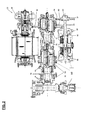
- an exemplary gearing arrangement 52 is provided and includes a hydro-mechanical transmission 54, a mechanical transmission 56 and a differential 72.
- the mechanical transmission 56 is operably coupled to the low-pressure spool 36 to be receptive of an input rotational speed of the gas turbine engine 10.
- the differential 72 is operably interposed between the mechanical transmission 56 and the generator 50.
- the mechanical transmission 56 receives a rotational input via bevel gear 74 that is reflective of the rotational speed of the low-pressure spool 36.
- the bevel gear 74 is directly coupled to carrier shaft 76.
- the carrier shaft 76 transmits the rotation to the first differential gear arrangement 68, which may be configured as a two-speed planetary gear arrangement.
- An output of the first differential gear arrangement 68 is coupled to the differential carrier shaft 70, which then transmits rotation to the second differential gear arrangement 72.
- the second differential gear arrangement 72 is rotatably coupled to the generator 50 at generator gear mesh 80.
- the mechanical transmission 56 may be configured to be selectively adjusted between at least a first position and a second position.
- the mechanical transmission 56 operates such that the input rotational speed of the carrier shaft 76 is transmitted through the first differential gear arrangement 68 and output to the differential carrier shaft 70 at twice the rotational speed of the low-pressure spool 36.
- the mechanical transmission 56 operates such that the input rotational speed of the carrier shaft 76 is transmitted through the first differential gear arrangement 68 and output to the differential carrier shaft 70 at the same rotational speed of the low-pressure spool 36.
- the mechanical transmission 56 is thus a two-speed transmission although it is to be understood that the mechanical transmission 56 may be configured as a three-speed transmission or a transmission with more than 3 speeds.
- the generator 50 may have a rated speed at which the generator 50 is to be rotatably driven such that power can be delivered to the various loads coupled to the generator 50 at the appropriate operating frequencies.
- these operating frequencies may be a relatively constant frequency or a variable frequency within a range of about 360-800 Hz and, as such, it may be necessary for the second differential gear arrangement 72 to rotatably drive the generator 50 via the generator gear mesh 80 at about 24,000 rpm, for example.
- the mechanical transmission 56 should be operated in the first position (i.e., the 1st gear) and, if the low-pressure spool 36 is operating at 4,000 rpm, the mechanical transmission 56 should be operated in the second position (i.e., the 2nd gear).
- the second differential gear arrangement 72 is rotatably coupled to the hydro-mechanical transmission 54 at variable pump gear mesh 82 and trim gear mesh 84.
- the hydro-mechanical transmission 54 includes two controllable, variable displacement pumps 90 and 96.
- variable displacement pump 96 Within the normal engine operating speed range (i.e., 2000-10000 rpm), variable displacement pump 96 has its swash plate positioned on its generate mode stop in order to provide max displacement.
- Variable displacement pump 90 has its displacement altered as necessary to maintain generator output frequency at a constant or relatively constant frequency.
- variable displacement pump 90 When mechanical transmission 56 is operating in the first position and the low-pressure spool 36 is operating below 2,000 rpm due to a throttling down or failure of the gas turbine engine 10, the swash plate angle of the variable displacement pump 90 is positioned on its max pumping stop and the swash plate of variable displacement pump 96 is controlled, reducing its displacement in order to maintain generator output frequency at a constant or relatively constant frequency. Generator power output capability during sub-normal operating input operating speeds reduces a proportional pump 96 swash plate angle.
- the hydro-mechanical transmission 54 allows the low-pressure spool 36 to be used as an emergency power source during throttling down or failure of the gas turbine engine 10, it may be possible to reduce aircraft weight and to thereby increase fuel economy, payload and/or passenger carrying capability. Moreover, the use of the hydro-mechanical transmission 54 will allow for elimination of an emergency power generator, such as a RAM air turbine, and a hydraulic pump with these features generally being relatively heavy and prone to occupying relatively large volumes considering that they are often used only for throttling down or failure scenarios.
- an emergency power generator such as a RAM air turbine
- a controller 100 may be provided and disposed in signal communication with the mechanical transmission 56 and the hydro-mechanical transmission 54. More particularly, the controller 100 may be operably coupled to the mechanical transmission 56 and to the hydro-mechanical transmission 54 and thereby configured to control the mechanical transmission 56 to operate in the first or second position and to control the respective angles of each of the variable position swash plates of pumps 96 and 90.
- the controller 100 would be able to sense a magnitude of the rotational speed of the low-pressure spool 36 and set the mechanical transmission 56 to operate in the appropriate position (i.e., 1st or 2nd gear) and make a further determination as to whether the hydro-mechanical transmission 54 is needed to step-up or step-down the speed at which the generator 50 is driven. That is, if it is found that the low-pressure spool 36 is rotating well below a minimum speed for the first gear, the angle of the variable position swash plate 96 of the hydro-mechanical transmission 54 can be changed accordingly to step-up the rotational speed.
Landscapes
- Engineering & Computer Science (AREA)
- Chemical & Material Sciences (AREA)
- Combustion & Propulsion (AREA)
- Mechanical Engineering (AREA)
- General Engineering & Computer Science (AREA)
- Control Of Turbines (AREA)
- Control Of Fluid Gearings (AREA)
Applications Claiming Priority (2)
| Application Number | Priority Date | Filing Date | Title |
|---|---|---|---|
| US13/192,526 US8561503B2 (en) | 2011-07-28 | 2011-07-28 | Motor-generator and prime mover gearing assembly |
| US13/436,278 US20130260940A1 (en) | 2012-03-30 | 2012-03-30 | Gearing Assembly |
Publications (2)
| Publication Number | Publication Date |
|---|---|
| EP2551493A2 true EP2551493A2 (de) | 2013-01-30 |
| EP2551493A3 EP2551493A3 (de) | 2016-12-07 |
Family
ID=46581814
Family Applications (1)
| Application Number | Title | Priority Date | Filing Date |
|---|---|---|---|
| EP12177304.8A Withdrawn EP2551493A3 (de) | 2011-07-28 | 2012-07-20 | Getriebeanordnung |
Country Status (1)
| Country | Link |
|---|---|
| EP (1) | EP2551493A3 (de) |
Cited By (1)
| Publication number | Priority date | Publication date | Assignee | Title |
|---|---|---|---|---|
| CN114183779A (zh) * | 2021-11-03 | 2022-03-15 | 品风燃气安全技术(广东)有限公司 | 一种自发电点火的安全燃气炉灶 |
Family Cites Families (4)
| Publication number | Priority date | Publication date | Assignee | Title |
|---|---|---|---|---|
| US3722324A (en) * | 1971-11-01 | 1973-03-27 | Sundstrand Corp | Hydromechanical transmission |
| US4713982A (en) * | 1985-12-27 | 1987-12-22 | Sundstrand Corporation | Integral gear box and electrical generating system |
| US5028803A (en) * | 1989-03-22 | 1991-07-02 | Sundstrand Corporation | Integrated drive generator system with direct motor drive prime mover starting |
| WO2008044972A1 (en) * | 2006-10-13 | 2008-04-17 | Volvo Aero Corporation | A device for retrieval of power from a gas turbine engine, and a gas turbine engine |
-
2012
- 2012-07-20 EP EP12177304.8A patent/EP2551493A3/de not_active Withdrawn
Non-Patent Citations (1)
| Title |
|---|
| None |
Cited By (1)
| Publication number | Priority date | Publication date | Assignee | Title |
|---|---|---|---|---|
| CN114183779A (zh) * | 2021-11-03 | 2022-03-15 | 品风燃气安全技术(广东)有限公司 | 一种自发电点火的安全燃气炉灶 |
Also Published As
| Publication number | Publication date |
|---|---|
| EP2551493A3 (de) | 2016-12-07 |
Similar Documents
| Publication | Publication Date | Title |
|---|---|---|
| EP2551494B1 (de) | Motor-Generator und Antriebsmaschine-Getriebebaugruppe | |
| JP5101858B2 (ja) | ガスタービンエンジンの付属機械の駆動装置 | |
| EP3517436B1 (de) | Kabinengebläsesystem | |
| US10302018B2 (en) | Gas turbine engine geared compressor with first and second input rotors | |
| CA2844186C (en) | Gas turbine engine with transmission and method of adjusting rotational speed | |
| EP3604764B1 (de) | Mehrwellengasturbinentriebwerk | |
| RU2429360C2 (ru) | Система приведения в движение вспомогательных механизмов двухступенчатого турбинного двигателя, способ функционирования системы (варианты) | |
| EP2071153B1 (de) | Gasturbine mit einem gegenläufigen Verdichter | |
| EP2859202B1 (de) | Doppelkompressoren für einen einzelturbinenantrieb | |
| EP3020953B1 (de) | Gasturbinenmotor | |
| US9353754B2 (en) | Multi-stage axial compressor with counter-rotation using accessory drive | |
| EP3626945A1 (de) | Gasturbinenmotorsystem mit variablem übersetzungsverhältnis | |
| EP2859194A1 (de) | Kombination aus zwei gasturbinen zum antrieb einer last | |
| US20130260940A1 (en) | Gearing Assembly | |
| EP2551493A2 (de) | Getriebeanordnung | |
| CN113756962A (zh) | 具有对转子不平衡的改进的响应的飞机燃气涡轮发动机 | |
| GB2478852A (en) | Drive arrangement for a turbomachine | |
| EP3482490B1 (de) | Stufenloses getriebe mit hilfsantrieb und system damit | |
| EP3734109A1 (de) | Verfahren und system zur reduzierung von querwellenschwingungen | |
| EP3628849A1 (de) | Schubausgleichssteuerung mit differentieller leistungsaufnahme | |
| US20160160761A1 (en) | Gas Turbine Engine With Single Turbine Driving Two Compressors |
Legal Events
| Date | Code | Title | Description |
|---|---|---|---|
| PUAI | Public reference made under article 153(3) epc to a published international application that has entered the european phase |
Free format text: ORIGINAL CODE: 0009012 |
|
| AK | Designated contracting states |
Kind code of ref document: A2 Designated state(s): AL AT BE BG CH CY CZ DE DK EE ES FI FR GB GR HR HU IE IS IT LI LT LU LV MC MK MT NL NO PL PT RO RS SE SI SK SM TR |
|
| AX | Request for extension of the european patent |
Extension state: BA ME |
|
| PUAL | Search report despatched |
Free format text: ORIGINAL CODE: 0009013 |
|
| AK | Designated contracting states |
Kind code of ref document: A3 Designated state(s): AL AT BE BG CH CY CZ DE DK EE ES FI FR GB GR HR HU IE IS IT LI LT LU LV MC MK MT NL NO PL PT RO RS SE SI SK SM TR |
|
| AX | Request for extension of the european patent |
Extension state: BA ME |
|
| RIC1 | Information provided on ipc code assigned before grant |
Ipc: F02C 7/36 20060101AFI20161028BHEP |
|
| STAA | Information on the status of an ep patent application or granted ep patent |
Free format text: STATUS: THE APPLICATION IS DEEMED TO BE WITHDRAWN |
|
| 18D | Application deemed to be withdrawn |
Effective date: 20170608 |