EP2551518A2 - Transformator zur Windenergieerzeugung und Windenergieerzeugungssystem - Google Patents
Transformator zur Windenergieerzeugung und Windenergieerzeugungssystem Download PDFInfo
- Publication number
- EP2551518A2 EP2551518A2 EP12177856A EP12177856A EP2551518A2 EP 2551518 A2 EP2551518 A2 EP 2551518A2 EP 12177856 A EP12177856 A EP 12177856A EP 12177856 A EP12177856 A EP 12177856A EP 2551518 A2 EP2551518 A2 EP 2551518A2
- Authority
- EP
- European Patent Office
- Prior art keywords
- transformer
- power generation
- wind power
- tower
- heat exchanger
- Prior art date
- Legal status (The legal status is an assumption and is not a legal conclusion. Google has not performed a legal analysis and makes no representation as to the accuracy of the status listed.)
- Ceased
Links
Images



Classifications
-
- H—ELECTRICITY
- H01—ELECTRIC ELEMENTS
- H01F—MAGNETS; INDUCTANCES; TRANSFORMERS; SELECTION OF MATERIALS FOR THEIR MAGNETIC PROPERTIES
- H01F27/00—Details of transformers or inductances, in general
- H01F27/08—Cooling; Ventilating
- H01F27/10—Liquid cooling
- H01F27/16—Water cooling
-
- F—MECHANICAL ENGINEERING; LIGHTING; HEATING; WEAPONS; BLASTING
- F03—MACHINES OR ENGINES FOR LIQUIDS; WIND, SPRING, OR WEIGHT MOTORS; PRODUCING MECHANICAL POWER OR A REACTIVE PROPULSIVE THRUST, NOT OTHERWISE PROVIDED FOR
- F03D—WIND MOTORS
- F03D80/00—Details, components or accessories not provided for in groups F03D1/00 - F03D17/00
- F03D80/60—Cooling or heating of wind motors
-
- H—ELECTRICITY
- H01—ELECTRIC ELEMENTS
- H01F—MAGNETS; INDUCTANCES; TRANSFORMERS; SELECTION OF MATERIALS FOR THEIR MAGNETIC PROPERTIES
- H01F27/00—Details of transformers or inductances, in general
- H01F27/02—Casings
- H01F27/025—Constructional details relating to cooling
-
- H—ELECTRICITY
- H01—ELECTRIC ELEMENTS
- H01F—MAGNETS; INDUCTANCES; TRANSFORMERS; SELECTION OF MATERIALS FOR THEIR MAGNETIC PROPERTIES
- H01F27/00—Details of transformers or inductances, in general
- H01F27/08—Cooling; Ventilating
- H01F27/10—Liquid cooling
- H01F27/12—Oil cooling
-
- Y—GENERAL TAGGING OF NEW TECHNOLOGICAL DEVELOPMENTS; GENERAL TAGGING OF CROSS-SECTIONAL TECHNOLOGIES SPANNING OVER SEVERAL SECTIONS OF THE IPC; TECHNICAL SUBJECTS COVERED BY FORMER USPC CROSS-REFERENCE ART COLLECTIONS [XRACs] AND DIGESTS
- Y02—TECHNOLOGIES OR APPLICATIONS FOR MITIGATION OR ADAPTATION AGAINST CLIMATE CHANGE
- Y02E—REDUCTION OF GREENHOUSE GAS [GHG] EMISSIONS, RELATED TO ENERGY GENERATION, TRANSMISSION OR DISTRIBUTION
- Y02E10/00—Energy generation through renewable energy sources
- Y02E10/70—Wind energy
- Y02E10/72—Wind turbines with rotation axis in wind direction
Definitions
- the present invention relates to a transformer for wind power generation or a wind power generation system and, in particular, to the cooling thereof.
- wind power generation systems In sending generated electric power to electric power systems, wind power generation systems generally raise the voltage by means of transformers.
- patent literature (PTL) 1 describes a technology in this field.
- PTL 1 describes a wind power generation facility in which an entire transformer is contained in a tower, and the transformer and the wall surfaces of the tower are components of the cooling circuit which is configured as a closed circuit.
- the transformer described in PTL 2 is a transformer for buildings which is installed on a building floor, and the transformer's main body is contained in an electrical facility room that accommodates electrical equipment, and a natural air-cooling radiator connected to the transformer's main body is installed in an exterior location of the floor.
- PTL 3 describes the situation in which a liquid refrigerant for cooling the transformer structure located in a tank is cooled by cooling water from a cooler located outside the tank, and the cooling water is recooled in the cooling tower.
- air for cooling the insulating cooling medium itself, such as oil, which has taken heat from the transformer's main body circulates through the cooling circuit which is configured as a closed circuit that includes the wall surfaces of the tower.
- a cooling medium, such as oil is cooled by air (that circulates throughout the tower's interior), and the ability to cool the cooling medium, such as oil, which has large thermal capacity and large thermal conductivity is limited.
- a transformer's main body is encased in the building's electrical facility room, and the transformer's radiator is installed outside the building. Accordingly, most of the heat emitted from the transformer's main body is directly discharged to the outside air via a radiator, and therefore, temperature of the electrical facility room where the transformer's main body is located does not increase much.
- a cooling medium such as oil
- the ability to cool the cooling medium, such as oil, which has large thermal capacity and large thermal conductivity is limited.
- an objective of the present invention is to provide a transformer capable of easily increasing cooling performance and provide a wind power generation system equipped with the transformer.
- a transformer for wind power generation is configured such that the transformer's main body, which contains an insulating refrigerant in a tank where an iron core and windings mounted to the iron core are contained, is disposed in a tower which configures a wind power generation system, and the transformer for wind power generation uses water surrounding the wind power generation system as a secondary refrigerant for cooling the aforementioned refrigerant.
- the present invention it is possible to provide a transformer for wind power generation capable of easily increasing cooling performance and provide a wind power generation system equipped with the transformer.
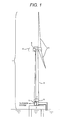
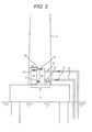
- Example 1 will be described with reference to FIG. 1 and FIG. 2 .
- a wind power generation system 1 in this example roughly comprises a tower (support column) 3 which is built on an offshore base 2, a nacelle 4 that is disposed on the top of the tower 3 and supported by the tower 3 as a support shaft so that it can rotate within a surface vertical to the shaft of the tower, a rotor blade 5 that is installed at the tip of the nacelle 4 and rotates by wind, and a power generator 6 connected to the rotor blade 5.
- a transformer 7 in this example is roughly composed of the transformer's main body (the main body of the transformer) 8 and a water-cooled heat exchanger 9, both of which are contained in the tower 3 of the wind power generation system 1.
- the transformer 7 for wind power generation comprises the transformer's main body 8, a water-cooled heat exchanger 9, an upper pipe 10 and a lower pipe 11 that connect the transformer's main body 8 and the water-cooled heat exchanger 9 to enable a cooling medium 16 to move therebetween, an upper water pipe 12 that serves as a channel for discharging water from the water-cooled heat exchanger 9, a lower water pipe 13 that serves as a channel for supplying water to the water-cooled heat exchanger 9, and a water pump 14 that is provided with the lower water pipe 13 so as to supply water to the water-cooled heat exchanger 9, wherein the upper water pipe 12 and the lower water pipe 13 extend into the sea so as to use seawater as circulating water.
- the aforementioned transformer's main body 8 is configured such that an insulating cooling medium 16, such as mineral oil, is contained in the transformer's tank (a tank for the transformer) 15, which is an airtight container for containing an iron core and exciting windings mounted to the iron core.
- an insulating cooling medium 16 such as mineral oil
- the interior of the water-cooled heat exchanger 9 is constructed such that the cooling medium 16 having high temperature (as the result of taking heat from the transformer's main body 8) and low-temperature seawater 17 for cooling the medium flow alongside to each other with a solid wall interposed to avoid the two liquids from mixing, wherein heat transfers from the high-temperature cooling medium 16 to the low-temperature seawater 17, which is a secondary refrigerant, thereby decreasing the temperature of the cooling medium 16 and increasing the temperature of the seawater 17.
- the water-cooled heat exchanger 9 uses a shell and tube heat exchanger in which a large number of tubes are supported in parallel and contained in a cylindrical shell, and different fluids flow inside and outside the tubes; alternatively, the water-cooled heat exchanger 9 uses a plate-type heat exchanger in which a channel is created by placing a large number of plates so that a high-temperature fluid and a low-temperature fluid alternately flow on both sides of the plates.
- seawater 17 as cooling water for the water-cooled heat exchanger 9 as in this example
- seawater since seawater has very high salt content as well as a large number of impurities and diverse organisms, it is necessary to prevent material strength from decreasing due to corrosion as well as heat transfer performance from deteriorating due to contamination of the heat transfer surface.
- the corrosion of material With regard to the corrosion of material, it is possible to increase corrosion resistance by using stainless steel material.
- contamination of the heat transfer surface mainly results from sea life attaching to and reproducing on the heat transfer surface.
- the cooling medium 16 in the transformer's tank 15 raises its temperature as the result of taking heat generated in the iron core and the windings, thereby increasing its volume and decreasing its density.
- the high-temperature cooling medium 16 having low density and relatively light weight ascends and flows into the upper part of the water-cooled heat exchanger 9 through the upper pipe 10 disposed on the upper side.
- the cooling medium 16 that has flown into the heat exchanger 9 exchanges heat with the low-temperature seawater 17 that flows through the channel divided by the solid wall in the heat exchanger 9.
- the cooling medium 16 from which heat has been taken by the low-temperature seawater 17 lowers its temperature, and the reduced volume increases density and weight relatively; thus, the cooling medium 16 descends in the heat exchanger 9.
- the cooling medium 16 returns to the transformer's tank 15 through the lower pipe 11 provided on the lower side and contributes to the cooling of the transformer's tank 15. That is, natural convection occurs with the increase and decrease of temperature, which makes the cooling medium 16 circulate.
- Seawater 17 serves as a secondary refrigerant in such a way that seawater is pumped from the sea by a water pump 14 and flows through the lower water pipe 13 to the water-cooled heat exchanger 9, where the seawater takes heat from the high-temperature cooling medium 16, becomes hot, and is then discharged to the sea through the upper water pipe 12.
- a heat exchanger 9 is used that cools the medium by use of seawater 17 having high cooling characteristics instead of using a radiator that cools the medium by air having low cooling characteristics.
- thermal capacity increases even if the volume is the same. Therefore, when compared with the situation where a radiator is used, it is possible to reduce the size of the water-cooled heat exchanger 9.
- the tower 3 When used in an offshore wind power generation system 1, the tower 3 is required to have a small installation area. Thus, a small-size transformer 7 is preferred when it is contained in the tower 3.
- seawater 17 since the volume of seawater is enormous, the temperature of seawater of the entire sea does not change even if seawater 17 that has had its temperature raised as the result of taking heat from the cooling medium 16 is discharged to the sea. Accordingly, low-temperature seawater 17 can always be supplied by a pump 14 to the water-cooled heat exchanger 9. Consequently, for example, it is not necessary to provide a cooling tower or the like to lower the water temperature, and cooling performance can be increased by means of a simple configuration.
- Example 2 a cooling medium 16 that has had its temperature raised as the result of taking heat from the transformer's main body 8 is cooled by seawater 17 by means of a simpler configuration without using a water-cooled heat exchanger 9.
- a spiral corrugated tube (not illustrated) is vertically disposed along the inner wall of the upper part of the transformer's tank 15; and the both ends (inlet and outlet) of the corrugated tube are connected to the upper water pipe 12 and the lower water pipe 13. Then, a water pump 14 is installed in the middle of the lower water pipe 13.
- Other portions are the same as those of Example 1 and repeated explanations will be omitted.
- the cooling medium 16 in the transformer's tank 15 raises its temperature as the result of taking heat generated in the iron core and the windings, and with the increase in temperature, the volume increases and the density decreases relatively.
- the high-temperature cooling medium 16 having low density and light weight ascends toward the upper part of the transformer's tank 15 in which the corrugated tube is disposed. Since low-temperature seawater 17 provided through the lower water pipe 13 by a water pump 14 flows through the corrugated tube, the low-temperature seawater 17 and the high-temperature cooling medium 16 exchange heat via the corrugated tube.
- the high-temperature cooling medium 16 that has ascended to the upper part of the transformer's tank 15 is cooled, lowers its temperature, and decreases its volume relatively. Consequently, its density increases, which generates natural convection that moves downward along the inner wall of the transformer's tank 15. In such a way, a circulating flow of the cooling medium 16 is generated in the transformer's tank 15.
- Seawater 17 which serves as a secondary refrigerant, is pumped from the sea by the water pump 14 and flows through the lower water pipe 13 to the corrugated tube located on the upper part of the transformer's tank 15, where the seawater takes heat from the high-temperature cooling medium 16 surrounding the corrugated tube, becoming hot, and is then discharged to the sea through the upper water pipe 12.
- Example 2 when compared with Example 1, a water-cooled heat exchanger 9, an upper pipe 10, and a lower pipe 11 are eliminated, which can further reduce the size of the equipment and simplify the entire configuration.
- This configuration can reduce costs and prevent air temperature in the tower 3 of the wind power generation system 1 from increasing similar to Example 1. Accordingly, it is also possible to significantly reduce the size of the ventilation and air conditioning equipment of the tower 3 or eliminate it altogether.
- the tower 3 when used in an offshore wind power generation system 1, the tower 3 is required to have a small installation area. Thus, it is obvious that a smaller transformer 7 than that of Example 1 is more preferred when it is contained in the tower 3.
- the corrugated tube is installed in the upper part of the transformer's tank 15, it is obvious that the corrugated tube may be disposed vertically throughout the interior of the transformer's tank 15.
- the corrugated tube is disposed in a centralized manner on the upper part of the transformer's tank 15 as described in detail in this example, heat can be intensively exchanged with the high-temperature cooling medium.
- the cooling effects per unit surface area of the corrugated tube are increased.
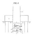
- Example 3 will be described with reference to FIG. 4 . However, with regard to a portion that is the same as the aforementioned portion, repeated explanations will be omitted.
- configuration is different from Example 1 in two points: one point is that the tower 3 is extended downward below the base 2 so that the lower part of the tower 3 is located under water and the transformer 7 (i.e., the transformer's main body 8 and the heat exchanger 9) is installed in the submerged portion of the tower 3; and the other point is that no water pump is provided for supplying and discharging seawater 17 to and from the water-cooled heat exchanger 9.
- the transformer 7 i.e., the transformer's main body 8 and the heat exchanger 9
- the cooling medium 16 behaves in the same manner as Example 1.
- the water-cooled heat exchanger 9, the upper water pipe 12, and the lower water pipe 13 are all located below the sea level. That is, seawater 17 flows through the lower water pipe 13 to the heat exchanger 9 without using a water pump.
- the flowing seawater 17 raises its temperature as the result of taking heat from the high-temperature cooling medium 16, which increases the volume and relatively decreases the density.
- the seawater 17 having low density and relatively light weight flows upward in the heat exchanger 9 and is discharged to the sea through the upper water pipe 12. That is, even without a water pump, the seawater 17 can flow in the heat exchanger 9 according to natural convection.
- Example 2 when compared with Example 1, a water pump is unnecessary. Since a water pump is not provided, the size of the equipment can be reduced and the configuration itself can be simplified, reducing the costs. Furthermore, since the lower part of the tower 3 of the offshore wind power generation system 1 is located under water, the wall surfaces of the tower are cooled by seawater having better cooling characteristics than those of the air. Thus, temperature of air in the tower 3 decreases more significantly than in the case of Example 1. Accordingly, it is possible to significantly reduce the size of the ventilation and air conditioning equipment of the tower 3 or eliminate it altogether, and synergistic effects can be expected.
- Example 3 it is also possible to apply the configuration of Example 3 to Example 2 in which a spiral corrugated tube is disposed along the inner wall of the upper part of the transformer's tank 15, and both ends of the corrugated tube are connected to the upper water pipe 12 and the lower water pipe 13. That is, by extending the tower 3 downward below the base 2 so that the lower part of the tower 3 is located under water and the transformer 7 is installed in the submerged portion of the tower, it is obvious that the same effects as those of example 3, as described above, can be obtained in addition to the effects of Example 2 described above.
- Example 4 will be described with reference to FIG. 5 . However, with regard to a portion that is the same as the aforementioned portion, repeated explanations will be omitted.
- configuration is different from Example 3 in two points: one point is that the water-cooled radiator 18 connected to the tank 15 of the transformer's main body 8 by means of the upper pipe 10 and the lower pipe 11 is located outside the tower 3; and the other point is that the water-cooled radiator 18 is not equipped with an upper water pipe 12 and a lower water pipe 13 for circulating seawater.
- the water-cooled radiator 18 is composed of a plurality of radiating panels (not illustrated) through which a cooling medium 16 flows. A large number of radiating panels are disposed vertically to the upper and lower pipes 10 and 11 in the direction of the axis of the pipes 10 and 11.
- the cooling medium 16 in the transformer's tank 15 raises its temperature as the result of taking heat generated in the iron core and the windings, which increases its volume and relatively decreases its density.
- the cooling medium 16 having low density and relatively light weight flows through the upper pipe 10 into the upper part of the water-cooled radiator 18 installed outside the tower 3.
- the cooling medium 16 that has flown into the radiator 18 is cooled via radiating panels by seawater 17 located outside the radiator 18 according to natural convection of seawater; and the heat is transferred to the seawater 17.
- the cooling medium 16 lowers its temperature and increases its density. Then, the cooling medium 16 flows downward in the radiators 18 and is returned to the transformer's tank 15 through the lower pipe 11.
- Example 3 the heat generated in the transformer's main body 8 is directly transferred to the seawater 17 from the cooling medium 16 that flows through the water-cooled radiator 18; and the temperature of air inside the tower 3 of the offshore wind power generation system 1 that contains the transformer's main body 8 is almost the same as that of Example 3. Accordingly, it is possible to significantly reduce the size of the ventilation and air-conditioning equipment of the tower 3 or eliminate it altogether. Furthermore, when compared with Example 3, the upper water pipe and the lower water pipe are not necessary, which reduces the number of parts. Therefore, configuration becomes simple and overall costs can be reduced. Since a water pump is not provided, there is no possibility of a failure of a water pump causing a water-cooled radiator 18 to stop operating, and reliability can be increased as in Example 3.
- Example 5 will be described with reference to FIG. 6 . However, with regard to a portion that is the same as the aforementioned portion, repeated explanations will be omitted.
- the transformer's main body 8 is contained in the tower 3 of the wind power generation system 1, and a part of the outer wall of the tower 3 is configured as a double structure where a vertically conducting channel 19 is created.
- the channel 19 and the tank 15 of the transformer's main body 8 are connected by means of the upper pipe 10 and the lower pipe 11. Outside of the double-structure portion where the channel 19 has been created is covered with seawater.
- the cooling medium 16 in the transformer's tank 15 raises its temperature as the result of taking heat generated in the iron core and the windings, which increases its volume relatively and decreases its density.
- the cooling medium 16 having low density and light weight ascends and flows through the upper pipe 10 into the upper part of the channel 19 located in the double-structure portion formed in the outer wall of the tower 3. Outside the channel 19 formed in the double structure, low-temperature seawater surrounds the tower 3, and the cooling medium 16 exchange heat with seawater via the outer wall of the tower 3.
- the cooling medium 16 lowers its temperature, reduces its volume, and increases its density; the cooling medium 16 then flows downward through the channel 19 in the double-structure portion and returns to the transformer's tank 15 through the lower pipe 11; thus, a flow is created.
- the outer wall of the tower 3 of the offshore wind power generation system 1 comes in contact with seawater having superior cooling characteristics, it is possible to obtain high cooling performance. Accordingly, it is possible to eliminate a water-cooled radiator for discharging heat generated in the transformer's main body 8 to seawater, which reduces the number of devices and simplifies the configuration, reducing the costs.
- the wind power generation system can be a land wind power generation system located by the sea that can use seawater.
- a wind power generation system is located in the environment surrounded by large-capacity of natural water, such as a lake, pond, or river, installation is possible by properly modifying the configuration, regardless of on water or on land.
- the transformer according to the present invention most of the heat from the transformer's main body is directly discharged to the surrounding environment such as seawater. Therefore, it is possible to significantly reduce the size of the ventilation and air-conditioning equipment that needs to be disposed in the conventional tower or eliminate it altogether. Furthermore, since temperature of a large-capacity water source such as seawater does not change, it is not necessary to provide a cooling tower for lowering the water temperature, which simplifies the configuration and reduces the costs. Thus, industrial applicability of the present invention is high.
- the present invention is not limited to the aforementioned examples and includes a variety of modifications.
- the aforementioned examples have been described in detail for better understanding of the present invention, and the present invention is not limited to those provided with all of the described configurations.
- addition of configuration of other examples, deletion, or replacement may be made.
Landscapes
- Engineering & Computer Science (AREA)
- Power Engineering (AREA)
- Physics & Mathematics (AREA)
- Thermal Sciences (AREA)
- Life Sciences & Earth Sciences (AREA)
- Sustainable Development (AREA)
- Sustainable Energy (AREA)
- Chemical & Material Sciences (AREA)
- Combustion & Propulsion (AREA)
- Mechanical Engineering (AREA)
- General Engineering & Computer Science (AREA)
- Wind Motors (AREA)
Applications Claiming Priority (1)
| Application Number | Priority Date | Filing Date | Title |
|---|---|---|---|
| JP2011161541A JP5492832B2 (ja) | 2011-07-25 | 2011-07-25 | 変圧器及び風力発電システム |
Publications (2)
| Publication Number | Publication Date |
|---|---|
| EP2551518A2 true EP2551518A2 (de) | 2013-01-30 |
| EP2551518A3 EP2551518A3 (de) | 2017-06-21 |
Family
ID=46551442
Family Applications (1)
| Application Number | Title | Priority Date | Filing Date |
|---|---|---|---|
| EP12177856.7A Ceased EP2551518A3 (de) | 2011-07-25 | 2012-07-25 | Transformator zur Windenergieerzeugung und Windenergieerzeugungssystem |
Country Status (4)
| Country | Link |
|---|---|
| US (1) | US20130026764A1 (de) |
| EP (1) | EP2551518A3 (de) |
| JP (1) | JP5492832B2 (de) |
| CN (1) | CN102903484B (de) |
Cited By (2)
| Publication number | Priority date | Publication date | Assignee | Title |
|---|---|---|---|---|
| EP2444768A1 (de) * | 2010-10-22 | 2012-04-25 | Tai-Her Yang | Elektrisches Gerät mit Wärmeabfuhr durch Flüssigkeitskreislauf und externem Wärmeaustausch |
| DE102016200800A1 (de) * | 2016-01-21 | 2017-07-27 | Siemens Aktiengesellschaft | Offshorebauwerk |
Families Citing this family (14)
| Publication number | Priority date | Publication date | Assignee | Title |
|---|---|---|---|---|
| JP5992176B2 (ja) * | 2012-02-10 | 2016-09-14 | エムエイチアイ ヴェスタス オフショア ウィンド エー/エス | 風力発電装置 |
| NZ712104A (en) * | 2013-03-14 | 2017-07-28 | Arranged Bvba | Pressure vessel based tower structure |
| JP2015031233A (ja) * | 2013-08-06 | 2015-02-16 | 株式会社日立産機システム | 風力発電システム及びその変圧器搬入、搬出方法 |
| CN105899806B (zh) * | 2013-09-20 | 2018-11-27 | 株式会社日立产机系统 | 海上风力发电装置及其使用的油浸式变压器 |
| US10348172B2 (en) | 2013-11-13 | 2019-07-09 | Brooks Automation, Inc. | Sealed switched reluctance motor |
| KR20230116962A (ko) | 2013-11-13 | 2023-08-04 | 브룩스 오토메이션 인코퍼레이티드 | 브러쉬리스 전기 기계 제어 방법 및 장치 |
| WO2015073647A1 (en) | 2013-11-13 | 2015-05-21 | Brooks Automation, Inc. | Sealed robot drive |
| TWI695447B (zh) | 2013-11-13 | 2020-06-01 | 布魯克斯自動機械公司 | 運送設備 |
| DE102015122855A1 (de) * | 2015-12-28 | 2017-06-29 | Wobben Properties Gmbh | Windenergieanlage und Kühlvorrichtung für eine Windenergieanlage |
| CN108417356A (zh) * | 2018-04-12 | 2018-08-17 | 广东瑞智电力科技有限公司 | 一种海上风电升压系统的植物油变压器 |
| CN111918522A (zh) * | 2020-06-19 | 2020-11-10 | 南方电网科学研究院有限责任公司 | 一种换流站冷却系统 |
| CN111692051B (zh) * | 2020-07-17 | 2024-09-20 | 中船海装风电有限公司 | 一种浮式风力发电机组的冷却和通风换气系统 |
| EP4123168B1 (de) * | 2021-07-19 | 2025-12-31 | Siemens Gamesa Renewable Energy A/S | Offshore-windturbine mit einer flüssigkeitszufuhranordnung |
| CN114962138A (zh) * | 2022-06-24 | 2022-08-30 | 莫一凡 | 水面漂浮清洁能源发电储能装置 |
Citations (3)
| Publication number | Priority date | Publication date | Assignee | Title |
|---|---|---|---|---|
| JPS63213330A (ja) | 1987-02-27 | 1988-09-06 | Takenaka Komuten Co Ltd | ビル用変圧器 |
| JPH02206104A (ja) | 1989-02-06 | 1990-08-15 | Hitachi Ltd | 変圧器 |
| WO2001006121A1 (de) | 1999-07-14 | 2001-01-25 | Aloys Wobben | Windenergieanlage mit einem geschlossenen kühlkreislauf |
Family Cites Families (22)
| Publication number | Priority date | Publication date | Assignee | Title |
|---|---|---|---|---|
| GB554217A (en) * | 1941-10-31 | 1943-06-24 | Asea Ab | Cooling arrangement for transformers, condensers and other electrical apparatus |
| US3028566A (en) * | 1958-10-08 | 1962-04-03 | Gen Electric | Cooling system for electrical induction apparatus |
| US4394635A (en) * | 1981-04-16 | 1983-07-19 | General Electric Company | Method for determining dissolved gas concentrations in dielectric coolants |
| JPS5864011A (ja) * | 1981-10-13 | 1983-04-16 | Toshiba Corp | 水力発電所用変圧器の冷却装置 |
| DE10016913A1 (de) * | 2000-04-05 | 2001-10-18 | Aerodyn Eng Gmbh | Offshore-Windenergieanlage mit einem Wärmetauschersystem |
| DE10324228B4 (de) * | 2003-05-28 | 2006-02-16 | Rittal Gmbh & Co. Kg | Kühlvorrichtung für eine Offshore-Windenergieanlage |
| CN101006532A (zh) * | 2004-06-18 | 2007-07-25 | 西门子公司 | 用于冷却风力发电设备的部件的装置 |
| DE102004063508B4 (de) * | 2004-12-27 | 2008-10-16 | Siemens Ag | Elektrisches Bauteil mit Kühlkreislauf für den Unterwasserbetrieb |
| US7168251B1 (en) * | 2005-12-14 | 2007-01-30 | General Electric Company | Wind energy turbine |
| PL2002120T3 (pl) * | 2006-03-25 | 2010-04-30 | Clipper Windpower Inc | System obsługi ciepła w turbinie wiatrowej |
| JP2008038764A (ja) * | 2006-08-07 | 2008-02-21 | Shimadzu Corp | ターボ分子ポンプおよびそのための電源装置 |
| US8257019B2 (en) * | 2006-12-21 | 2012-09-04 | Green Energy Technologies, Llc | Shrouded wind turbine system with yaw control |
| BRPI0816417A2 (pt) * | 2007-09-20 | 2015-03-03 | Dehlsen Associates L L C | Bomba de fluido de energia renovável para geração de energia baseada em fluido |
| JP2009138555A (ja) * | 2007-12-04 | 2009-06-25 | Mitsubishi Heavy Ind Ltd | 風力発電装置 |
| JP2009250214A (ja) * | 2008-04-10 | 2009-10-29 | Mitsubishi Heavy Ind Ltd | 風力発電装置用ファン装置および風力発電装置 |
| US8439250B2 (en) * | 2009-07-01 | 2013-05-14 | Lockheed Martin Corporation | Friction-stir weld-tool and method |
| US8461953B1 (en) * | 2009-08-18 | 2013-06-11 | Marvin W. Ward | System, method and apparatus for transformer cooling |
| DE102009051215A1 (de) * | 2009-10-29 | 2011-05-12 | Li-Tec Battery Gmbh | Windkraftanlage mit Batterieanordnung |
| DE102009055784A1 (de) * | 2009-11-25 | 2011-05-26 | Siemens Aktiengesellschaft | Windkraftanlage und Verfahren zur Temperaturregulierung mindestens einer Komponente einer Windkraftanlage |
| JP5318740B2 (ja) * | 2009-12-11 | 2013-10-16 | 株式会社日立製作所 | 洋上風車 |
| CN201714586U (zh) * | 2010-07-20 | 2011-01-19 | 中船重工(重庆)海装风电设备有限公司 | 海上风力发电系统 |
| JP2012102692A (ja) * | 2010-11-12 | 2012-05-31 | Hitachi Industrial Equipment Systems Co Ltd | 風力発電用変圧器及び風力発電用変圧器を搭載する風力発電設備 |
-
2011
- 2011-07-25 JP JP2011161541A patent/JP5492832B2/ja active Active
-
2012
- 2012-07-13 CN CN201210244180.9A patent/CN102903484B/zh not_active Expired - Fee Related
- 2012-07-25 US US13/557,800 patent/US20130026764A1/en not_active Abandoned
- 2012-07-25 EP EP12177856.7A patent/EP2551518A3/de not_active Ceased
Patent Citations (4)
| Publication number | Priority date | Publication date | Assignee | Title |
|---|---|---|---|---|
| JPS63213330A (ja) | 1987-02-27 | 1988-09-06 | Takenaka Komuten Co Ltd | ビル用変圧器 |
| JPH02206104A (ja) | 1989-02-06 | 1990-08-15 | Hitachi Ltd | 変圧器 |
| WO2001006121A1 (de) | 1999-07-14 | 2001-01-25 | Aloys Wobben | Windenergieanlage mit einem geschlossenen kühlkreislauf |
| JP3715238B2 (ja) | 1999-07-14 | 2005-11-09 | アロイス・ヴォベン | 閉冷却回路を有する風力利用設備 |
Cited By (3)
| Publication number | Priority date | Publication date | Assignee | Title |
|---|---|---|---|---|
| EP2444768A1 (de) * | 2010-10-22 | 2012-04-25 | Tai-Her Yang | Elektrisches Gerät mit Wärmeabfuhr durch Flüssigkeitskreislauf und externem Wärmeaustausch |
| DE102016200800A1 (de) * | 2016-01-21 | 2017-07-27 | Siemens Aktiengesellschaft | Offshorebauwerk |
| DE102016200800B4 (de) * | 2016-01-21 | 2017-08-17 | Siemens Aktiengesellschaft | Offshorebauwerk |
Also Published As
| Publication number | Publication date |
|---|---|
| US20130026764A1 (en) | 2013-01-31 |
| CN102903484A (zh) | 2013-01-30 |
| JP5492832B2 (ja) | 2014-05-14 |
| EP2551518A3 (de) | 2017-06-21 |
| CN102903484B (zh) | 2016-01-20 |
| JP2013024177A (ja) | 2013-02-04 |
Similar Documents
| Publication | Publication Date | Title |
|---|---|---|
| EP2551518A2 (de) | Transformator zur Windenergieerzeugung und Windenergieerzeugungssystem | |
| ES2231183T3 (es) | Turbina eolica marina con refrigeracion por liquido. | |
| RU2573694C1 (ru) | Движительный агрегат корабля | |
| EP2825008B1 (de) | Ölkühlungskonfiguration für Unterwasserumwandler | |
| BRPI0811221B1 (pt) | sistema de compressor para uso subaquático na área offshore | |
| JP2015016857A (ja) | 船の推進ユニット | |
| CN216820438U (zh) | 冷却系统及数据中心 | |
| CN115163411B (zh) | 一种海上风电与数据中心集成结构 | |
| ES3042839T3 (en) | Offshore electrolysis plant and method for operating an offshore electrolysis plant | |
| CN101692384B (zh) | 强迫油循环水冷散热器 | |
| JP5992176B2 (ja) | 風力発電装置 | |
| TW201512530A (zh) | 風力發電系統及其變壓器搬入、搬出方法 | |
| CN219918586U (zh) | 驱动装置的冷却系统及飞行器 | |
| EP4450805A1 (de) | Windenergieanlage mit zumindest einem teil eines wasserstofferzeugungssystems | |
| AU2011320032B2 (en) | Heating apparatus | |
| JP2011112339A (ja) | 給湯装置 | |
| CN118281405A (zh) | 一种水下储能装置 | |
| JP2013130332A (ja) | 気泡駆動冷却装置 | |
| CN114999783A (zh) | 一种基于5g通信的电力工业监控系统 | |
| CN221574894U (zh) | 热管理系统及站房式储能电站 | |
| CN222190818U (zh) | 供液模块和电池系统 | |
| CN107369479B (zh) | 用于一体化堆的基于压差的非能动停堆系统及核反应堆 | |
| CN220357917U (zh) | 一种风力发电变压器的油箱结构 | |
| CN223515216U (zh) | 蒸发冷却系统及电力设备 | |
| CN218769010U (zh) | 一种适用于低温环境的变压器结构 |
Legal Events
| Date | Code | Title | Description |
|---|---|---|---|
| PUAI | Public reference made under article 153(3) epc to a published international application that has entered the european phase |
Free format text: ORIGINAL CODE: 0009012 |
|
| 17P | Request for examination filed |
Effective date: 20121019 |
|
| AK | Designated contracting states |
Kind code of ref document: A2 Designated state(s): AL AT BE BG CH CY CZ DE DK EE ES FI FR GB GR HR HU IE IS IT LI LT LU LV MC MK MT NL NO PL PT RO RS SE SI SK SM TR |
|
| AX | Request for extension of the european patent |
Extension state: BA ME |
|
| PUAL | Search report despatched |
Free format text: ORIGINAL CODE: 0009013 |
|
| AK | Designated contracting states |
Kind code of ref document: A3 Designated state(s): AL AT BE BG CH CY CZ DE DK EE ES FI FR GB GR HR HU IE IS IT LI LT LU LV MC MK MT NL NO PL PT RO RS SE SI SK SM TR |
|
| AX | Request for extension of the european patent |
Extension state: BA ME |
|
| RIC1 | Information provided on ipc code assigned before grant |
Ipc: H01F 27/12 20060101ALI20170516BHEP Ipc: H01F 27/02 20060101AFI20170516BHEP Ipc: H01F 27/16 20060101ALI20170516BHEP |
|
| STAA | Information on the status of an ep patent application or granted ep patent |
Free format text: STATUS: EXAMINATION IS IN PROGRESS |
|
| 17Q | First examination report despatched |
Effective date: 20190925 |
|
| STAA | Information on the status of an ep patent application or granted ep patent |
Free format text: STATUS: THE APPLICATION HAS BEEN REFUSED |
|
| 18R | Application refused |
Effective date: 20210705 |