EP2552010B1 - Machine de moulage à injection - Google Patents
Machine de moulage à injection Download PDFInfo
- Publication number
- EP2552010B1 EP2552010B1 EP12005451.5A EP12005451A EP2552010B1 EP 2552010 B1 EP2552010 B1 EP 2552010B1 EP 12005451 A EP12005451 A EP 12005451A EP 2552010 B1 EP2552010 B1 EP 2552010B1
- Authority
- EP
- European Patent Office
- Prior art keywords
- electric power
- converting
- driver circuit
- motor
- alternating
- Prior art date
- Legal status (The legal status is an assumption and is not a legal conclusion. Google has not performed a legal analysis and makes no representation as to the accuracy of the status listed.)
- Active
Links
Images



Classifications
-
- H—ELECTRICITY
- H02—GENERATION; CONVERSION OR DISTRIBUTION OF ELECTRIC POWER
- H02P—CONTROL OR REGULATION OF ELECTRIC MOTORS, ELECTRIC GENERATORS OR DYNAMO-ELECTRIC CONVERTERS; CONTROLLING TRANSFORMERS, REACTORS OR CHOKE COILS
- H02P6/00—Arrangements for controlling synchronous motors or other dynamo-electric motors using electronic commutation dependent on the rotor position; Electronic commutators therefor
-
- B—PERFORMING OPERATIONS; TRANSPORTING
- B29—WORKING OF PLASTICS; WORKING OF SUBSTANCES IN A PLASTIC STATE IN GENERAL
- B29C—SHAPING OR JOINING OF PLASTICS; SHAPING OF MATERIAL IN A PLASTIC STATE, NOT OTHERWISE PROVIDED FOR; AFTER-TREATMENT OF THE SHAPED PRODUCTS, e.g. REPAIRING
- B29C45/00—Injection moulding, i.e. forcing the required volume of moulding material through a nozzle into a closed mould; Apparatus therefor
- B29C45/17—Component parts, details or accessories; Auxiliary operations
- B29C45/76—Measuring, controlling or regulating
- B29C45/7666—Measuring, controlling or regulating of power or energy, e.g. integral function of force
-
- B—PERFORMING OPERATIONS; TRANSPORTING
- B29—WORKING OF PLASTICS; WORKING OF SUBSTANCES IN A PLASTIC STATE IN GENERAL
- B29C—SHAPING OR JOINING OF PLASTICS; SHAPING OF MATERIAL IN A PLASTIC STATE, NOT OTHERWISE PROVIDED FOR; AFTER-TREATMENT OF THE SHAPED PRODUCTS, e.g. REPAIRING
- B29C45/00—Injection moulding, i.e. forcing the required volume of moulding material through a nozzle into a closed mould; Apparatus therefor
- B29C45/17—Component parts, details or accessories; Auxiliary operations
- B29C2045/1784—Component parts, details or accessories not otherwise provided for; Auxiliary operations not otherwise provided for
- B29C2045/1792—Machine parts driven by an electric motor, e.g. electric servomotor
-
- B—PERFORMING OPERATIONS; TRANSPORTING
- B29—WORKING OF PLASTICS; WORKING OF SUBSTANCES IN A PLASTIC STATE IN GENERAL
- B29C—SHAPING OR JOINING OF PLASTICS; SHAPING OF MATERIAL IN A PLASTIC STATE, NOT OTHERWISE PROVIDED FOR; AFTER-TREATMENT OF THE SHAPED PRODUCTS, e.g. REPAIRING
- B29C45/00—Injection moulding, i.e. forcing the required volume of moulding material through a nozzle into a closed mould; Apparatus therefor
- B29C45/17—Component parts, details or accessories; Auxiliary operations
- B29C45/76—Measuring, controlling or regulating
- B29C45/7666—Measuring, controlling or regulating of power or energy, e.g. integral function of force
- B29C2045/7673—Recovering energy or power from drive motors
-
- Y—GENERAL TAGGING OF NEW TECHNOLOGICAL DEVELOPMENTS; GENERAL TAGGING OF CROSS-SECTIONAL TECHNOLOGIES SPANNING OVER SEVERAL SECTIONS OF THE IPC; TECHNICAL SUBJECTS COVERED BY FORMER USPC CROSS-REFERENCE ART COLLECTIONS [XRACs] AND DIGESTS
- Y02—TECHNOLOGIES OR APPLICATIONS FOR MITIGATION OR ADAPTATION AGAINST CLIMATE CHANGE
- Y02P—CLIMATE CHANGE MITIGATION TECHNOLOGIES IN THE PRODUCTION OR PROCESSING OF GOODS
- Y02P70/00—Climate change mitigation technologies in the production process for final industrial or consumer products
- Y02P70/10—Greenhouse gas [GHG] capture, material saving, heat recovery or other energy efficient measures, e.g. motor control, characterised by manufacturing processes, e.g. for rolling metal or metal working
Definitions
- the present invention relates to an injection molding machine which includes a motor, a driver circuit that drives the motor; and a rectifying part that supplies electric power to the driver circuit.
- JP 2006-54947 A discloses a converter which performs regeneration to a power supply when a voltage across a DC link exceeds a predetermined upper limit voltage.
- US 6,340,439 A discloses a motor-driven injection molding machine comprising an injection device which includes a heating cylinder for heating resin powder therein to melt the resin powder into molten resin and a screw disposed in the heading cylinder for feeding the molten resin in the heating cylinder forward to meter the molten resin.
- a controller positions, in response to a position detected signal detected by a position detector, the screw at a metering position using an injection servomotor on and immediately after completion of the plasticization and metering process.
- the controller rotates, in response to a pressure detected signal detected by a load cell, the screw in the opposite direction using a screw-rotation servomotor on and immediately after the completion of said plasticization and metering process to carry out depressurization of the molten resin in the heating cylinder that is metered ahead of the screw.
- JP 2006-54947 A powering electric power and regenerative electric power pass through the same A/C converter circuit, and thus the regenerative electric power generated at the time of decelerating the motor can not regenerated effectively.
- an object of the invention is to provide an injection molding machine which can effectively regenerate the regenerative electric power of the motor.
- the regenerative electric power of the motor can be effectively regenerated.
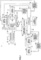
- FIG. 1 is a diagram for illustrating a configuration of an injection molding machine 1 according an embodiment of the present invention.
- the injection molding machine 1 which is a motor-operated injection molding machine in the illustrated example, includes a servo motor for injection 11.
- the rotation of the servo motor for injection 11 is transmitted to a ball screw 12.
- a nut 13 which is moved in the forward and backward directions by the rotation of the ball screw 12, is fixed to a pressure plate 14.
- the pressure plate 14 is configured to be movable along guide bars 15 and 16 which are fixed to a base frame (not illustrated).
- the motion of the pressure plate 14 in forward and backward directions is transmitted to a screw 20 via a bearing 17, a load cell 18 and an injection shaft 19.
- the screw 20 is disposed in a heating cylinder 21 in such a manner that it can rotate in the heating cylinder 21 and can move in an axial direction.
- a hopper 22 for supplying a resin is provided in a rear portion in the heating cylinder 21.
- the rotational motion of a servo motor for screw rotation 24 is transmitted to the injection shaft 19 via coupling members 23 such as a belt, a pulley, etc.
- the screw 20 is rotated when the injection shaft 19 is driven to rotate by the servo motor for screw rotation 24.
- the screw 20 is rotated and moved backward in the heating cylinder 21, thereby molten resin is stored in a front portion of the screw 20, that is to say, on the side of a nozzle 21-1 of the heating cylinder 21.
- molds dies
- molding is performed by applying pressure.
- a force pressing the resin is detected by the load cell 18 as a reaction force.
- a resin pressure in the front portion of the screw 20 is detected.
- the signal representing the detected pressure is amplified by a load cell amplifier 25 and input to a controller 26 (a control apparatus) functioning as controlling means.
- the pressure of the resin filling in the molds is held at a predetermined pressure.
- a position detector 27 for detecting an amount of movement of the screw 20 is attached to the pressure plate 14.
- the detection signal of the position detector 27 is amplified by an amplifier 28 and input to the controller 26. This detection signal may be used to detect a movement speed of the screw 20.
- the servo motor 11 and 24 are provided with encoders 31 and 32 for detecting a number of revolutions, respectively.
- the numbers of revolutions detected by the encoders 31 and 32 are input to the controller 26.
- a servo motor 42 is provided for opening and closing the molds, and a servo motor 44 is provided for extruding (ejecting) a molded article.
- the servo motor 42 drives a toggle link (not illustrated), for example, to implement the mold opening/closing. Further, the servo motor 44 moves an ejector rod (not illustrated) via a ball screw mechanism, for example, to implement the ejection of the molded article.
- the servo motor 42 and 44 are provided with encoders 43 and 45 for detecting a number of revolutions, respectively. The number of revolutions detected by the encoders 43 and 45 are input to the controller 26.
- the controller 26 is comprised mainly of a microprocessor that includes a CPU, a ROM in which control programs are stored, a RAM in which calculation results are stored, a timer, a counter, an input interface, an output interface, etc., for example.
- the controller 26 transmits current (torque) instructions to motor driver circuits according to the respective processes in an injection molding process.
- the motor driver circuits drive the servo motors 11, 24, 42 and 44 used in the respective processes according to the instructions.
- the controller 26 controls the number of revolutions of the servo motor 24 with the motor driver circuit 52 to implement the plasticizing/metering process.
- the controller 26 controls the number of revolutions of the servo motor 11 with the motor driver circuit 51 to implement the injecting process and the holding process.
- the controller 26 controls the number of revolutions of the servo motor 42 with the motor driver circuit 53 to implement the mold opening process and the mold closing process.
- the controller 26 controls the number of revolutions of the servo motor 44 with the motor driver circuit 54 to implement the molded article ejecting process.
- a user interface 35 includes an input setting part with which injection molding conditions can be set for the respective processes, such as a mold opening/closing process, an injecting process, etc. Further, the user interface 35 includes an input part with which a user inputs various instructions and an output part (a display part, for example) configured to output various items of information.
- a cycle of the injection molding process in the injection molding machine 1 includes a mold closing process for closing the molds; a mold clamping process for clamping the molds; a nozzle contacting process for abutting a nozzle 21-1 onto a sprue (not illustrated) of the molds; an injecting process for moving the screw 20 in the heating cylinder 21 to inject the molten resin stored in the front portion of the screw 20 into a mold cavity (not illustrated); a holding process for maintaining the dwell pressure afterward for a while so as to prevent emergence of air bubbles and sink marks; a plasticizing/metering process and a cooling process for melting the resin and storing the molten resin in the front portion of the heating cylinder 21 by rotating the screw 20 so as to prepare for the next cycle, utilizing the time until the molten resin filling in the mold cavity is cooled to set; a mold opening process for opening the molds; and a molded article ejecting process for pushing the molded article out with ejector pins (not illustrated
- Fig. 2 is a diagram for schematically illustrating an example of a motor driving power supply circuit including a converter 100 of the injection molding machine 1.
- the servo motor for injection 11 and a motor driver circuit 51 for driving the servo motor for injection 11 are illustrated as an example.
- Other servo motors 24, 42 and 44 and the motor driver circuits 52, 53 and 54 may be the same.
- the converter 100 may be connected to servo motors and motor driver circuits for driving the servo motors in parallel.
- the converter 100 is connected to a power supply 200.
- the power supply 200 may be an AC power supply.
- the converter 100 is connected to the servo motor 11 via a DC link 300 and the motor driver circuit 51.
- the converter 100 converts the electric power from the power supply 200 to supply the converted electric power to the servo motor 11 via the DC link 300 and the motor driver circuit 51.
- the motor driver circuit 51 may be an inverter for converting the output (direct electric power) of the converter 100 to a three-phase alternating electric power, for example, and the inverter may include a three-phase bridge circuit having six power transistors, for example.
- the DC link 300 includes a capacitor (a capacitor), a bus bar, a cable, or the like.
- a voltage detecting part 190 is provided such that it detects a voltage across the DC link 300 which is provided between the output side of a rectifier 102 (see Fig. 3 ) and the input side of the motor driver circuit 51.
- a direct voltage detected by the voltage detecting part 190 is supplied to the controller 26 (see Figs. 3 and 6 ).
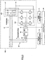
- Fig. 3 is a diagram for illustrating an example of a circuit configuration of the converter 100.
- the converter 100 includes terminals R, S and T which are connected to the AC power supply and terminals P and N which are connected to the DC link 300.
- the converter 100 includes the rectifier (powering circuit part) 102 which is formed of a three-phase diode bridge including six diodes, and a bridge circuit (regenerating circuit part) 104 which is formed of a three-phase inverter including six transistors. It is noted that in Fig. 3 a flow of the electric power at the time of a powering mode and a flow of the electric power at the time of a regenerating mode are indicated by arrows.
- the rectifier 102 performs a conversion operation (powering operation) from the alternating electric power to the direct electric power in the DC link 300 with diode rectification.
- the bridge circuit 104 performs a PWM (Pulse Width Modulation) control according to a driving signal output from a PWM generator 71 to implement a conversion operation (power supply regenerating operation) from the direct electric power in the DC link 300 to the alternating electric power in the alternating power supply.
- the bridge circuit 104 controls magnitude of the alternating electric power (alternating electric current) between the alternating power supply and the bridge circuit 104 and magnitude of the direct electric power (direct electric current) of the DC link 300 during the power supply regenerating operation.
- the converter 100 includes a regenerative line 82 connected to a powering line 81 in parallel.
- the powering line 81 is between the alternating power supply and the motor driver circuit and has the rectifier 102 provided therein.
- the regenerative line 82 is connected to the input and the output of the rectifier 102 in parallel.
- One end of the regenerative line 82 is connected to an alternating current line part of the powering line 81 on the input side of the rectifier 102, and another end of the regenerative line 82 is connected to a direct current line part of the powering line 81 on the output side of the rectifier 102.
- the regenerative line 82 has the bridge circuit 104 and a harmonics component reducing part 63 inserted in series therein.
- the bridge circuit 104 is a converting part which converts the direct electric power between the output side of the rectifier 102 and the input side of the motor driver circuit 51 (see Fig. 2 ) into the alternating electric power.
- the alternating electric power output by the power conversion operation of the bridge circuit 104 is input to the harmonics component reducing part 63.
- the harmonics component reducing part 63 may function as a low-pass filter.
- the harmonics component reducing part 63 includes plural inductors inserted to the respective phases of R, S and T in series and capacitors (capacitors) connected between the inductors, for example.
- the harmonics component reducing part 63 may have a Y-connection configuration in which plural capacitors whose ends are connected to the respective phases are commonly connected at a neutral point, as illustrated in Fig. 4 .
- the harmonics component reducing part 63 may have a delta connection configuration in which the capacitors are connected between the respective phases, as illustrated in Fig. 5 . Further, the harmonics component reducing part 63 may be configured such that only the inductors are inserted to the respective phases in series.
- the injection molding machine 1 includes, as a controlling part of the converter 100, the controller 26, the PWM generator 71 which generates a PWM driving signal, and a phase detecting part 72 which detects a phase of the alternating voltage in a line connecting between the output side of the harmonics component reducing part 63, the alternating power supply and the input side of the rectifier 102.
- the controller 26 performs the PWM control of the bridge circuit 104 with the PWM generator 71 to regenerate the electric power of the servo motor 11 which is input to the bridge circuit 104 via the motor driver circuit 51.
- the controller 26 controls the regenerating operation of the bridge circuit 104 with the PWM driving signal generated by the PMW generator 71 such that the alternating current output from the bridge circuit 104 is shaped to have a shape of a sine wave.
- the PWM control has advantage over the non-PWM control in that it can reduce the harmonics current, which is generated by the switching operations of the transistors of the bridge circuit 104 and passes to the alternating power supply, and improve the power-factor at the time of regenerating.
- the controller 26 controls the regenerating operation by the power converting operation of the bridge circuit 104 with the PMW generator 71, based on a direct voltage value Vdc detected by the voltage detecting part 190 (see Fig. 2 ), an alternating current value Iacf detected by a current detecting part 61 between the alternating output side of the bridge circuit 104 and the alternating input side of the harmonics component reducing part 63, and an alternating voltage value Vacf detected by a voltage detecting part 62, such that the alternating current output from the bridge circuit 104 has a sine wave shape with a target frequency.
- a phase detecting part 72 is capable of detecting the phase of the alternating voltage based on the alternating voltage value Vacf detected by the voltage detecting part 62.
- the controller 26 generates an instruction value Ir of the alternating current by performing processes, such as a process of multiplying a voltage error output Verr, which is generated according to an error between an instruction value Vr of the direct voltage and the direct voltage value Vdc supplied from the voltage detecting part 190, by the alternating voltage value Vacf supplied from the phase detecting part 72. Then, the controller 26 supplies an current error output Ierr, which is generated according to an error between the instruction value Ir and the alternating current value Iacf supplied from the current detecting part 61, to the PMW generator 71. The PMW generator 71 compares the current error output Ierr with a predetermined carrier such as a triangle wave to generate the PWM driving signal for driving the gates of the transistors of the bridge circuit 104 to implement the regenerating operation.
- a predetermined carrier such as a triangle wave
- Fig. 6 is a functional block diagram of the controller 26 which functions as a control apparatus of the converter 100. It is noted that the control apparatus of the converter 100 may be implemented by a control apparatus other than the controller 26.
- the controller 26 includes a converter controlling part 261 and a regeneration determining part 263.
- the controller 26 includes one or more calculation processing apparatuses and a storage device for storing software (programs) and data, etc., such as a RAM and a ROM.
- the respective functional parts 261 and 263 of the controller 26 are functional parts for performing various processes for input data, using the calculation processing apparatus mainly, and are implemented by a hardware resource, a software resource or a combination thereof. The functions of the respective functional parts 261 and 263 are described with reference to Fig. 7 .
- Fig. 7 is a flowchart for illustrating an example of a method of controlling the converter 100 according to the present embodiment.
- the control process illustrated in Fig. 7 is executed by the controller 26 in connection with the regeneration of the servo motor 11 (at the time of decelerating the injection speed in the case of the servo motor 11).
- step 10 the regeneration determining part 263 acquires a voltage Vdc across the capacitor of the DC link 300 with the voltage detecting part 190 to determine the regenerating status of the motor.
- the regeneration determining part 263 determines whether the voltage Vdc of the DC link 300 is greater than a predetermined threshold voltage Vth.
- the regeneration determining part 263 determines that the motor is not in the decelerated status, that is to say, the motor does not generate the regenerative electric power if the voltage Vdc is not greater than the predetermined threshold voltage Vth. If it is determined by the regeneration determining part 263 that the voltage Vdc is not greater than a threshold voltage Vth (i.e., it is determined that the motor does not generate the regenerative electric power), the converter controlling part 261 controls the transistors of the bridge circuit 104 such that all the transistors are tuned off, thereby not performing the regenerating operation of the bridge circuit 104. On the other hand, if the voltage Vdc is greater than the predetermined threshold voltage Vth, the regeneration determining part 263 determines that the motor is in the decelerated status, that is to say, the motor generates the regenerative electric power.
- step 14 the converter controlling part 261 starts the regenerating operation, if the voltage Vdc is not greater than the threshold voltage Vth based on the determination result of the regeneration determining part 263.
- step 16 the converter controlling part 261 performs the switching operations of the transistors of the bridge circuit 104 with the PWM control such that the alternating current output from the bridge circuit 104 has a shape of a sine wave (step 16).
- the converter controlling part 261 stops the regenerating operation of the bridge circuit 104 by tuning off all the transistors of bridge circuit 104, if it is determined by the regeneration determining part 263 that a regeneration stop criterion is met. For example, the regeneration determining part 263 determines that the regeneration stop criterion is met, if the direct voltage value detected by the voltage detecting part 190 is smaller than a predetermined voltage value which is smaller than the threshold voltage Vth and a peak value of the alternating current detected by the current detecting part 61 is smaller than a predetermined current value.
- the regenerative line 82 is provided in parallel to the powering line 81, the regenerative electric power can be effectively recovered, thereby reducing the energy consumption.
- the bridge circuit 104 and the harmonics component reducing part 63 have only the regenerative current passing therethrough (i.e., the powering current does not pass through the bridge circuit 104 and the harmonics component reducing part 63), a rating can be decreased in comparison with a case where a powering line and a regenerative line is common. For example, it is possible to select the switching elements such as the transistors, the inductors, etc., according not to the powering electric power but instead to regenerative electric power. Further, the regeneration by the PWM control using the PMW generator 71 increases the power factor.
- a voltage or a current as a dimension of a physical quantity is used for control; however, substantially the same control can be performed by equivalently using other dimensions of a physical quantity such as energy.
Landscapes
- Engineering & Computer Science (AREA)
- Power Engineering (AREA)
- Manufacturing & Machinery (AREA)
- Mechanical Engineering (AREA)
- Injection Moulding Of Plastics Or The Like (AREA)
- Inverter Devices (AREA)
- Control Of Ac Motors In General (AREA)
Claims (2)
- Machine de moulage par injection (1), comprenant :un moteur (11, 24, 42, 44) ;un circuit de commande (51, 52, 53, 54) qui entraîne le moteur (11, 24, 42, 44) ;caractérisée parune partie de redressement (102) qui alimente en électricité le circuit de commande (51, 52, 53, 54) ;une ligne de régénération (82) d'alimentation électrique de régénération du moteur (11, 24, 42, 44) connectée à la partie de redressement (102) en parallèle ; etune partie de conversion (104) et une partie de réduction des composantes harmoniques (63) prévue dans la ligne de régénération (82), la partie de conversion (104) convertissant l'alimentation électrique continue entre le circuit de commande (51, 52, 53, 54) et la partie de redressement (102) en une alimentation électrique alternative qui est fournie à la partie de réduction des composantes harmoniques (63) ; etune partie de commande (26) qui est configurée pour commander un fonctionnement de la partie de conversion (104),dans laquelle la partie de commande (26) est configurée pour commander une opération de régénération de la partie de conversion (104) en fonction d'une tension continue entre le circuit de commande (51, 52, 53, 54) et la partie de redressement (102),dans laquelle la partie de commande (26) est configurée pour mettre en oeuvre une commande PWM de la partie de conversion (104) sur la base de la tension continue entre le circuit de commande (51, 52, 53, 54) et la partie de redressement (102), une tension alternative entre la partie de conversion (104) et la partie de réduction des composantes harmoniques (63), et une tension alternative du côté de la sortie de la partie de réduction des composantes harmoniques (63) ; etdans laquelle la partie de commande (26) est configurée pour déterminer qu'un critère d'arrêt de la régénération est satisfait et pour arrêter l'opération de régénération de la partie de conversion (104) quand une valeur de tension continue entre le circuit de commande (51, 52, 53, 54) et la partie de redressement (102) est inférieure à une valeur de tension prédéterminée (vth) et une valeur pic d'un courant alternatif entre la partie de conversion (104) et la partie de réduction des composantes harmoniques (63) est inférieure à une valeur de courant prédéterminée.
- Machine de moulage par injection selon la revendication 1, dans laquelle la partie de conversion (104) fonctionne de sorte qu'une forme d'onde du courant électrique de l'alimentation électrique alternative convertie corresponde à une forme d'onde sinusoïdale.
Applications Claiming Priority (1)
| Application Number | Priority Date | Filing Date | Title |
|---|---|---|---|
| JP2011163695A JP5801128B2 (ja) | 2011-07-26 | 2011-07-26 | 射出成形機 |
Publications (3)
| Publication Number | Publication Date |
|---|---|
| EP2552010A2 EP2552010A2 (fr) | 2013-01-30 |
| EP2552010A3 EP2552010A3 (fr) | 2017-05-17 |
| EP2552010B1 true EP2552010B1 (fr) | 2019-09-11 |
Family
ID=46603516
Family Applications (1)
| Application Number | Title | Priority Date | Filing Date |
|---|---|---|---|
| EP12005451.5A Active EP2552010B1 (fr) | 2011-07-26 | 2012-07-26 | Machine de moulage à injection |
Country Status (5)
| Country | Link |
|---|---|
| US (1) | US8994314B2 (fr) |
| EP (1) | EP2552010B1 (fr) |
| JP (1) | JP5801128B2 (fr) |
| CN (1) | CN102896732B (fr) |
| CA (1) | CA2783532C (fr) |
Families Citing this family (4)
| Publication number | Priority date | Publication date | Assignee | Title |
|---|---|---|---|---|
| JP6234869B2 (ja) * | 2014-03-31 | 2017-11-22 | 住友重機械工業株式会社 | 射出成形機 |
| JP6415838B2 (ja) | 2014-03-31 | 2018-10-31 | 住友重機械工業株式会社 | 射出成形機 |
| JP6234868B2 (ja) * | 2014-03-31 | 2017-11-22 | 住友重機械工業株式会社 | 射出成形機 |
| JP6802229B2 (ja) * | 2018-09-25 | 2020-12-16 | ファナック株式会社 | 射出成形機の表示装置及び表示システム |
Family Cites Families (22)
| Publication number | Priority date | Publication date | Assignee | Title |
|---|---|---|---|---|
| JPS6166573A (ja) | 1984-09-06 | 1986-04-05 | Toshiba Corp | 電力変換装置 |
| JP2544522B2 (ja) * | 1990-12-28 | 1996-10-16 | 三菱電機株式会社 | 電力回生装置 |
| JPH0533640U (ja) * | 1991-10-09 | 1993-04-30 | 三菱電機株式会社 | 電力回生装置 |
| JPH05244788A (ja) * | 1992-02-27 | 1993-09-21 | Fuji Electric Co Ltd | 電力回生装置 |
| JPH08228490A (ja) | 1995-02-22 | 1996-09-03 | Hitachi Ltd | 電力変換装置 |
| JPH08251947A (ja) * | 1995-03-15 | 1996-09-27 | Hitachi Ltd | 電力変換装置の回生制御装置 |
| JPH11289793A (ja) * | 1998-03-31 | 1999-10-19 | Sumitomo Heavy Ind Ltd | 高調波抑制型電源回生コンバータを備えた電動射出成形機 |
| JPH11289794A (ja) * | 1998-03-31 | 1999-10-19 | Sumitomo Heavy Ind Ltd | 電源回生コンバータ |
| JP3250180B2 (ja) * | 1998-06-17 | 2002-01-28 | 住友重機械工業株式会社 | 電動射出成形機の可塑化/計量工程における除圧方法 |
| JP2000201492A (ja) * | 1998-12-28 | 2000-07-18 | Ishikawajima Transport Machinery Co Ltd | 電動機の駆動方法及び装置 |
| JP3616527B2 (ja) * | 1999-08-30 | 2005-02-02 | 山洋電気株式会社 | 電動機駆動用電力変換装置 |
| JP3794252B2 (ja) * | 2000-07-26 | 2006-07-05 | 東芝機械株式会社 | 電動式射出成形機および電動式射出成形機の射出制御方法 |
| DE10164933B4 (de) * | 2001-10-23 | 2007-03-08 | Siemens Ag | Elektrische Kunststoffspritzgießmaschine |
| JP2004050814A (ja) * | 2002-05-28 | 2004-02-19 | Toshiba Mach Co Ltd | ハイブリッド給電型射出成形機システム |
| CN1264269C (zh) | 2002-12-13 | 2006-07-12 | 永大机电工业股份有限公司 | 升降设备的电力控制装置 |
| US7176648B2 (en) * | 2004-05-18 | 2007-02-13 | Husky Injection Molding Systems Ltd. | Energy management apparatus and method for injection molding systems |
| JP4021431B2 (ja) | 2004-08-10 | 2007-12-12 | ファナック株式会社 | コンバータ装置、インバータ装置及びdcリンク電圧の制御方法 |
| JP2006350900A (ja) | 2005-06-20 | 2006-12-28 | Toshiba Mitsubishi-Electric Industrial System Corp | 電力変換装置 |
| JP4756559B2 (ja) * | 2008-03-28 | 2011-08-24 | 株式会社日本製鋼所 | 電動射出成形機の電力供給装置および電動射出成形機 |
| JP4879953B2 (ja) * | 2008-11-05 | 2012-02-22 | 株式会社日本製鋼所 | 電動射出成形機の電力表示方法および電力表示装置 |
| DE102009001337B4 (de) * | 2009-03-04 | 2024-12-12 | Ningbo Zhafir Plastics Machinery Manufacturing Co., Ltd. | Spritzgießmaschine und Verfahren zum Betrieb einer Spritzgießmaschine |
| JP2011151918A (ja) * | 2010-01-20 | 2011-08-04 | Fanuc Ltd | 電源回生機能を有するモータ駆動装置 |
-
2011
- 2011-07-26 JP JP2011163695A patent/JP5801128B2/ja not_active Expired - Fee Related
-
2012
- 2012-07-24 CA CA2783532A patent/CA2783532C/fr not_active Expired - Fee Related
- 2012-07-24 CN CN201210258069.5A patent/CN102896732B/zh active Active
- 2012-07-24 US US13/556,305 patent/US8994314B2/en not_active Expired - Fee Related
- 2012-07-26 EP EP12005451.5A patent/EP2552010B1/fr active Active
Non-Patent Citations (1)
| Title |
|---|
| None * |
Also Published As
| Publication number | Publication date |
|---|---|
| CA2783532C (fr) | 2016-01-19 |
| US20130026956A1 (en) | 2013-01-31 |
| CN102896732A (zh) | 2013-01-30 |
| US8994314B2 (en) | 2015-03-31 |
| CN102896732B (zh) | 2015-11-18 |
| CA2783532A1 (fr) | 2013-01-26 |
| JP2013027987A (ja) | 2013-02-07 |
| JP5801128B2 (ja) | 2015-10-28 |
| EP2552010A3 (fr) | 2017-05-17 |
| EP2552010A2 (fr) | 2013-01-30 |
Similar Documents
| Publication | Publication Date | Title |
|---|---|---|
| JP5653428B2 (ja) | 射出成形機及び電源回生コンバータ | |
| EP2522481B1 (fr) | Machine de moulage à injection | |
| EP2552011B1 (fr) | Machine de moulage à injection | |
| EP2664439B1 (fr) | Machine de moulage par injection et dispositif de régénération d'énergie | |
| EP2552010B1 (fr) | Machine de moulage à injection | |
| EP2587660B1 (fr) | Machine de moulage par injection et convertisseur à récupération pour source d'alimentation | |
| EP2896493B1 (fr) | Machine de moulage à injection | |
| JP5512584B2 (ja) | 射出成形機及び電源コンバータの制御装置 | |
| JP2013027986A (ja) | 射出成形機 | |
| CN108688108B (zh) | 注射成型机及工业用机械 |
Legal Events
| Date | Code | Title | Description |
|---|---|---|---|
| PUAI | Public reference made under article 153(3) epc to a published international application that has entered the european phase |
Free format text: ORIGINAL CODE: 0009012 |
|
| AK | Designated contracting states |
Kind code of ref document: A2 Designated state(s): AL AT BE BG CH CY CZ DE DK EE ES FI FR GB GR HR HU IE IS IT LI LT LU LV MC MK MT NL NO PL PT RO RS SE SI SK SM TR |
|
| AX | Request for extension of the european patent |
Extension state: BA ME |
|
| PUAL | Search report despatched |
Free format text: ORIGINAL CODE: 0009013 |
|
| AK | Designated contracting states |
Kind code of ref document: A3 Designated state(s): AL AT BE BG CH CY CZ DE DK EE ES FI FR GB GR HR HU IE IS IT LI LT LU LV MC MK MT NL NO PL PT RO RS SE SI SK SM TR |
|
| AX | Request for extension of the european patent |
Extension state: BA ME |
|
| RIC1 | Information provided on ipc code assigned before grant |
Ipc: H02P 6/00 20160101AFI20170412BHEP |
|
| STAA | Information on the status of an ep patent application or granted ep patent |
Free format text: STATUS: REQUEST FOR EXAMINATION WAS MADE |
|
| 17P | Request for examination filed |
Effective date: 20171116 |
|
| RBV | Designated contracting states (corrected) |
Designated state(s): AL AT BE BG CH CY CZ DE DK EE ES FI FR GB GR HR HU IE IS IT LI LT LU LV MC MK MT NL NO PL PT RO RS SE SI SK SM TR |
|
| GRAP | Despatch of communication of intention to grant a patent |
Free format text: ORIGINAL CODE: EPIDOSNIGR1 |
|
| STAA | Information on the status of an ep patent application or granted ep patent |
Free format text: STATUS: GRANT OF PATENT IS INTENDED |
|
| INTG | Intention to grant announced |
Effective date: 20190402 |
|
| GRAS | Grant fee paid |
Free format text: ORIGINAL CODE: EPIDOSNIGR3 |
|
| GRAA | (expected) grant |
Free format text: ORIGINAL CODE: 0009210 |
|
| STAA | Information on the status of an ep patent application or granted ep patent |
Free format text: STATUS: THE PATENT HAS BEEN GRANTED |
|
| AK | Designated contracting states |
Kind code of ref document: B1 Designated state(s): AL AT BE BG CH CY CZ DE DK EE ES FI FR GB GR HR HU IE IS IT LI LT LU LV MC MK MT NL NO PL PT RO RS SE SI SK SM TR |
|
| REG | Reference to a national code |
Ref country code: GB Ref legal event code: FG4D |
|
| REG | Reference to a national code |
Ref country code: CH Ref legal event code: EP |
|
| REG | Reference to a national code |
Ref country code: AT Ref legal event code: REF Ref document number: 1179798 Country of ref document: AT Kind code of ref document: T Effective date: 20190915 |
|
| REG | Reference to a national code |
Ref country code: DE Ref legal event code: R096 Ref document number: 602012063798 Country of ref document: DE Ref country code: IE Ref legal event code: FG4D |
|
| REG | Reference to a national code |
Ref country code: NL Ref legal event code: MP Effective date: 20190911 |
|
| REG | Reference to a national code |
Ref country code: LT Ref legal event code: MG4D |
|
| PG25 | Lapsed in a contracting state [announced via postgrant information from national office to epo] |
Ref country code: SE Free format text: LAPSE BECAUSE OF FAILURE TO SUBMIT A TRANSLATION OF THE DESCRIPTION OR TO PAY THE FEE WITHIN THE PRESCRIBED TIME-LIMIT Effective date: 20190911 Ref country code: NO Free format text: LAPSE BECAUSE OF FAILURE TO SUBMIT A TRANSLATION OF THE DESCRIPTION OR TO PAY THE FEE WITHIN THE PRESCRIBED TIME-LIMIT Effective date: 20191211 Ref country code: FI Free format text: LAPSE BECAUSE OF FAILURE TO SUBMIT A TRANSLATION OF THE DESCRIPTION OR TO PAY THE FEE WITHIN THE PRESCRIBED TIME-LIMIT Effective date: 20190911 Ref country code: HR Free format text: LAPSE BECAUSE OF FAILURE TO SUBMIT A TRANSLATION OF THE DESCRIPTION OR TO PAY THE FEE WITHIN THE PRESCRIBED TIME-LIMIT Effective date: 20190911 Ref country code: BG Free format text: LAPSE BECAUSE OF FAILURE TO SUBMIT A TRANSLATION OF THE DESCRIPTION OR TO PAY THE FEE WITHIN THE PRESCRIBED TIME-LIMIT Effective date: 20191211 Ref country code: LT Free format text: LAPSE BECAUSE OF FAILURE TO SUBMIT A TRANSLATION OF THE DESCRIPTION OR TO PAY THE FEE WITHIN THE PRESCRIBED TIME-LIMIT Effective date: 20190911 |
|
| PG25 | Lapsed in a contracting state [announced via postgrant information from national office to epo] |
Ref country code: ES Free format text: LAPSE BECAUSE OF FAILURE TO SUBMIT A TRANSLATION OF THE DESCRIPTION OR TO PAY THE FEE WITHIN THE PRESCRIBED TIME-LIMIT Effective date: 20190911 Ref country code: GR Free format text: LAPSE BECAUSE OF FAILURE TO SUBMIT A TRANSLATION OF THE DESCRIPTION OR TO PAY THE FEE WITHIN THE PRESCRIBED TIME-LIMIT Effective date: 20191212 Ref country code: AL Free format text: LAPSE BECAUSE OF FAILURE TO SUBMIT A TRANSLATION OF THE DESCRIPTION OR TO PAY THE FEE WITHIN THE PRESCRIBED TIME-LIMIT Effective date: 20190911 Ref country code: LV Free format text: LAPSE BECAUSE OF FAILURE TO SUBMIT A TRANSLATION OF THE DESCRIPTION OR TO PAY THE FEE WITHIN THE PRESCRIBED TIME-LIMIT Effective date: 20190911 Ref country code: RS Free format text: LAPSE BECAUSE OF FAILURE TO SUBMIT A TRANSLATION OF THE DESCRIPTION OR TO PAY THE FEE WITHIN THE PRESCRIBED TIME-LIMIT Effective date: 20190911 |
|
| PG25 | Lapsed in a contracting state [announced via postgrant information from national office to epo] |
Ref country code: PT Free format text: LAPSE BECAUSE OF FAILURE TO SUBMIT A TRANSLATION OF THE DESCRIPTION OR TO PAY THE FEE WITHIN THE PRESCRIBED TIME-LIMIT Effective date: 20200113 Ref country code: RO Free format text: LAPSE BECAUSE OF FAILURE TO SUBMIT A TRANSLATION OF THE DESCRIPTION OR TO PAY THE FEE WITHIN THE PRESCRIBED TIME-LIMIT Effective date: 20190911 Ref country code: PL Free format text: LAPSE BECAUSE OF FAILURE TO SUBMIT A TRANSLATION OF THE DESCRIPTION OR TO PAY THE FEE WITHIN THE PRESCRIBED TIME-LIMIT Effective date: 20190911 Ref country code: NL Free format text: LAPSE BECAUSE OF FAILURE TO SUBMIT A TRANSLATION OF THE DESCRIPTION OR TO PAY THE FEE WITHIN THE PRESCRIBED TIME-LIMIT Effective date: 20190911 Ref country code: IT Free format text: LAPSE BECAUSE OF FAILURE TO SUBMIT A TRANSLATION OF THE DESCRIPTION OR TO PAY THE FEE WITHIN THE PRESCRIBED TIME-LIMIT Effective date: 20190911 Ref country code: EE Free format text: LAPSE BECAUSE OF FAILURE TO SUBMIT A TRANSLATION OF THE DESCRIPTION OR TO PAY THE FEE WITHIN THE PRESCRIBED TIME-LIMIT Effective date: 20190911 |
|
| PG25 | Lapsed in a contracting state [announced via postgrant information from national office to epo] |
Ref country code: CZ Free format text: LAPSE BECAUSE OF FAILURE TO SUBMIT A TRANSLATION OF THE DESCRIPTION OR TO PAY THE FEE WITHIN THE PRESCRIBED TIME-LIMIT Effective date: 20190911 Ref country code: SM Free format text: LAPSE BECAUSE OF FAILURE TO SUBMIT A TRANSLATION OF THE DESCRIPTION OR TO PAY THE FEE WITHIN THE PRESCRIBED TIME-LIMIT Effective date: 20190911 Ref country code: SK Free format text: LAPSE BECAUSE OF FAILURE TO SUBMIT A TRANSLATION OF THE DESCRIPTION OR TO PAY THE FEE WITHIN THE PRESCRIBED TIME-LIMIT Effective date: 20190911 Ref country code: IS Free format text: LAPSE BECAUSE OF FAILURE TO SUBMIT A TRANSLATION OF THE DESCRIPTION OR TO PAY THE FEE WITHIN THE PRESCRIBED TIME-LIMIT Effective date: 20200224 |
|
| REG | Reference to a national code |
Ref country code: DE Ref legal event code: R097 Ref document number: 602012063798 Country of ref document: DE |
|
| PLBE | No opposition filed within time limit |
Free format text: ORIGINAL CODE: 0009261 |
|
| STAA | Information on the status of an ep patent application or granted ep patent |
Free format text: STATUS: NO OPPOSITION FILED WITHIN TIME LIMIT |
|
| PG2D | Information on lapse in contracting state deleted |
Ref country code: IS |
|
| PG25 | Lapsed in a contracting state [announced via postgrant information from national office to epo] |
Ref country code: DK Free format text: LAPSE BECAUSE OF FAILURE TO SUBMIT A TRANSLATION OF THE DESCRIPTION OR TO PAY THE FEE WITHIN THE PRESCRIBED TIME-LIMIT Effective date: 20190911 Ref country code: IS Free format text: LAPSE BECAUSE OF FAILURE TO SUBMIT A TRANSLATION OF THE DESCRIPTION OR TO PAY THE FEE WITHIN THE PRESCRIBED TIME-LIMIT Effective date: 20200112 |
|
| 26N | No opposition filed |
Effective date: 20200615 |
|
| PG25 | Lapsed in a contracting state [announced via postgrant information from national office to epo] |
Ref country code: SI Free format text: LAPSE BECAUSE OF FAILURE TO SUBMIT A TRANSLATION OF THE DESCRIPTION OR TO PAY THE FEE WITHIN THE PRESCRIBED TIME-LIMIT Effective date: 20190911 |
|
| REG | Reference to a national code |
Ref country code: AT Ref legal event code: UEP Ref document number: 1179798 Country of ref document: AT Kind code of ref document: T Effective date: 20190911 |
|
| PG25 | Lapsed in a contracting state [announced via postgrant information from national office to epo] |
Ref country code: MC Free format text: LAPSE BECAUSE OF FAILURE TO SUBMIT A TRANSLATION OF THE DESCRIPTION OR TO PAY THE FEE WITHIN THE PRESCRIBED TIME-LIMIT Effective date: 20190911 |
|
| REG | Reference to a national code |
Ref country code: CH Ref legal event code: PL |
|
| GBPC | Gb: european patent ceased through non-payment of renewal fee |
Effective date: 20200726 |
|
| REG | Reference to a national code |
Ref country code: BE Ref legal event code: MM Effective date: 20200731 |
|
| PG25 | Lapsed in a contracting state [announced via postgrant information from national office to epo] |
Ref country code: LI Free format text: LAPSE BECAUSE OF NON-PAYMENT OF DUE FEES Effective date: 20200731 Ref country code: CH Free format text: LAPSE BECAUSE OF NON-PAYMENT OF DUE FEES Effective date: 20200731 Ref country code: FR Free format text: LAPSE BECAUSE OF NON-PAYMENT OF DUE FEES Effective date: 20200731 Ref country code: GB Free format text: LAPSE BECAUSE OF NON-PAYMENT OF DUE FEES Effective date: 20200726 Ref country code: LU Free format text: LAPSE BECAUSE OF NON-PAYMENT OF DUE FEES Effective date: 20200726 |
|
| PG25 | Lapsed in a contracting state [announced via postgrant information from national office to epo] |
Ref country code: BE Free format text: LAPSE BECAUSE OF NON-PAYMENT OF DUE FEES Effective date: 20200731 |
|
| PG25 | Lapsed in a contracting state [announced via postgrant information from national office to epo] |
Ref country code: IE Free format text: LAPSE BECAUSE OF NON-PAYMENT OF DUE FEES Effective date: 20200726 |
|
| PGFP | Annual fee paid to national office [announced via postgrant information from national office to epo] |
Ref country code: AT Payment date: 20210625 Year of fee payment: 10 |
|
| PG25 | Lapsed in a contracting state [announced via postgrant information from national office to epo] |
Ref country code: TR Free format text: LAPSE BECAUSE OF FAILURE TO SUBMIT A TRANSLATION OF THE DESCRIPTION OR TO PAY THE FEE WITHIN THE PRESCRIBED TIME-LIMIT Effective date: 20190911 Ref country code: MT Free format text: LAPSE BECAUSE OF FAILURE TO SUBMIT A TRANSLATION OF THE DESCRIPTION OR TO PAY THE FEE WITHIN THE PRESCRIBED TIME-LIMIT Effective date: 20190911 Ref country code: CY Free format text: LAPSE BECAUSE OF FAILURE TO SUBMIT A TRANSLATION OF THE DESCRIPTION OR TO PAY THE FEE WITHIN THE PRESCRIBED TIME-LIMIT Effective date: 20190911 |
|
| PG25 | Lapsed in a contracting state [announced via postgrant information from national office to epo] |
Ref country code: MK Free format text: LAPSE BECAUSE OF FAILURE TO SUBMIT A TRANSLATION OF THE DESCRIPTION OR TO PAY THE FEE WITHIN THE PRESCRIBED TIME-LIMIT Effective date: 20190911 |
|
| REG | Reference to a national code |
Ref country code: AT Ref legal event code: MM01 Ref document number: 1179798 Country of ref document: AT Kind code of ref document: T Effective date: 20220726 |
|
| PG25 | Lapsed in a contracting state [announced via postgrant information from national office to epo] |
Ref country code: AT Free format text: LAPSE BECAUSE OF NON-PAYMENT OF DUE FEES Effective date: 20220726 |
|
| PGFP | Annual fee paid to national office [announced via postgrant information from national office to epo] |
Ref country code: DE Payment date: 20240529 Year of fee payment: 13 |
|
| REG | Reference to a national code |
Ref country code: DE Ref legal event code: R119 Ref document number: 602012063798 Country of ref document: DE |
|
| PG25 | Lapsed in a contracting state [announced via postgrant information from national office to epo] |
Ref country code: DE Free format text: LAPSE BECAUSE OF NON-PAYMENT OF DUE FEES Effective date: 20260203 |