EP2552023A2 - Vorrichtung zur Steuerung eines Elektrohaushaltsgeräts, das mit einem optischen Schalter mit berührungsempfindlicher Taste ausgestattet ist - Google Patents
Vorrichtung zur Steuerung eines Elektrohaushaltsgeräts, das mit einem optischen Schalter mit berührungsempfindlicher Taste ausgestattet ist Download PDFInfo
- Publication number
- EP2552023A2 EP2552023A2 EP12177903A EP12177903A EP2552023A2 EP 2552023 A2 EP2552023 A2 EP 2552023A2 EP 12177903 A EP12177903 A EP 12177903A EP 12177903 A EP12177903 A EP 12177903A EP 2552023 A2 EP2552023 A2 EP 2552023A2
- Authority
- EP
- European Patent Office
- Prior art keywords
- receiver
- cover
- transmitter
- control device
- touch
- Prior art date
- Legal status (The legal status is an assumption and is not a legal conclusion. Google has not performed a legal analysis and makes no representation as to the accuracy of the status listed.)
- Granted
Links
Images

Classifications
-
- H—ELECTRICITY
- H03—ELECTRONIC CIRCUITRY
- H03K—PULSE TECHNIQUE
- H03K17/00—Electronic switching or gating, i.e. not by contact-making and –breaking
- H03K17/94—Electronic switching or gating, i.e. not by contact-making and –breaking characterised by the way in which the control signals are generated
- H03K17/96—Touch switches
- H03K17/9627—Optical touch switches
- H03K17/9631—Optical touch switches using a light source as part of the switch
-
- F—MECHANICAL ENGINEERING; LIGHTING; HEATING; WEAPONS; BLASTING
- F24—HEATING; RANGES; VENTILATING
- F24C—DOMESTIC STOVES OR RANGES ; DETAILS OF DOMESTIC STOVES OR RANGES, OF GENERAL APPLICATION
- F24C7/00—Stoves or ranges heated by electric energy
- F24C7/08—Arrangement or mounting of control or safety devices
- F24C7/082—Arrangement or mounting of control or safety devices on ranges, e.g. control panels, illumination
- F24C7/083—Arrangement or mounting of control or safety devices on ranges, e.g. control panels, illumination on tops, hot plates
-
- H—ELECTRICITY
- H03—ELECTRONIC CIRCUITRY
- H03K—PULSE TECHNIQUE
- H03K2217/00—Indexing scheme related to electronic switching or gating, i.e. not by contact-making or -breaking covered by H03K17/00
- H03K2217/94—Indexing scheme related to electronic switching or gating, i.e. not by contact-making or -breaking covered by H03K17/00 characterised by the way in which the control signal is generated
- H03K2217/941—Indexing scheme related to electronic switching or gating, i.e. not by contact-making or -breaking covered by H03K17/00 characterised by the way in which the control signal is generated using an optical detector
- H03K2217/94116—Indexing scheme related to electronic switching or gating, i.e. not by contact-making or -breaking covered by H03K17/00 characterised by the way in which the control signal is generated using an optical detector increasing reliability, fail-safe
Definitions
- the present invention relates to a control device of an appliance.
- the optical switch is disposed behind the wall at least partially transparent to infrared radiation.
- the optical switch comprises an emitter emitting infrared radiation, an auxiliary emitter emitting infrared radiation, and a receiver receiving at least partly infrared radiation emitted by the emitter and at least partly infrared radiation emitted by the auxiliary emitter.
- the receiver generates at least one reception signal as a function of the infrared radiation received from the transmitter and / or from the auxiliary transmitter.
- the transmitter and the receiver are arranged in a cache.
- the cover comprises a partition wall formed between the transmitter and the receiver, peripheral walls formed around the transmitter and the receiver.
- the auxiliary transmitter is disposed outside the cache comprising the transmitter and the receiver.
- control devices of a household appliance having the peripheral walls of the cover formed around the full emitter and receiver over their entire surface have the disadvantage of preventing the infrared radiation emitted by the auxiliary transmitter from reaching laterally the receiver.
- control devices of a household appliance do not make it possible to effectively test the operation of the acquisition chain of a touch-sensitive optical switch by means of the auxiliary transmitter from the receiver to a communication device.
- analog / digital conversion of a control unit comprising for example a microcontroller, and in particular to detect a malfunction of the touch-sensitive optical switch.
- control devices of a household appliance without a peripheral wall of the cover formed between the receiver and the auxiliary transmitter have the drawback of allowing too much light radiation to pass from a light source external to the control device to detect a touch of a user's finger on the touch-sensitive optical switch, particularly when the light radiation emitted by the external light source laterally reaches the receiver.
- This light source outside the control device may be for example the sun, or a lighting device of the room in which is located the appliance.
- the object of the present invention is to solve the aforementioned drawbacks and to propose a device for controlling an electrical household appliance making it possible to secure the operation of a touch-sensitive optical switch having at least one auxiliary transmitter while guaranteeing the detection of a press the touch-sensitive optical switch regardless of the light conditions outside the control device.
- one of the peripheral walls of said cover formed between said at least one receiver and said at least one auxiliary transmitter forming a partition wall comprises at least one opening for the passage of at least a portion of the infrared radiation emitted by said at least one auxiliary transmitter to said at least one receiver so as to determine a malfunction of said at least one touch-sensitive optical switch according to said at least one reception signal received by said at least one receiver from said at least one auxiliary transmitter .
- the peripheral wall of the cover formed between said at least one receiver and said at least one auxiliary transmitter comprising at least one opening for the passage of at least a portion of the infrared radiation emitted by said at least one auxiliary transmitter to said at least one receiver makes it possible to test the operation of at least one touch-sensitive optical switch by means of said at least one auxiliary transmitter while guaranteeing the detection of a support on said at least one touch-sensitive optical switch whatever the light conditions. external to the control device.
- peripheral wall of the cover formed between said at least one receiver and said at least one auxiliary transmitter provided with said at least one passage opening makes it possible to improve the ambient noise immunity of the control device related to a strong illumination. , especially when a user's finger is positioned above said at least one touch-sensitive optical switch.
- the peripheral wall of the cover formed between said at least one receiver and said at least one auxiliary transmitter provided with said at least one passage opening makes it possible to overcome the nuisance caused by a strong illumination from a light source.
- the external light source can be for example the sun or a lighting device of the room in which the appliance is located.
- said at least one through opening of said peripheral wall of said cover extends between a printed circuit board and a rim of said peripheral wall of said cover formed between said at least one receiver and said at least one auxiliary transmitter, said printed circuit board supporting said at least one touch-sensitive optical switch.
- said at least one passage opening of the peripheral wall of the cover formed between said at least one receiver and said at least one auxiliary transmitter extends over part of the height of this peripheral wall of the cover.
- said at least one passage opening of the peripheral wall of the cover formed between said at least one receiver and said at least one auxiliary transmitter extends only on the lower part of this peripheral wall of the cover.
- said at least one passage opening of the peripheral wall of the cover formed between said at least one receiver and said at least one auxiliary transmitter makes it possible to let at least a portion of the infrared radiation emitted by said at least one auxiliary transmitter to said at least one receiver, and said peripheral wall of the cover formed between said at least one receiver and said at least one transmitter auxiliary device provided with said at least one passage opening blocks the light rays from a light source external to the control device directed laterally relative to said at least one receiver.
- the present invention also relates, in a second aspect, to a household appliance, in particular a cooking hob, comprising a control device described above.
- This appliance has advantages and characteristics similar to those described above in relation to the control device according to the invention.
- This appliance may be a cooking appliance, in particular a hob for domestic use, a cooking oven for domestic use or a stove, or a washing machine, in particular a washing machine and / or drying clothes. for domestic use, or a domestic dishwashing machine, or a refrigerating appliance, in particular a refrigerator or a freezer.
- the appliance is a cooktop 1.
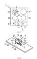
- FIG. 1 A schematic top view of a hob 1.
- Circles 10 schematize the existence of hobs 2a, 2b, 2c, 2d on which a cooking vessel 3 can be placed.
- the hob 1 comprises four cooking stoves 2a, 2b, 2c, 2d independent.
- Such a hob can be embedded or be an integral part of a work plan. It can also be associated with other cooking appliances, such as a cooking oven arranged underneath.
- Each cooking chamber 2a, 2b, 2c, 2d comprises at least one heating means.
- the heating means or means of each of said cooking heaters 2a, 2b, 2c, 2d can be supplied with electricity and / or gas. These heating means may be induction type, radiant or halogen, or gas.
- each cooking zone 2a, 2b, 2c, 2d consists of one or more heating elements.
- a single heating element can materialize each cooking chamber 2a, 2b, 2c, 2d.
- each cooking zone 2a, 2b, 2c, 2d may comprise several heating elements.
- the arrangement of the plurality of heating elements may be concentric and include for example two or three heating elements to adapt the size of the cooking stove to the size of the container to be heated.
- the arrangement of the plurality of heating elements may be adjacent, in particular either in line, in triangle or in square, and for example comprise between two and four heating elements making it possible to adapt the size of the hearth. cooking at the size of the container to be heated.
- the arrangement of the heating elements may be in the form of a matrix so as to form a hob without predetermined heating zones.
- the hob 1 comprises a hob 6, in particular glass-ceramic.
- This hob 1 comprises in the hob 6 several cooking stoves 2a, 2b, 2c, 2d.
- These cooking hearths 2a, 2b, 2c, 2d may in an embodiment as illustrated in FIG. figure 1 be constituted by one or more inductors for heating a cooking vessel 3 by the induction heating principle.
- the hob 1 comprises a touch-sensitive control device 11 as illustrated in FIG. figure 1 .
- the touch-sensitive control device 11 is preferably placed in the form of a control panel near a front edge of the hob 1.
- the touch-sensitive control device 11 is placed under the cooking plane 6.
- At least the portion of the control panel comprising the touch-sensitive control device described hereinafter can be made from a plate of material at least partially transparent to a infrared radiation, for example glass or plastic.
- the control device 11 of an appliance 1 comprises at least one touch-sensitive optical switch 4, a wall 6 being at least partially transparent to infrared radiation.
- Said at least one touch-sensitive optical switch 4 is disposed behind the wall 6 at least partially transparent to infrared radiation.
- the touch-sensitive control device 11 may comprise a plurality of touch-sensitive optical touch switches 4 independent of each other and situated under a wall 6 of the control device 11.
- the optical touch-key switches 4 are associated with means for detecting the presence of an object, in particular a finger of a user, facing these touch-sensitive optical switches 4.
- Said at least one touch-sensitive optical switch 4 comprises at least one emitter 5 emitting infrared radiation, at least one auxiliary emitter 7 emitting infrared radiation, and at least one receiver 12 receiving at least partly infrared radiation emitted by said emitter. at least one transmitter 5 and at least partly infrared radiation emitted by said at least one auxiliary transmitter 7.
- said at least one transmitter 5 and said at least one auxiliary transmitter 7 are light emitting diodes.
- said at least one receiver 12 is a phototransistor.
- the detection means associated with said at least one touch-sensitive switch 4 are adapted to detect the variation of the illumination, in particular when an object which can be a user's finger, is placed facing and / or displaced by to said at least one touch-sensitive optical switch 4.
- Said at least one touch-sensitive optical switch 4 thus makes it possible to provide detection signals from which the triggering of a control function or the setting of a value of at least one operating parameter can be carried out.
- Said at least one receiver 12 generates at least one reception signal as a function of the infrared radiation received from said at least one transmitter 5 and / or from said at least one auxiliary transmitter 7.
- the touch-sensitive control device 11 also comprises a control unit (not shown) generating at least one control signal based on positioning or moving an object in proximity to said at least one touch-sensitive optical switch 4 so as to trigger a control function or to adjust a value of a variable operating parameter.
- a control unit (not shown) generating at least one control signal based on positioning or moving an object in proximity to said at least one touch-sensitive optical switch 4 so as to trigger a control function or to adjust a value of a variable operating parameter.
- control function to be triggered by means of said at least one touch-sensitive optical switch 4 is the on / off function of an appliance 1.
- a passage opening 16 of at least a portion of the infrared radiation emitted by an auxiliary transmitter 7 to a receiver 12 formed in one of the peripheral walls 15 of the cover 13 disposed between the receiver 12 and the auxiliary transmitter 7 allows to secure the operation of a touch-sensitive optical switch 4 and to guarantee the start-up and in particular the shutdown of an appliance 1.
- the detection of a failure by the touch-sensitive control device 11 makes it possible to automatically stop the appliance 1 for safety, as well as, for example, heating means operated by the control unit. control of the household appliance 1 which can be in particular a hob.
- control function to be triggered by means of said at least one touch-sensitive optical switch is in no way limiting and may be different, in particular the control function to be triggered by means of said at least one touch-sensitive optical switch can be a validation function of a selected operating parameter.
- a variable operating parameter to be adjusted by means of said at least one touch-sensitive optical switch 4 may be the heating power of a container, or a timer that may be associated with a cooking zone.
- variable operating parameter to be adjusted by means of said at least one touch-sensitive optical switch 4 may be different.
- it may be a temperature parameter associated with a temperature probe of the household appliance, particularly when it is a cooking oven.
- the touch-sensitive control device 11 of the hob 1 comprises a control keyboard 8 generally disposed on one side of the hob 1, for example along a front edge of the hob 6.
- This control keyboard 8 comprises control means 4 in operation of the cooking stoves 2a, 2b, 2c, 2d.
- control pad 8 includes different optical touch-key switches 4 allowing the user, by simply pressing a key marked by a marking area on the hob 6, to control and / or modify the operation of one or more cooking hobs 2a, 2b, 2c, 2d.
- the marking areas of the optical touch-key switches 4 can be made by screen printing.
- the control keyboard 8 of the hob 1 communicates with a control unit.
- Said control unit is itself connected to the heating means of the hob 1 and possibly to means for detecting a container.
- the control unit thus makes it possible to control in operation the heating means or means of each cooking zone 2a, 2b, 2c, 2d and possibly to control in operation the means for detecting a container.
- the control unit communicates with the control keyboard 8 to receive from said control keyboard 8 the operating parameters of one or more cooking zones 2a, 2b, 2c, 2d controlled by the user and to send information to said keyboard. 8 concerning the state of the cooking stoves 2a, 2b, 2c, 2d and the setting of the operating parameters, such as, for example, the power level and the duration of a timer, and / or to display data on at least one display means 9 of the control keyboard 8.
- said at least one display means 9 may be a seven-segment display associated with at least one touch-sensitive optical switch 4.
- At least one display means is in no way limiting and may be different, in particular said at least one display means may be an LCD display (acronym for the English term Liquid Crystal Display) .
- Said at least one transmitter 5 and said at least one receiver 12 are arranged in a cache 13.
- the cover 13 is of substantially parallelepiped shape.
- the cover 13 comprises a partition wall 14 formed between said at least one transmitter 5 and said at least one receiver 12, peripheral walls 15 formed around said at least one transmitter 5 and said at least one receiver 12.
- the partition wall 14 of the cover 13 formed between said at least one transmitter 5 and said at least one receiver 12 is full.
- the partition wall 14 of the cover 13 is full so as to force the optical path of the infrared radiation emitted by said at least one transmitter 5 towards the wall 6, then to be reflected at least partially by the wall 6 and possibly by a finger of the user disposed vis-à-vis the optical touch switch 4 to said at least one receiver 12.
- said at least one receiver 12 receives infrared radiation indirectly from said at least one transmitter 5 by means of the partition wall 14 of the cover 13 formed between said at least one transmitter 5 and said at least one receiver 12 so to guarantee the operation of a touch-sensitive optical switch 4 and to prevent a malfunction thereof by infrared radiation emitted directly from said at least one transmitter 5.
- the cover 13 comprises at least one opening 21 formed above said at least one emitter 5 and at least one opening 22 formed above said at least one receiver 12.
- Said at least one opening 21, 22 of the cover 13 are made in the direction of the wall 6 at least partially transparent to infrared radiation.
- said at least one auxiliary transmitter 7 is disposed outside the cover 13 comprising said at least one transmitter 5 and said at least one receiver 12.
- the cover 13 may be used for a touch-sensitive optical switch 4 with or without at least one auxiliary transmitter 7 so as to standardize the cover 13 for the different types of touch-sensitive optical switch.
- the cover 13 can be used for a touch-sensitive optical switch 4 with or without at least one auxiliary transmitter 7.
- the surface covered by the cover 13 is minimized so as to reduce the cost of obtaining it.
- the size of the printed circuit board 17 can also be reduced so as to minimize its bulk and to minimize the cost of obtaining the control device 11.
- a signaling indicator associated with a touch-sensitive optical switch 4 can be placed in proximity to the latter without being obstructed by the cover 13 so as to facilitate the display of the signaling indicator when the optical switch is activated. touch key 4.
- the positioning of said at least one auxiliary transmitter 7 outside the cover 13 also facilitates the implantation of a touch-sensitive optical switch 4 on the printed circuit board 17, and in particular the positioning of said at least one receiver 12 in FIG. view of said at least one auxiliary transmitter 7.
- one of the peripheral walls 15 of the cover 13 formed between said at least one receiver 12 and said at least one auxiliary transmitter 7 forming a partition wall comprises at least one passage opening 16 of at least a part infrared radiation emitted by said at least one auxiliary transmitter 7 to said at least one receiver 12 so as to determine a malfunction of said at least one touch-sensitive optical switch 4 as a function of said at least one signal of reception received by said at least one receiver 12 from said at least one auxiliary transmitter 7.
- the peripheral wall 15 of the cover 13 formed between said at least one receiver 12 and said at least one auxiliary transmitter 7 comprising at least one passage opening 16 of at least a portion of the infrared radiation emitted by said at least one auxiliary transmitter 7 to said at least one receiver 12 makes it possible to test the operation of at least one touch-sensitive optical switch 4 by means of said at least one auxiliary transmitter 7 while guaranteeing the detection of a support on said at least one optical switch to touch button 4 regardless of the light conditions outside the control device 11.
- peripheral wall 15 of the cover 13 formed between said at least one receiver 12 and said at least one auxiliary transmitter 7 provided with said at least one through opening 16 makes it possible to improve the ambient noise immunity of the control device 11 related to a strong illumination, especially when a finger of a user is positioned above said at least one touch-sensitive optical switch 4.
- the peripheral wall 15 of the cover 13 formed between said at least one receiver 12 and said at least one auxiliary transmitter 7 provided with said at least one through opening 16 makes it possible to overcome the nuisances caused by a strong illumination coming from a light source external to the control device 11 directed laterally with respect to said at least one receiver 12, where the external light source can be for example the sun or a lighting device of the room in which the apparatus is located household appliances 1.
- Such a control device 11 of a household appliance 1 makes it possible to secure the operation of at least one touch-sensitive optical switch 4 by checking the operation of the acquisition system from said at least one receiver 12 to a device analog / digital conversion of a control unit, comprising for example a microcontroller.
- the operational security of said at least one touch-sensitive optical switch 4 is performed by at least one auxiliary transmitter 7 different from at least one transmitter 5 used for the detection of an object placed facing and / or displaced vis-à-vis at least one touch-sensitive optical switch 4, and at least one cover 13 housing said at least one emitter 5 and said at least one receiver 12 and having at least one passage opening 16 of a peripheral wall 15 of the cover 13 between said at least one receiver 12 and said at least one auxiliary transmitter 7.
- said at least one passage opening 16 of said peripheral wall 15 of the cover 13 extends between a printed circuit board 17 and a flange 18 of the peripheral wall 15 of the cover 13 formed between said at least one receiver 12 and said at least one auxiliary transmitter 7, the printed circuit board 17 supporting said at least one touch-sensitive optical switch 4.
- said at least one through opening 16 of the peripheral wall 15 of the cover 13 formed between said at least one receiver 12 and said at least one auxiliary transmitter 7 extends over part of the height of this peripheral wall 15 of the cover 13.
- said at least one passage opening 16 of the peripheral wall 15 of the cover 13 formed between said at least one receiver 12 and said at least one auxiliary transmitter 7 extends only on the lower part of this peripheral wall 15 of the cache 13.
- said at least one passage opening 16 of the peripheral wall 15 of the cover 13 formed between said at least one receiver 12 and said at least one auxiliary transmitter 7 allows at least a portion of the infrared radiation emitted by said at least one to pass through.
- least one auxiliary transmitter 7 to said at least one receiver 12, and said peripheral wall 15 of the cover 13 formed between said at least one receiver 12 and said at least one auxiliary transmitter 7 provided with said at least one passage opening 16 blocks the radii light coming from a light source external to the control device 11 directed laterally with respect to the at least one receiver 12.
- the upper part of the peripheral wall 15 of the cover 13 comprising the at least one passage opening 16 being full makes it possible to block the light rays coming from a light source external to the control device 11 directed laterally relative to the least one receiver 12.
- said at least one transmitter 5, said at least one auxiliary transmitter 7 and said at least one receiver 12 are fixed on the printed circuit board 17, for example by welding. And the lower face of the cover 13 is pressed against the upper face of the printed circuit board 17.
- the cover 13 comprises at least two positioning pads 23 respectively inserted in an opening 24 of the printed circuit board 17 so as to be positioned and locked in rotation with respect to the at least one emitter 5, auditing at least one auxiliary transmitter 7 and auditing at least one receiver 12.
- Said at least two positioning pads 23 of the cover 13 can be inserted into force respectively in an opening 24 of the printed circuit board 17 so as to ensure the fixing of the cover 13 with respect to the printed circuit board 17.
- the height of said at least one passage opening 16 of the peripheral wall 15 of the cover 16 extending from the printed circuit board 17 to the flange 18 of the peripheral wall 15 of the cover 13 is greater than the height of said at least one auxiliary transmitter 7 extending from the printed circuit board 17 to the upper face 7a of said at least one auxiliary transmitter 7.
- said at least one passage opening 16 of the peripheral wall 15 of the cover 13 formed between said at least one receiver 12 and said at least one auxiliary transmitter 7 makes it possible to let at least a portion of the infrared radiation emitted by said at least one an auxiliary transmitter 7 to said at least one receiver 12 while taking into account the infrared radiation scattering cone of said at least one auxiliary transmitter 7.
- the upper part of the peripheral wall 15 of the cover 13 comprising said at least one opening opening 16 being solid makes it possible to block the light rays coming from a light source external to the control device 11 directed laterally with respect to said at least one receiver 12.
- the height of said at least one passage opening 16 of the peripheral wall 15 of the cover 13 is less than 2.5 mm, and preferably of the order of 2.3 mm.
- the height of said at least one passage opening 16 of the peripheral wall 15 of the cover 13 is a function, in particular, of the height of said at least one auxiliary transmitter 7 and of the infrared radiation scattering cone of said at least one auxiliary transmitter 7.
- said at least one through opening 16 of the peripheral wall 15 of the cover 13 extends between two other opposite peripheral walls 15 of the cover 13.
- the width of said at least one through opening 16 of the peripheral wall 15 of the cover 13 corresponds to the distance separating the other two opposite peripheral walls 15 of the cover 13.
- said at least one passage opening 16 of the peripheral wall 15 of the cover 13 having a maximum width makes it possible to let a maximum infrared radiation from said at least one auxiliary transmitter 7 to said at least one receiver 12.
- the other two opposite peripheral walls 15 of the cover 13 between which said at least one through opening 16 of the peripheral wall 15 of the cover 13 extend extend from the printed circuit board 17 to the upper face of the cover 13.
- the thickness e of the peripheral wall 15 of the cover 15 comprising said at least one through opening 16 is less than 1 mm, and preferably of the order of 0.6 mm.
- the peripheral wall 15 of the cover 15 comprising said at least one passage opening 16 having a reduced thickness makes it possible to let a maximum infrared radiation from said at least one auxiliary transmitter 7 to said at least one receiver 12 while blocking the rays. light coming from a light source external to the control device 11 directed laterally with respect to the at least one receiver 12.
- the other peripheral walls 15 of the cover 13 formed between said at least one receiver 12 and said at least one auxiliary transmitter 7 are full.
- one of the peripheral walls 15 of the cover 13 formed around said at least one emitter 5 forming a partition wall also comprises at least one passage opening 19 disposed symmetrically with respect to said at least one passage opening 16 of the peripheral wall 15 of the cover 13 formed between said at least one receiver 12 and said at least one auxiliary transmitter 7.
- the cover 13 is symmetrical and comprises on either side of the partition wall 14 formed between the at least one emitter 5 and the at least one receiver 12 at least one passage opening 16, 19 formed in a peripheral wall. So as to avoid an assembly error of the support 13 on the printed circuit board 17 which can block the passage of at least a portion of the infrared radiation from said at least one auxiliary transmitter 7 to said at least one receiver 12 by a peripheral wall 15 full of the support 13.
- said at least one passage opening 19 formed in one of the peripheral walls 15 of the cover 13 around said at least one emitter 5 and said at least one passage opening 16 of the peripheral wall 15 of the cover 13 formed between said at least one receiver 12 and said at least one auxiliary transmitter 7 are of identical dimensions and identical positioning.
- the cover 13 comprises a contour 20 formed in the upper portion and along the peripheral walls 15 of the cover 13 so as to reduce said at least one opening 21 formed in the cover 13 above said at least one transmitter 5 and said at least one opening 22 formed in the cover 13 above said at least one receiver 12.
- the reduction of said at least one opening 21, 22 formed in the cover 13 respectively above said at least one transmitter 5 and said at least one receiver 12 makes it possible to reinforce the ambient noise immunity of the control device 11 related to high illumination, especially when a user's finger is positioned above said at least one touch-sensitive optical switch 4.
- the peripheral wall of the cover formed between said at least one receiver and said at least one auxiliary transmitter comprising at least one opening for passage of at least a portion of the infrared radiation emitted by said at least one auxiliary transmitter to said at least one receiver makes it possible to test the operation of at least one touch-sensitive optical switch by means of said at least one auxiliary transmitter while guaranteeing the detection of a support on said at least one touch-sensitive optical switch whatever the light conditions outside the control device.
- control device of an appliance may be implemented in another type of hob, with heating means that may be of the radiant or halogen type, or gas, or in another type of hob. domestic cooking appliance.
- the control device of a household appliance can also be implemented in a domestic washing apparatus, or in a domestic refrigerating appliance.
Landscapes
- Engineering & Computer Science (AREA)
- Chemical & Material Sciences (AREA)
- Combustion & Propulsion (AREA)
- Mechanical Engineering (AREA)
- General Engineering & Computer Science (AREA)
- Push-Button Switches (AREA)
- Switches Operated By Changes In Physical Conditions (AREA)
- Electronic Switches (AREA)
Applications Claiming Priority (1)
| Application Number | Priority Date | Filing Date | Title |
|---|---|---|---|
| FR1102357A FR2978634B1 (fr) | 2011-07-26 | 2011-07-26 | Dispositif de commande d'un appareil electromenager comprenant un commutateur optique a touche tactile |
Publications (3)
| Publication Number | Publication Date |
|---|---|
| EP2552023A2 true EP2552023A2 (de) | 2013-01-30 |
| EP2552023A3 EP2552023A3 (de) | 2013-02-27 |
| EP2552023B1 EP2552023B1 (de) | 2014-03-12 |
Family
ID=46545286
Family Applications (1)
| Application Number | Title | Priority Date | Filing Date |
|---|---|---|---|
| EP12177903.7A Active EP2552023B1 (de) | 2011-07-26 | 2012-07-25 | Vorrichtung zur Steuerung eines Elektrohaushaltsgeräts, das mit einem optischen Schalter mit berührungsempfindlicher Taste ausgestattet ist |
Country Status (3)
| Country | Link |
|---|---|
| EP (1) | EP2552023B1 (de) |
| ES (1) | ES2471869T3 (de) |
| FR (1) | FR2978634B1 (de) |
Cited By (1)
| Publication number | Priority date | Publication date | Assignee | Title |
|---|---|---|---|---|
| CN106330154A (zh) * | 2016-11-17 | 2017-01-11 | 糜瑞松 | 一种具有避光装置的对射型光耦 |
Family Cites Families (3)
| Publication number | Priority date | Publication date | Assignee | Title |
|---|---|---|---|---|
| DE10001955A1 (de) * | 2000-01-18 | 2001-07-19 | Gerd Reime | Opto-elektronischer Schalter |
| DE10211307A1 (de) * | 2002-03-13 | 2003-11-20 | Mechaless Systems Gmbh | Vorrichtung und Verfahren zur optoelektronischen Erkennung der Bewegung und/oder Position eines Objekts |
| US7397022B2 (en) * | 2004-04-01 | 2008-07-08 | Vishay Semiconductor Gmbh | Sensor arrangement to prevent reference light incident on side of photodiode |
-
2011
- 2011-07-26 FR FR1102357A patent/FR2978634B1/fr not_active Expired - Fee Related
-
2012
- 2012-07-25 EP EP12177903.7A patent/EP2552023B1/de active Active
- 2012-07-25 ES ES12177903.7T patent/ES2471869T3/es active Active
Non-Patent Citations (1)
| Title |
|---|
| None |
Cited By (2)
| Publication number | Priority date | Publication date | Assignee | Title |
|---|---|---|---|---|
| CN106330154A (zh) * | 2016-11-17 | 2017-01-11 | 糜瑞松 | 一种具有避光装置的对射型光耦 |
| CN106330154B (zh) * | 2016-11-17 | 2024-05-28 | 杭州小曦智能科技有限公司 | 一种具有避光装置的对射型光耦 |
Also Published As
| Publication number | Publication date |
|---|---|
| FR2978634B1 (fr) | 2013-08-02 |
| EP2552023B1 (de) | 2014-03-12 |
| ES2471869T3 (es) | 2014-06-27 |
| EP2552023A3 (de) | 2013-02-27 |
| FR2978634A1 (fr) | 2013-02-01 |
Similar Documents
| Publication | Publication Date | Title |
|---|---|---|
| EP0443924B1 (de) | Vorrichtung zur Heizstellenregelung bei einem Kochgerät durch Sensortasten | |
| EP2551600B1 (de) | Kochfeld und Verfahren zur Steuerung, wenn das Kochfeld in Betrieb ist | |
| EP2362149B1 (de) | Haushaltsgerät umfassend eine Anzeigevorrichtung | |
| EP2166290B1 (de) | Method for controlling a hob | |
| EP2045923B1 (de) | Vorrichtung mit beleuchteter, auf dem kapazitiven Effekt beruhenden berührungsempfindlichen Taste und Steuertastatur, die eine solche Vorrichtung umfasst | |
| FR2984463A1 (fr) | Table de cuisson comprenant au moins deux parties de cuisson d'un plan de cuisson | |
| EP2552023B1 (de) | Vorrichtung zur Steuerung eines Elektrohaushaltsgeräts, das mit einem optischen Schalter mit berührungsempfindlicher Taste ausgestattet ist | |
| FR2944092A1 (fr) | Circuit d'alimentation d'au moins un dispositif d'eclairage d'un four de cuisson | |
| FR2944093A1 (fr) | Four de cuisson comprenant au moins un dispositif d'eclairage | |
| EP2746672B1 (de) | Kochfeld mit einem einzigen Mittel zur Temperaturerkennung | |
| FR3000177A1 (fr) | Table de cuisson comprenant un ventilateur et un guide d'air | |
| FR2968885A1 (fr) | Dispositif de chauffage d'une table de cuisson et table de cuisson associee | |
| FR2998041A1 (fr) | Table de cuisson comprenant un clavier de commande | |
| FR2767432A1 (fr) | Dispositif de commande, notamment pour tables de cuisson | |
| EP2040004B1 (de) | Kochgerät, insbesondere Kochherd | |
| JP2015064981A (ja) | 加熱調理器 | |
| FR2998040A1 (fr) | Table de cuisson comprenant un clavier de commande | |
| FR2976684A1 (fr) | Dispositif de commande d'un appareil electromenager | |
| FR2939496A1 (fr) | Ensemble forme par une table de cuisson encastrable et un plan de travail comprenant au moins un dispositif d'eclairage | |
| FR2978531A1 (fr) | Dispositif de commande d'un appareil electromenager comprenant une bande de commande sensitive formee par une pluralite de capteurs avec touche sensitive | |
| FR2998042A1 (fr) | Table de cuisson comprenant un clavier de commande | |
| KR100829622B1 (ko) | 빌트 인 조리기기 | |
| EP2242331B1 (de) | Mikrowellenbackherd, der über mindestens eine Beleuchtungsvorrichtung verfügt | |
| FR2906947A1 (fr) | Dispositif a touche sensitive par effet capacitif retro eclaire et clavier de commande comprenant un tel dispositif. | |
| FR2933840A1 (fr) | Procede de commande d'au moins un moyen de chauffage d'un appareil de cuisson |
Legal Events
| Date | Code | Title | Description |
|---|---|---|---|
| PUAL | Search report despatched |
Free format text: ORIGINAL CODE: 0009013 |
|
| PUAI | Public reference made under article 153(3) epc to a published international application that has entered the european phase |
Free format text: ORIGINAL CODE: 0009012 |
|
| AK | Designated contracting states |
Kind code of ref document: A2 Designated state(s): AL AT BE BG CH CY CZ DE DK EE ES FI FR GB GR HR HU IE IS IT LI LT LU LV MC MK MT NL NO PL PT RO RS SE SI SK SM TR |
|
| AX | Request for extension of the european patent |
Extension state: BA ME |
|
| AK | Designated contracting states |
Kind code of ref document: A3 Designated state(s): AL AT BE BG CH CY CZ DE DK EE ES FI FR GB GR HR HU IE IS IT LI LT LU LV MC MK MT NL NO PL PT RO RS SE SI SK SM TR |
|
| AX | Request for extension of the european patent |
Extension state: BA ME |
|
| RIC1 | Information provided on ipc code assigned before grant |
Ipc: F24C 7/08 20060101ALI20130118BHEP Ipc: H03K 17/96 20060101AFI20130118BHEP |
|
| 17P | Request for examination filed |
Effective date: 20130716 |
|
| RBV | Designated contracting states (corrected) |
Designated state(s): AL AT BE BG CH CY CZ DE DK EE ES FI FR GB GR HR HU IE IS IT LI LT LU LV MC MK MT NL NO PL PT RO RS SE SI SK SM TR |
|
| GRAP | Despatch of communication of intention to grant a patent |
Free format text: ORIGINAL CODE: EPIDOSNIGR1 |
|
| INTG | Intention to grant announced |
Effective date: 20131017 |
|
| GRAS | Grant fee paid |
Free format text: ORIGINAL CODE: EPIDOSNIGR3 |
|
| GRAA | (expected) grant |
Free format text: ORIGINAL CODE: 0009210 |
|
| AK | Designated contracting states |
Kind code of ref document: B1 Designated state(s): AL AT BE BG CH CY CZ DE DK EE ES FI FR GB GR HR HU IE IS IT LI LT LU LV MC MK MT NL NO PL PT RO RS SE SI SK SM TR |
|
| REG | Reference to a national code |
Ref country code: GB Ref legal event code: FG4D Free format text: NOT ENGLISH |
|
| REG | Reference to a national code |
Ref country code: CH Ref legal event code: EP |
|
| REG | Reference to a national code |
Ref country code: AT Ref legal event code: REF Ref document number: 656869 Country of ref document: AT Kind code of ref document: T Effective date: 20140315 |
|
| REG | Reference to a national code |
Ref country code: IE Ref legal event code: FG4D Free format text: LANGUAGE OF EP DOCUMENT: FRENCH |
|
| REG | Reference to a national code |
Ref country code: DE Ref legal event code: R096 Ref document number: 602012001011 Country of ref document: DE Effective date: 20140424 |
|
| REG | Reference to a national code |
Ref country code: NL Ref legal event code: VDEP Effective date: 20140312 |
|
| PG25 | Lapsed in a contracting state [announced via postgrant information from national office to epo] |
Ref country code: LT Free format text: LAPSE BECAUSE OF FAILURE TO SUBMIT A TRANSLATION OF THE DESCRIPTION OR TO PAY THE FEE WITHIN THE PRESCRIBED TIME-LIMIT Effective date: 20140312 Ref country code: NO Free format text: LAPSE BECAUSE OF FAILURE TO SUBMIT A TRANSLATION OF THE DESCRIPTION OR TO PAY THE FEE WITHIN THE PRESCRIBED TIME-LIMIT Effective date: 20140612 |
|
| REG | Reference to a national code |
Ref country code: AT Ref legal event code: MK05 Ref document number: 656869 Country of ref document: AT Kind code of ref document: T Effective date: 20140312 |
|
| REG | Reference to a national code |
Ref country code: LT Ref legal event code: MG4D |
|
| PG25 | Lapsed in a contracting state [announced via postgrant information from national office to epo] |
Ref country code: CY Free format text: LAPSE BECAUSE OF FAILURE TO SUBMIT A TRANSLATION OF THE DESCRIPTION OR TO PAY THE FEE WITHIN THE PRESCRIBED TIME-LIMIT Effective date: 20140312 Ref country code: FI Free format text: LAPSE BECAUSE OF FAILURE TO SUBMIT A TRANSLATION OF THE DESCRIPTION OR TO PAY THE FEE WITHIN THE PRESCRIBED TIME-LIMIT Effective date: 20140312 Ref country code: SE Free format text: LAPSE BECAUSE OF FAILURE TO SUBMIT A TRANSLATION OF THE DESCRIPTION OR TO PAY THE FEE WITHIN THE PRESCRIBED TIME-LIMIT Effective date: 20140312 |
|
| PG25 | Lapsed in a contracting state [announced via postgrant information from national office to epo] |
Ref country code: HR Free format text: LAPSE BECAUSE OF FAILURE TO SUBMIT A TRANSLATION OF THE DESCRIPTION OR TO PAY THE FEE WITHIN THE PRESCRIBED TIME-LIMIT Effective date: 20140312 Ref country code: LV Free format text: LAPSE BECAUSE OF FAILURE TO SUBMIT A TRANSLATION OF THE DESCRIPTION OR TO PAY THE FEE WITHIN THE PRESCRIBED TIME-LIMIT Effective date: 20140312 Ref country code: RS Free format text: LAPSE BECAUSE OF FAILURE TO SUBMIT A TRANSLATION OF THE DESCRIPTION OR TO PAY THE FEE WITHIN THE PRESCRIBED TIME-LIMIT Effective date: 20140312 |
|
| PG25 | Lapsed in a contracting state [announced via postgrant information from national office to epo] |
Ref country code: CZ Free format text: LAPSE BECAUSE OF FAILURE TO SUBMIT A TRANSLATION OF THE DESCRIPTION OR TO PAY THE FEE WITHIN THE PRESCRIBED TIME-LIMIT Effective date: 20140312 Ref country code: IS Free format text: LAPSE BECAUSE OF FAILURE TO SUBMIT A TRANSLATION OF THE DESCRIPTION OR TO PAY THE FEE WITHIN THE PRESCRIBED TIME-LIMIT Effective date: 20140712 Ref country code: BG Free format text: LAPSE BECAUSE OF FAILURE TO SUBMIT A TRANSLATION OF THE DESCRIPTION OR TO PAY THE FEE WITHIN THE PRESCRIBED TIME-LIMIT Effective date: 20140612 Ref country code: RO Free format text: LAPSE BECAUSE OF FAILURE TO SUBMIT A TRANSLATION OF THE DESCRIPTION OR TO PAY THE FEE WITHIN THE PRESCRIBED TIME-LIMIT Effective date: 20140312 Ref country code: EE Free format text: LAPSE BECAUSE OF FAILURE TO SUBMIT A TRANSLATION OF THE DESCRIPTION OR TO PAY THE FEE WITHIN THE PRESCRIBED TIME-LIMIT Effective date: 20140312 Ref country code: NL Free format text: LAPSE BECAUSE OF FAILURE TO SUBMIT A TRANSLATION OF THE DESCRIPTION OR TO PAY THE FEE WITHIN THE PRESCRIBED TIME-LIMIT Effective date: 20140312 |
|
| PG25 | Lapsed in a contracting state [announced via postgrant information from national office to epo] |
Ref country code: SK Free format text: LAPSE BECAUSE OF FAILURE TO SUBMIT A TRANSLATION OF THE DESCRIPTION OR TO PAY THE FEE WITHIN THE PRESCRIBED TIME-LIMIT Effective date: 20140312 Ref country code: AT Free format text: LAPSE BECAUSE OF FAILURE TO SUBMIT A TRANSLATION OF THE DESCRIPTION OR TO PAY THE FEE WITHIN THE PRESCRIBED TIME-LIMIT Effective date: 20140312 Ref country code: PL Free format text: LAPSE BECAUSE OF FAILURE TO SUBMIT A TRANSLATION OF THE DESCRIPTION OR TO PAY THE FEE WITHIN THE PRESCRIBED TIME-LIMIT Effective date: 20140312 |
|
| REG | Reference to a national code |
Ref country code: DE Ref legal event code: R097 Ref document number: 602012001011 Country of ref document: DE |
|
| PG25 | Lapsed in a contracting state [announced via postgrant information from national office to epo] |
Ref country code: PT Free format text: LAPSE BECAUSE OF FAILURE TO SUBMIT A TRANSLATION OF THE DESCRIPTION OR TO PAY THE FEE WITHIN THE PRESCRIBED TIME-LIMIT Effective date: 20140714 |
|
| PLBE | No opposition filed within time limit |
Free format text: ORIGINAL CODE: 0009261 |
|
| STAA | Information on the status of an ep patent application or granted ep patent |
Free format text: STATUS: NO OPPOSITION FILED WITHIN TIME LIMIT |
|
| PG25 | Lapsed in a contracting state [announced via postgrant information from national office to epo] |
Ref country code: DK Free format text: LAPSE BECAUSE OF FAILURE TO SUBMIT A TRANSLATION OF THE DESCRIPTION OR TO PAY THE FEE WITHIN THE PRESCRIBED TIME-LIMIT Effective date: 20140312 |
|
| 26N | No opposition filed |
Effective date: 20141215 |
|
| PG25 | Lapsed in a contracting state [announced via postgrant information from national office to epo] |
Ref country code: LU Free format text: LAPSE BECAUSE OF FAILURE TO SUBMIT A TRANSLATION OF THE DESCRIPTION OR TO PAY THE FEE WITHIN THE PRESCRIBED TIME-LIMIT Effective date: 20140725 Ref country code: RS Free format text: LAPSE BECAUSE OF FAILURE TO SUBMIT A TRANSLATION OF THE DESCRIPTION OR TO PAY THE FEE WITHIN THE PRESCRIBED TIME-LIMIT Effective date: 20140903 |
|
| REG | Reference to a national code |
Ref country code: DE Ref legal event code: R097 Ref document number: 602012001011 Country of ref document: DE Effective date: 20141215 |
|
| PG25 | Lapsed in a contracting state [announced via postgrant information from national office to epo] |
Ref country code: IT Free format text: LAPSE BECAUSE OF FAILURE TO SUBMIT A TRANSLATION OF THE DESCRIPTION OR TO PAY THE FEE WITHIN THE PRESCRIBED TIME-LIMIT Effective date: 20140312 |
|
| REG | Reference to a national code |
Ref country code: IE Ref legal event code: MM4A |
|
| REG | Reference to a national code |
Ref country code: FR Ref legal event code: PLFP Year of fee payment: 4 |
|
| REG | Reference to a national code |
Ref country code: ES Ref legal event code: PC2A Owner name: GROUPE BRANDT Effective date: 20150716 |
|
| PG25 | Lapsed in a contracting state [announced via postgrant information from national office to epo] |
Ref country code: SI Free format text: LAPSE BECAUSE OF FAILURE TO SUBMIT A TRANSLATION OF THE DESCRIPTION OR TO PAY THE FEE WITHIN THE PRESCRIBED TIME-LIMIT Effective date: 20140312 |
|
| PG25 | Lapsed in a contracting state [announced via postgrant information from national office to epo] |
Ref country code: IE Free format text: LAPSE BECAUSE OF NON-PAYMENT OF DUE FEES Effective date: 20140725 |
|
| REG | Reference to a national code |
Ref country code: FR Ref legal event code: TP Owner name: GROUPE BRANDT, FR Effective date: 20150818 |
|
| REG | Reference to a national code |
Ref country code: DE Ref legal event code: R081 Ref document number: 602012001011 Country of ref document: DE Owner name: GROUPE BRANDT, FR Free format text: FORMER OWNER: FAGORBRANDT SAS, RUEIL-MALMAISON, FR |
|
| REG | Reference to a national code |
Ref country code: FR Ref legal event code: GC Effective date: 20151013 |
|
| REG | Reference to a national code |
Ref country code: CH Ref legal event code: PL |
|
| PG25 | Lapsed in a contracting state [announced via postgrant information from national office to epo] |
Ref country code: CH Free format text: LAPSE BECAUSE OF NON-PAYMENT OF DUE FEES Effective date: 20150731 Ref country code: MC Free format text: LAPSE BECAUSE OF FAILURE TO SUBMIT A TRANSLATION OF THE DESCRIPTION OR TO PAY THE FEE WITHIN THE PRESCRIBED TIME-LIMIT Effective date: 20140312 Ref country code: LI Free format text: LAPSE BECAUSE OF NON-PAYMENT OF DUE FEES Effective date: 20150731 Ref country code: SM Free format text: LAPSE BECAUSE OF FAILURE TO SUBMIT A TRANSLATION OF THE DESCRIPTION OR TO PAY THE FEE WITHIN THE PRESCRIBED TIME-LIMIT Effective date: 20140312 |
|
| PG25 | Lapsed in a contracting state [announced via postgrant information from national office to epo] |
Ref country code: MT Free format text: LAPSE BECAUSE OF FAILURE TO SUBMIT A TRANSLATION OF THE DESCRIPTION OR TO PAY THE FEE WITHIN THE PRESCRIBED TIME-LIMIT Effective date: 20140312 Ref country code: GR Free format text: LAPSE BECAUSE OF FAILURE TO SUBMIT A TRANSLATION OF THE DESCRIPTION OR TO PAY THE FEE WITHIN THE PRESCRIBED TIME-LIMIT Effective date: 20140613 |
|
| REG | Reference to a national code |
Ref country code: FR Ref legal event code: PLFP Year of fee payment: 5 |
|
| PG25 | Lapsed in a contracting state [announced via postgrant information from national office to epo] |
Ref country code: TR Free format text: LAPSE BECAUSE OF FAILURE TO SUBMIT A TRANSLATION OF THE DESCRIPTION OR TO PAY THE FEE WITHIN THE PRESCRIBED TIME-LIMIT Effective date: 20140312 Ref country code: BE Free format text: LAPSE BECAUSE OF FAILURE TO SUBMIT A TRANSLATION OF THE DESCRIPTION OR TO PAY THE FEE WITHIN THE PRESCRIBED TIME-LIMIT Effective date: 20140731 Ref country code: HU Free format text: LAPSE BECAUSE OF FAILURE TO SUBMIT A TRANSLATION OF THE DESCRIPTION OR TO PAY THE FEE WITHIN THE PRESCRIBED TIME-LIMIT; INVALID AB INITIO Effective date: 20120725 |
|
| GBPC | Gb: european patent ceased through non-payment of renewal fee |
Effective date: 20160725 |
|
| PG25 | Lapsed in a contracting state [announced via postgrant information from national office to epo] |
Ref country code: GB Free format text: LAPSE BECAUSE OF NON-PAYMENT OF DUE FEES Effective date: 20160725 |
|
| REG | Reference to a national code |
Ref country code: FR Ref legal event code: PLFP Year of fee payment: 6 |
|
| PG25 | Lapsed in a contracting state [announced via postgrant information from national office to epo] |
Ref country code: MK Free format text: LAPSE BECAUSE OF FAILURE TO SUBMIT A TRANSLATION OF THE DESCRIPTION OR TO PAY THE FEE WITHIN THE PRESCRIBED TIME-LIMIT Effective date: 20140312 |
|
| REG | Reference to a national code |
Ref country code: FR Ref legal event code: PLFP Year of fee payment: 7 |
|
| PG25 | Lapsed in a contracting state [announced via postgrant information from national office to epo] |
Ref country code: AL Free format text: LAPSE BECAUSE OF FAILURE TO SUBMIT A TRANSLATION OF THE DESCRIPTION OR TO PAY THE FEE WITHIN THE PRESCRIBED TIME-LIMIT Effective date: 20140312 |
|
| PGFP | Annual fee paid to national office [announced via postgrant information from national office to epo] |
Ref country code: ES Payment date: 20250811 Year of fee payment: 14 |
|
| PGFP | Annual fee paid to national office [announced via postgrant information from national office to epo] |
Ref country code: DE Payment date: 20250711 Year of fee payment: 14 |
|
| PGFP | Annual fee paid to national office [announced via postgrant information from national office to epo] |
Ref country code: FR Payment date: 20250718 Year of fee payment: 14 |