EP2552149B1 - Procédé et appareil permettant d'exécuter une mesure enregistrée dans un système de communication sans fil - Google Patents
Procédé et appareil permettant d'exécuter une mesure enregistrée dans un système de communication sans fil Download PDFInfo
- Publication number
- EP2552149B1 EP2552149B1 EP11759747.6A EP11759747A EP2552149B1 EP 2552149 B1 EP2552149 B1 EP 2552149B1 EP 11759747 A EP11759747 A EP 11759747A EP 2552149 B1 EP2552149 B1 EP 2552149B1
- Authority
- EP
- European Patent Office
- Prior art keywords
- measurement
- rrc
- configuration
- cell
- mdt
- Prior art date
- Legal status (The legal status is an assumption and is not a legal conclusion. Google has not performed a legal analysis and makes no representation as to the accuracy of the status listed.)
- Active
Links
Images





Classifications
-
- H—ELECTRICITY
- H04—ELECTRIC COMMUNICATION TECHNIQUE
- H04W—WIRELESS COMMUNICATION NETWORKS
- H04W24/00—Supervisory, monitoring or testing arrangements
- H04W24/10—Scheduling measurement reports ; Arrangements for measurement reports
-
- H—ELECTRICITY
- H04—ELECTRIC COMMUNICATION TECHNIQUE
- H04W—WIRELESS COMMUNICATION NETWORKS
- H04W16/00—Network planning, e.g. coverage or traffic planning tools; Network deployment, e.g. resource partitioning or cells structures
- H04W16/18—Network planning tools
-
- H—ELECTRICITY
- H04—ELECTRIC COMMUNICATION TECHNIQUE
- H04W—WIRELESS COMMUNICATION NETWORKS
- H04W24/00—Supervisory, monitoring or testing arrangements
- H04W24/02—Arrangements for optimising operational condition
-
- H—ELECTRICITY
- H04—ELECTRIC COMMUNICATION TECHNIQUE
- H04W—WIRELESS COMMUNICATION NETWORKS
- H04W64/00—Locating users or terminals or network equipment for network management purposes, e.g. mobility management
-
- H—ELECTRICITY
- H04—ELECTRIC COMMUNICATION TECHNIQUE
- H04W—WIRELESS COMMUNICATION NETWORKS
- H04W76/00—Connection management
- H04W76/20—Manipulation of established connections
- H04W76/27—Transitions between radio resource control [RRC] states
Definitions
- the present invention relates to wireless communication and, more specifically, to a method and apparatus for performing logged measurement in a wireless communication system.
- 3rd generation partnership project (3GPP) long term evolution (LTE) is an improved version of a universal mobile telecommunication system (UMTS) and is introduced as the 3GPP release 8.
- the 3GPP LTE uses orthogonal frequency division multiple access (OFDMA) in a downlink, and uses single carrier-frequency division multiple access (SC-FDMA) in an uplink.
- OFDMA orthogonal frequency division multiple access
- SC-FDMA single carrier-frequency division multiple access
- MIMO multiple input multiple output
- LTE-A 3GPP LTE-advanced
- the Minimization of Driving Tests is a test in which service providers perform tests for coverage optimization using terminals instead of using vehicles. Coverage is changed depending on the position of a base station, the deployment of surrounding buildings, and use environments of users. Accordingly, a service provider needs to perform a driving test periodically, and thus lots of costs and resources are consumed.
- the MDT is a test in which a service provider measures coverage using terminals.
- the MDT may be divided into a logged MDT and an immediate MDT.
- a terminal performs MDT measurement and then transfers logged measurement to a network at a specific point of time.
- a terminal performs MDT measurement and transfers the measurement to a network when a report condition is satisfied.
- MDT measurement is performed in RRC idle mode, but in the immediate MDT, MDT measurement is performed in RRC connected mode.
- Document US 2006/128371 A1 discloses a communication system optimizing system performance by selectively managing which mobile stations (MSs) are to serve as test MSs.
- the test MSs report system operating parameters in order to detect sleeping cells, coverage holes, or other flaws in system coverage or in order to determine an impact of a change in an access network configuration.
- the communication system further provides for end-to-end messaging between the test MSs and network servers via an access network and a core network, thereby permitting network elements that are best able to perform system optimization to control the monitoring, measuring, and reporting by the MSs.
- reporting by a test MS further may be based on one or more of whether the MS is in an area of low mobility, has an acceptable power source output level, and is operating in a cell with an acceptable load level.
- VODAFONE "Mechanisms for Delayed Reporting in Connected Mode",3GPP DRAFT; R2-101297, 3RD GENERATION PARTNERSHIP PROJECT (3GPP), MOBILE COMPETENCE CENTRE ; 650, ROUTE DES LUCIOLES ; F-06921 SOPHIA-ANTIPOLIS CEDEX ; FRANCE, vol. RAN WG2, no. San Francisco, USA; 20100222, 15 February 2010 (2010-02-15 ).
- the present invention provides a method and apparatus for performing logged measurement in a wireless communication system.
- the present invention also provides a method and apparatus for indicating RRC mode to which an RRC configuration is applied in a wireless communication system.
- a method of performing logged measurement, performed by a user equipment (UE), in a wireless communication system according to independent claim 1 includes: receiving a measurement configuration from a Base Station (BS); receiving a UE selection parameter from the BS; determining whether or not to apply the measurement configuration based on the UE selection parameter; and logging measurement based on the measurement configuration if it is determined to apply the measurement configuration.
- BS Base Station
- the UE may operatee in Radio Resource Control (RRC) idle mode.
- RRC Radio Resource Control
- the measurement configuration may be a Minimization of Driving Tests (MDT) configuration for MDT measurement.
- MDT Minimization of Driving Tests
- the UE selection parameter may include an identifier of the UE or an identifier of a UE group to which the measurement configuration will be applied.
- an apparatus for performing logged measurement in a wireless communication system includes a Radio Frequency (RF) unit that transmits and receives radio signals; and a processor connected to the RF unit.
- the processor is configured to: receive a measurement configuration from a Base Station (BS); receive a UE selection parameter from the BS; determine whether or not to apply the measurement configuration based on the UE selection parameter; and log measurement based on the measurement configuration if it is determined to apply the measurement configuration.
- BS Base Station
- UE selection parameter from the BS
- log measurement based on the measurement configuration if it is determined to apply the measurement configuration.
- a network may instruct a certain number of UEs within each cell to perform the execution of measurement and a report which are necessary for a specific number of UEs statistically. Whether UE performs the execution of measurement and a report or not is performed according to a statistics or probability method. Thus, the case where a specific UE performs measurement repeatedly can be prevented.
- a network may designate whether UE has to measure what frequency in RRC idle mode particularly by using the structure of a measurement configuration that is used in RRC connected mode. Additional measurement configuration signaling for changing a measurement configuration in RRC idle mode in relation to UE can be reduced, and a smooth measurement configuration in RRC connected mode can also be applied to RRC idle mode.
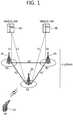
- FIG. 1 illustrates a wireless communication system to which the present invention is applied.
- the wireless communication system may also be referred to as an evolved-UMTS terrestrial radio access network (E-UTRAN) or a long term evolution (LTE)/LTE-A system.
- E-UTRAN evolved-UMTS terrestrial radio access network
- LTE long term evolution
- LTE-A long term evolution
- the E-UTRAN includes at least one base station (BS) 20 which provides a control plane and a user plane to a user equipment (UE) 10.
- the UE 10 may be fixed or mobile, and may be referred to as another terminology, such as a mobile station (MS), a user terminal (UT), a subscriber station (SS), a mobile terminal (MT), a wireless device, etc.
- the BS 20 is generally a fixed station that communicates with the UE 10 and may be referred to as another terminology, such as an evolved node-B (eNB), a base transceiver system (BTS), an access point, etc.
- eNB evolved node-B
- BTS base transceiver system
- access point etc.
- the BSs 20 are interconnected by means of an X2 interface.
- the BSs 20 are also connected by means of an S1 interface to an evolved packet core (EPC) 30, more specifically, to a mobility management entity (MME) through S1-MME and to a serving gateway (S-GW) through S1-U.
- EPC evolved packet core
- MME mobility management entity
- S-GW serving gateway
- the EPC 30 includes an MME, an S-GW, and a packet data network-gateway (P-GW).
- the MME has access information of the UE or capability information of the UE, and such information is generally used for mobility management of the UE.
- the S-GW is a gateway having an E-UTRAN as an end point.
- the P-GW is a gateway having a PDN as an end point.
- Layers of a radio interface protocol between the UE and the network can be classified into a first layer (L1), a second layer (L2), and a third layer (L3) based on the lower three layers of the open system interconnection (OSI) model that is well-known in the communication system.
- a physical (PHY) layer belonging to the first layer provides an information transfer service by using a physical channel
- a radio resource control (RRC) layer belonging to the third layer serves to control a radio resource between the UE and the network.
- the RRC layer exchanges an RRC message between the UE and the BS.
- FIG. 2 is a diagram illustrating a radio protocol architecture for a user plane.
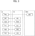
- FIG. 3 is a diagram illustrating a radio protocol architecture for a control plane.
- the user plane is a protocol stack for user data transmission.
- the control plane is a protocol stack for control signal transmission.
- a PHY layer provides an upper layer with an information transfer service through a physical channel.
- the PHY layer is connected to a medium access control (MAC) layer which is an upper layer of the PHY layer through a transport channel.
- MAC medium access control
- Data is transferred between the MAC layer and the PHY layer through the transport channel.
- the transport channel is classified according to how and with what characteristics data is transmitted through a radio interface.
- the physical channel is modulated using an orthogonal frequency division multiplexing (OFDM) scheme, and utilizes time and frequency as a radio resource.
- OFDM orthogonal frequency division multiplexing
- a function of the MAC layer includes mapping between a logical channel and a transport channel and multiplexing/de-multiplexing on a transport block provided to a physical channel over a transport channel of a MAC service data unit (SDU) belonging to the logical channel.
- the MAC layer provides a service to a radio link control (RLC) layer through the logical channel.
- RLC radio link control
- a function of the RLC layer includes RLC SDU concatenation, segmentation, and reassembly.
- QoS quality of service
- the RLC layer provides three operation modes, i.e., a transparent mode (TM), an unacknowledged mode (UM), and an acknowledged mode (AM).
- TM transparent mode
- UM unacknowledged mode
- AM acknowledged mode
- the AM RLC provides error correction by using an automatic repeat request (ARQ).
- ARQ automatic repeat request
- Functions of a packet data convergence protocol (PDCP) layer in the user plane include user data delivery, header compression, and ciphering.
- Functions of a PDCP layer in the control plane include control-plane data delivery and ciphering/integrity protection.
- PDCP packet data convergence protocol
- a radio resource control (RRC) layer is defined only in the control plane.
- the RRC layer serves to control the logical channel, the transport channel, and the physical channel in association with configuration, reconfiguration and release of radio bearers (RBs).
- An RB is a logical path provided by the first layer (i.e., PHY layer) and the second layer (i.e., MAC layer, RLC layer, and PDCP layer) for data delivery between the UE and the network.
- the configuration of the RB implies a process for specifying a radio protocol layer and channel properties to provide a specific service and for determining respective detailed parameters and operations.
- the RB can be classified into two types, i.e., a signaling RB (SRB) and a data RB (DRB).
- SRB signaling RB
- DRB data RB
- the SRB is used as a path for transmitting an RRC message in the control plane.
- the DRB is used as a path for transmitting user data in the user plane.
- the UE When an RRC connection exists between an RRC layer of the UE and an RRC layer of the network, the UE is in an RRC connected state, and otherwise the UE is in an RRC idle state.
- Data are transmitted from the network to the UE through a downlink transport channel.
- the downlink transport channel include a broadcast channel (BCH) for transmitting system information and a downlink-shared channel (SCH) for transmitting user traffic or control messages.
- BCH broadcast channel
- SCH downlink-shared channel
- the user traffic of downlink multicast or broadcast services or the control messages can be transmitted on the downlink-SCH or an additional downlink multicast channel (MCH).
- Data are transmitted from the UE to the network through an uplink transport channel.
- the uplink transport channel include a random access channel (RACH) for transmitting an initial control message and an uplink SCH for transmitting user traffic or control messages.
- RACH random access channel
- Examples of logical channels belonging to a higher channel of the transport channel and mapped onto the transport channels include a broadcast channel (BCCH), a paging control channel (PCCH), a common control channel (CCCH), a multicast control channel (MCCH), a multicast traffic channel (MTCH), etc.
- BCCH broadcast channel
- PCCH paging control channel
- CCCH common control channel
- MCCH multicast control channel
- MTCH multicast traffic channel
- the physical channel includes several symbols in a time domain and several sub-carriers in a frequency domain.
- One sub-frame includes a plurality of symbols in the time domain.
- One subframe includes a plurality of resource blocks.
- One resource block includes a plurality of symbols and a plurality of sub-carriers.
- each subframe may use specific sub-carriers of specific symbols (e.g., a first symbol) of a corresponding subframe for a physical downlink control channel (PDCCH), i.e., an L1/L2 control channel.
- a transmission time interval (TTI) is a unit time of data transmission, and is 1 millisecond (ms) which corresponds to one subframe.
- the RRC state indicates whether an RRC layer of the UE is logically connected to an RRC layer of an E-UTRAN. If the two layers are connected to each other, it is called an RRC connected state, and if the two layers are not connected to each other, it is called an RRC idle state.
- the UE When in the RRC connected state, the UE has an RRC connection and thus the E-UTRAN can recognize a presence of the UE in a cell unit. Accordingly, the UE can be effectively controlled.
- the UE when in the RRC idle state, the UE cannot be recognized by the E-UTRAN, and is managed by a core network in a tracking area unit which is a unit of a wider area than a cell. That is, regarding the UE in the RRC idle state, only a presence or absence of the UE is recognized in a wide area unit. To get a typical mobile communication service such as voice or data, a transition to the RRC connected state is necessary.
- the UE When a user initially powers on the UE, the UE first searches for a proper cell and thereafter stays in the RRC idle state in the cell. Only when there is a need to establish an RRC connection, the UE staying in the RRC idle state establishes the RRC connection with the E-UTRAN through an RRC connection procedure and then transitions to the RRC connected state. Examples of a case where the UE in the RRC idle state needs to establish the RRC connection are various, such as a case where uplink data transmission is necessary due to telephony attempt of the user or the like or a case where a response message is transmitted in response to a paging message received from the E-UTRAN.
- a non-access stratum (NAS) layer belongs to an upper layer of the RRC layer and serves to perform session management, mobility management, or the like.
- EMM-REGISTERED EPS mobility management-REGISTERED
- EMM-DEREGISTERED EMM-DEREGISTERED
- ECM EPS connection management
- ECM-CONNECTED ECM-CONNECTED
- the UE in the ECM-IDLE state performs a UE-based mobility related procedure such as cell selection or reselection without having to receive a command of the network.
- a UE-based mobility related procedure such as cell selection or reselection without having to receive a command of the network.
- mobility of the UE is managed by the command of the network. If a location of the UE in the ECM-IDLE state becomes different from a location known to the network, the UE reports the location of the UE to the network through a tracking area update procedure.
- the system information includes essential information that needs to be known to a UE to access a BS.
- the UE has to receive all system information before accessing the BS. Further, the UE always has to have the latest system information. Since the system information is information that must be known to all UEs in one cell, the BS periodically transmits the system information.
- the system information is classified into a master information block (MIB), a scheduled block (SB), and a system information block (SIB).
- MIB allows the UE to know a physical configuration (e.g., bandwidth) of a specific cell.
- the SB reports transmission information (e.g., a transmission period or the like) of SIBs.
- the SIB is a group of a plurality of pieces of system information related to each other. For example, an SIB includes only information of a neighboring cell, and another SIB includes only information of an uplink radio channel used by the UE.
- a service provided by the network to the UE can be classified into three types to be described below. Further, according to which service can be provided, the UE recognizes a cell type differently. A service type will be first described below, and then the cell type will be described.
- Limited service This service provides an emergency call and an earthquake and tsunami warning system (ETWS), and can be provided in an acceptable cell.
- ETWS earthquake and tsunami warning system
- Normal service This service denotes a public use service for general use, and can be provided in a suitable or normal cell.
- This service denotes a service for a network service provider, and a cell can be used only by the network service provider and cannot be used by a normal user.
- a service type provided by a cell can be identified as follows.
- the UE may perform procedures for selecting/reselecting a cell having suitable quality in order to receive a service.
- the UE in an RRC idle state needs to be ready to receive the service through the cell by selecting the cell having suitable quality all the time. For example, the UE that has been just turned on must select the cell having suitable quality so as to be registered into a network. If the UE that has stayed in an RRC connected state enters into the RRC idle state, the UE must select a cell on which the UE itself is camped. As such, a process of selecting a cell satisfying a certain condition by the UE in order to stay in a service waiting state such as the RRC idle state is called a cell selection.
- the cell selection is performed in a state that the UE does not currently determine a cell on which the UE itself is camped in the RRC idle state, and thus it is very important to select the cell as quickly as possible. Therefore, if a cell provides radio signal quality greater than or equal to a predetermined level, the cell may be selected in the cell selection process of the UE even though the cell is not a cell providing best radio signal quality.
- the UE searches for available PLMNs and selects a suitable PLMN to receive a service. Subsequently, the UE selects a cell having a signal quality and property capable of receiving a suitable service among the cells provided by the selected PLMN.
- the cell selection process can be classified into two processes.
- One process is an initial cell selection process, and in this process, the UE does not have previous information on radio channels. Therefore, the UE searches for all radio channels to find a suitable cell. In each channel, the UE searches for the strongest cell. Subsequently, if a suitable cell satisfying cell selection criteria is found, the UE selects the cell.
- the signal strength and quality between the UE and the BS may be changed due to the change of the UE mobility and wireless environment. Therefore, if the quality of the selected cell deteriorates, the UE may select another cell providing better quality. If a cell is reselected in this manner, a cell providing signal quality better than that of the currently selected cell is selected in general. This process is called a cell reselection.
- a basic purpose of the cell reselection process is generally to select a cell providing best quality to the UE from the perspective of the radio signal quality.
- the network may notify the UE of a priority determined for each frequency.
- the UE that has received the priority may consider this priority more preferentially than the radio signal quality criteria during the cell reselection process.
- a method of selecting or reselecting a cell based on the signal property of the wireless environment there may be cell reselection methods as described below, based on the RAT and frequency characteristics of the cell.
- the UE measures quality of a serving cell and a neighboring cell for a cell reselection.
- the cell reselection is performed based on cell reselection criteria.
- the cell reselection criteria have following characteristics with regard to the measurement of serving cells and neighboring cells.
- the intra-frequency cell reselection is basically based on ranking.
- the ranking is an operation for defining a criterion value for evaluation of the cell reselection and for ordering cells according to a magnitude of the criterion value by using the criterion value.
- a cell having the highest criterion is referred to as a best-ranked cell.
- the cell criterion value is a value to which a frequency offset or a cell offset is optionally applied on the basis of a value measured by the UE for a corresponding cell.
- the inter-frequency cell reselection is based on a frequency priority provided by the network.
- the UE attempts to camp on at a frequency having a top priority.
- the network may provide the same frequency priority to be commonly applied to UEs in a cell by using broadcast signaling or may provide a frequency-specific priority to each UE by using dedicated signaling for each UE.
- the network may provide parameters (e.g., frequency-specific offsets) for use in cell reselection to the UE for each frequency.
- the network may provide a neighboring cell list (NCL) for use in the cell reselection to the UE.
- NCL includes cell-specific parameters (e.g. cell-specific offsets) used in the cell reselection.
- the network may provide the UE with a black list, i.e., a list of cells not to be selected in the cell reselection.
- the UE does not perform the cell reselection on cells included in the black list.
- a ranking criterion used to assign a priority to a cell is defined by Equation 1 below.
- Rs Qmeas , s + Qhyst
- Rn Qmeas , n ⁇ Qoffset
- Rs denotes a ranking value of a serving cell
- Rn denotes a ranking criterion of a neighboring cell
- Qmeas,s denotes a quality value measured for the serving cell by the UE
- Qmeas,n denotes a quality value measured for the neighboring cell by the UE
- Qhyst denotes a hysteresis value for ranking
- Qoffset denotes an offset between two cells.
- the ranking criterion Rs of the serving cell and the ranking criterion Rn of the neighboring cell are not much different from each other and constantly vary, ranking orders of the serving cell and the neighboring cell may change frequently.
- the serving cell and the neighboring cell may be reselected alternately while changing their ranking orders frequently.
- the hysteresis value Qhyst is used to give a hysteresis in the cell reselection.
- the UE measures the ranking criterion Rs of the serving cell and the ranking criterion Rn of the neighboring cell according to the above equation.
- a cell having the greatest ranking criterion value is reselected by considering this cell as a best-ranked cell.
- the quality of cells is considered as a most important factor when performing the cell reselection. If a reselected cell is not a suitable cell, the UE excludes the reselected cell or a frequency of the reselected cell from targets of the cell reselection.
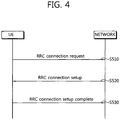
- FIG. 4 is a flowchart showing an RRC connection establishment procedure.
- a UE sends to a network an RRC connection request message for requesting an RRC connection (step S510).
- the network sends an RRC connection setup message in response to the RRC connection request (step S520). After receiving the RRC connection setup message, the UE enters an RRC connection mode.
- the UE sends to the network an RRC connection setup complete message used to confirm successful completion of the RRC connection establishment (step S530).
- RRC connection reestablishment is also performed like the RRC connection setup.
- the RRC connection reestablishment is to reestablish RRC connection and is related to the restart of an SRB1 operation, the reactivation of security, and the configuration of a Primary Cell (PCell).
- the UE sends an RRC connection reestablishment request message that requests RRC connection reestablishment.
- the network sends an RRC connection reestablishment message.
- the UE sends an RRC connection reestablishment complete message.
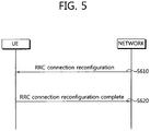
- FIG. 5 is a flowchart showing an RRC connection reconfiguration procedure.
- An RRC connection reconfiguration is used to modify an RRC connection. This is used to establish/modify/release an RB, to perform a handover, and to set up/modify/release a measurement.
- the network sends an RRC connection reconfiguration message for modifying RRC connection to the UE (S610).
- the UE sends an RRC connection reconfiguration complete message, used to check whether the RRC connection reconfiguration has been successfully completed, to the network (S620).
- FIG. 6 is a flowchart illustrating a process of reporting UE information.
- the network sends a UE information request message for obtaining UE information to the UE (S710).
- the UE information request message includes a field indicating whether the UE reports information about a random access process and/or a radio link failure or not.
- the UE information request message includes a field indicating whether the UE reports logged measurement or not.
- the UE sends a UE information response message, including information requested by the UE information request, to the network (S720).
- the UE persistently measures quality of a serving cell providing a current service and quality of a neighboring cell.
- the UE reports a measurement result to a network at a proper time.
- the network provides optimal mobility to the UE by using a handover or the like.
- the UE may perform measurement with a specific purpose determined by the network, and may report the measurement result to the network. For example, the UE receives broadcast information of a specific cell determined by the network. The UE may report to a serving cell a cell identify (also referred to as a global cell identity) of the specific cell, location identification information indicating a location of the specific cell (e.g., a tracking area code), and/or other cell information (e.g., whether it is a member of a closed subscriber group (CSG) cell).
- a cell identify also referred to as a global cell identity
- location identification information indicating a location of the specific cell
- CSG closed subscriber group
- the UE may report a measurement result and location information on cells with bad quality to the network.
- the network may attempt to optimize the network on the basis of the measurement result reported from UEs which assist the network operation.
- the UE In a mobile communication system having a frequency reuse factor of 1, mobility is generally supported between different cells existing in the same frequency band. Therefore, in order to properly guarantee the UE mobility, the UE has to properly measure cell information and quality of neighboring cells having the same center frequency as a center frequency of a serving cell. Measurement on a cell having the same center frequency as the center frequency of the serving cell is referred to as intra-frequency measurement. The UE performs the intra-frequency measurement and reports a measurement result to the network, so as to achieve the purpose of the measurement result.
- a mobile communication service provider may perform a network operation by using a plurality of frequency bands. If a service of a communication system is provided by using the plurality of frequency bands, optimal mobility can be guaranteed to the UE when the UE is able to properly measure cell information and quality of neighboring cells having a different center frequency from the center frequency of the serving cell. Measurement on a cell having the different center frequency from the center frequency of the serving cell is referred to as inter-frequency measurement. The UE has to be able to perform the inter-frequency measurement and report a measurement result to the network.
- RAT may include a GMS EDGE radio access network (GERAN) and a UMTS terrestrial radio access network (UTRAN) conforming to the 3GPP standard, and may also include a CDMA 200 system conforming to the 3GPP2 standard.
- GMS EDGE radio access network GERAN
- UTRAN UMTS terrestrial radio access network
- FIG. 7 is a flowchart illustrating the existing method of performing measurement.
- a UE receives measurement configuration information from a BS (step S810).
- a message including the measurement configuration information is referred to as a measurement configuration message.
- the UE performs measurement based on the measurement configuration information (step S820). If a measurement result satisfies a reporting condition included in the measurement configuration information, the UE reports the measurement result to the BS (step S830).
- a message including the measurement result is referred to as a measurement report message.
- the measurement configuration information may include the following information.
- UE has a measurement object list, a measurement report configuration list, and a measurement ID list in order perform a measurement procedure.
- the BS can assign only one measurement object to the UE with respect to one frequency.
- Events for triggering measurement reporting shown in the table below are defined in the section 5.5.4 of 3GPP TS 36.331 V8.5.0 (2009-03 ) "Evolved Universal Terrestrial Radio Access (E-UTRA) Radio Resource Control (RRC); Protocol specification (Release 8)".
- Table 1 EVENT REPORT CONDITION Event A1 Serving becomes better than threshold Event A2 Serving becomes worse than threshold Event A3 Neighbour becomes offset better than serving Event A4 Neighbour becomes better than threshold Event A5 Serving becomes worse than threshold1 and neighbour becomes better than threshold2
- Event B2 Serving becomes worse than threshold1 and inter RAT neighbour becomes better than threshold2
- the UE If the measurement result of the UE satisfies the determined event, the UE transmits a measurement report message to the BS.
- FIG. 8 shows an example of a measurement configuration assigned to a UE.
- a measurement identity1 801 associates an intra-frequency measurement object with a reporting configuration 1.
- the UE performs intra-frequency measurement.
- the reporting configuration 1 is used to determine a reporting type and a criterion for reporting a measurement result.
- a measurement identity2 802 is associated with the intra-frequency measurement object similarly to the measurement identifier1 801, and associates the intra-frequency measurement object with a reporting configuration 2.
- the UE performs intra-frequency measurement.
- the reporting configuration 2 is used to determine a reporting format and a criterion for reporting a measurement result.
- the UE transmits a measurement result even if the measurement result on the intra-frequency measurement object satisfies any one of the reporting configuration 1 and the reporting configuration 2.
- a measurement identity3 803 associates an inter-frequency measurement object 1 with a reporting configuration 3.
- the UE reports the measurement result.
- measurement identity4 804 associates an inter-frequency measurement object 2 with the reporting configuration 2.
- the UE reports the measurement result.
- the BS may transmit to the UE a new measurement configuration message or a measurement configuration modification message.
- FIG. 9 shows an example of deleting a measurement identity.
- a measurement identity2 802 is deleted, measurement on a measurement object associated with the measurement identity2 802 is suspended, and a measurement report is not transmitted.
- a reporting configuration or a measurement object associated with the deleted measurement identity may not be modified.
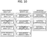
- FIG. 10 shows an example of deleting a measurement object.
- a UE When an inter-frequency measurement object 1 is deleted, a UE also deletes an associated measurement identifier3 803. Measurement on the inter-frequency measurement object 1 is suspended, and a measurement report is not transmitted. However, a reporting configuration associated with the deleted inter-frequency measurement object 1 may not be modified or deleted.
- the UE When the reporting configuration is deleted, the UE also deletes an associated measurement identifier. The UE suspends measurement on an associated measurement object according to the associated measurement identifier. Measurement on the measurement object and measurement reporting are suspended. However, a measurement object associated with the deleted reporting configuration may not be modified or deleted.
- UE After receiving a measurement configuration, UE performs measurement for a measurement object associated with a measurement ID. In relation to a result of the measurement, the UE evaluates whether the result satisfies a measurement report condition based on a report configuration included in the measurement configuration. If a report criterion included in the report configuration is satisfied, the UE sends a measurement report message, including measurement report information, to a network.
- the measurement report message includes the following pieces of information.
- Measurement ID a measurement ID associated with a report configuration that satisfies a report criterion.
- a network can know that a measurement report received from UE has been transmitted according to what criterion by using the measurement ID.
- the quality value of a measured serving cell the quality value of a serving cell that has been measured by UE.
- the information includes the ID of a neighboring cell and the quality value of the neighboring cell.
- the ID of the neighboring cell is a physical cell identifier of the neighboring cell that satisfies a report criterion.
- the quality value of the neighboring cell is the quality value of the neighboring cell that satisfies the report criterion.
- MDT Minimization of Driving Test
- the MDT is a test in which service providers perform tests using terminals for coverage optimization instead of using vehicles. Coverage is changed depending on the position of a base station, the deployment of surrounding buildings, and use environments of users. Accordingly, a service provider needs to perform a driving test periodically, and thus lots of costs and resources are consumed.
- the MDT is a test in which a service provider measures coverage using terminals.
- the MDT may be divided into a logged MDT and an immediate MDT.
- a terminal performs MDT measurement and then transfers logged measurement to a network at a specific point of time.
- a terminal performs MDT measurement and transfers the measurement to a network when a report condition is satisfied.
- MDT measurement is performed in RRC idle mode, but in the immediate MDT, MDT measurement is performed in RRC connected mode.
- FIG. 11 shows a process of performing the MDT.
- the MDT is performed in order of an MDT configuration 1010, MDT measurement 1020, and an MDT report 1030.
- the MDT configuration may be transmitted from a network to UE through a logged measurement configuration message, that is, an RRC message.
- the UE may receive the MDT configuration in RRC connected mode. Although RRC mode switches to RRC idle mode, the MDT configuration remains intact, and thus an MDT measurement result is also maintained.
- the MDT configuration may include at least one of a logging interval, a reference time, and an area configuration.
- the logging interval indicates an interval where a result of measurement is stored.
- the reference time is used to inform a reference time when UE sends logged measurement.
- the area configuration refers to an area that is requested for UE to perform logging in the area.
- UE performs MDT measurement based on the MDT configuration. For example, UE performs MDT measurement at a logging interval within the MDT configuration.
- RSRP Reference Signal Received Power
- RSRQ Reference Signal Received Quality
- RSCP Received Signal Code Power
- Ec/No which are well known to those skilled in the art may be used as a measurement value.
- UE sends logged measurement to a network in RRC connected mode.
- logged MDT UE logs on to measurement in RRC idle mode. Furthermore, the UE that has entered RRC connected mode sends logged measurement to the network again.
- the logged measurement may include at least one of a result of measurement for an available serving cell, a result of measurement for an available neighbour cell, and time information and location information.
- the UE information report process of FIG. 6 may be used.
- a network sends an information request, including a field indicating a report on logged measurement, to UE.
- the UE sends an information response, including the logged measurement, to the network.
- a service provider may synthesize MDT measurements received from several UEs, make a coverage map indicating whether service is possible over the entire area where the service provider provides the service and a distribution of the quality of the service, and use the coverage map in the operation and optimization of a network. For example, when a report on the coverage problem of a specific area is received from UE, a service provider may extend the coverage of the corresponding area cell by increasing the transmit power of a BS which provides service to the corresponding area.
- a network may transfer an MDT measurement configuration to the UE when the UE is in RRC connected mode.
- An MDT measurement configuration optimized for one cell may differ from an MDT measurement configuration optimized for the other cell. If UE in RRC idle mode does not set up RRC connection with a new cell and continues to remain in RRC idle mode, a network cannot transfer an MDT measurement configuration optimized for the new cell to the UE.
- a broadcast message may be used.
- the broadcast message is information that is received by all UEs within a cell. Since all the UEs do not need to perform MDT measurement, a method regarding how UE will apply a broadcasted MDT measurement configuration selectively is also required.
- UE receives a measurement configuration for MDT measurement and a parameter that will be used to determine whether the measurement configuration will be applied or not from a network.
- the UE determines whether or not to apply the measurement configuration based on the received parameter.
- the parameter may be broadcast information.
- FIG. 12 is a flowchart illustrating a method of performing measurement according to an embodiment of the present invention.
- the UE in RRC idle mode receives a UE selection parameter from a network (S1210).
- the UE selection parameter is information indicating whether UE will apply a measurement configuration or not.
- the UE selection parameter may be broadcast information that is received by all UEs within a cell.
- the UE receives a measurement configuration from the network (S1220).
- the measurement configuration may be an MDT configuration for MDT measurement.
- the MDT configuration may include at least one of a logging interval, a reference time, and an area configuration.
- the measurement configuration may be broadcast information that is received by all UEs within a cell.
- the measurement configuration may be transmitted along with or separately from the UE selection parameter.
- the measurement configuration may include the value of a validity timer.
- the validity timer indicates the lifetime of the measurement configuration. If the measurement configuration is an MDT configuration, the value of the validity timer may be said to be logging duration.
- the UE determines whether or not to apply the measurement configuration based on the UE selection parameter. If the UE determines to apply the measurement configuration based on the UE selection parameter, the validity timer is started (S1230).
- the UE in RRC idle mode logs measurement based on the measurement configuration (S1240).
- the measurement configuration is updated into a new measurement configuration and the validity timer may be restarted. Furthermore, the logged measurement may be discarded according to the previously configured measurement configuration.
- the UE discards the measurement configuration. This means that the UE removes the measurement configuration and stops measurement.
- the validity timer expires, not only the measurement configuration, but also the logged measurement may be discarded.
- the measurement configuration may be discarded, but the logged measurement may remain intact.
- the logged measurement may be maintained for a specific time after the validity timer expires.
- the UE establishes or reestablishes RRC connection with a BS and enters RRC connected mode (S1250). If the validity timer expires before entering RRC connected mode, the UE discards the measurement configuration and maintains the logged measurement. The UE removes the measurement configuration and no longer performs measurement. Alternatively, when the UE enters RRC connected mode, the validity timer may be operating.
- the UE When the UE switches from RRC idle mode to RRC connected mode, the UE sends a logging indicator to the network (S1260).
- the logging indicator may be an indicator that indicates the availability of logged measurement.
- the UE performs measurement in RRC idle mode and, when entering RRC connected mode, informs the network whether there is logged measurement.
- the UE may inform the network whether it is the last occasion that an MDT log may be reported.
- the validity timer expires and thus the MDT configuration is discarded, but a new MDT configuration is not updated, the UE may inform the network that there is a managed MDT log and the MDT log will be soon discarded. This may be informed using logging indicators of 2 bits as in the table below.
- the UE may send the logging indicator to the network when RRC connection is established, the RRC connection is reestablished, or the RRC connection is reconfigured.
- the logging indicator may be included in an RRC connection setup complete message.
- the RRC connection reconfiguration process of FIG. 5 the logging indicator may be included in the RRC connection reconfiguration complete message.
- the network which has known that there is logged measurement based on the logging indicator sends an information request, requesting a report on the logged measurement, to the UE (S1270).
- the UE sends an information response, including the logged measurement, to the network (S1280).
- Table 3 WHEN UE OPERATION Timer start When the measurement configuration and/or the UE selection parameter are receive or the measurement configuration is applied Start measurement using the measurement configuration Timer stop When a UE buffer is full, the measurement configuration is invalid, or RRC connected mode is entered Measurement is stopped Timer expire The measurement configuration is discarded, measurement is stopped, and logged measurement is maintained for a specific time
- the UE selection parameter is described in detail below.
- UE uses the UE selection parameter in order to determine whether it will participate in requested measurement or not.
- the UE selection parameter may include a UE identifier or a UE identifier.
- the UE selection parameter may include a threshold. For example, UE may generate a random number and compare the random number with the threshold. If the random number is greater than the threshold, the UE applies a measurement configuration.
- the UE selection parameter may include information for generating the random number.
- the UE may determine whether or not to apply a measurement configuration by combining the UE selection parameter and a predefined parameter.
- the predefined parameter may include at least one of negotiations with a BS regarding whether UE will participate in measurement (this may correspond to the case where the UE expresses an intention to voluntarily participate in measurement to the BS), whether MDT is supported, and information previously received from a network.
- the UE selection parameter may indicate a UE group.
- UEs within a cell are classified into one or more groups.
- the groups may perform measurement in exclusive time/frequencies periodically.
- a cell that sends a UE selection parameter and a measurement configuration may be changed.
- the validity of a UE selection parameter according to a change of a cell is described below.
- FIG. 13 is a flowchart illustrating a method of performing measurement according to an embodiment of the present invention.
- the UE in RRC idle mode receives a first UE selection parameter from a cell 1 (S1310).
- the UE receives a first measurement configuration from the cell 1 (S1320). If the UE selects to apply the measurement configuration based on the UE selection parameter, the validity timer is started (S1330). While the validity timer operates, the UE in RRC idle mode performs logging measurement based on the measurement configuration (S1340).
- the UE receives a second UE selection parameter from a cell 2 (S1350).
- the UE receives a second measurement configuration from the cell 2 (S1360). If there is a measurement configuration already applied by the UE, the UE ignores the second UE selection parameter and/or the second measurement configuration (S1370).
- a measurement configuration received from other cell is not applied.
- the UE has the first measurement configuration, but may not have the first UE selection parameter.
- the UE determines whether or not to apply the measurement configuration based on the second UE selection parameter. If the UE selects to apply the measurement configuration, the UE may apply the first measurement configuration that has been previously applied, not the second measurement configuration.
- the UE has the first UE selection parameter, but may not have the first measurement configuration.
- the UE determines whether or not to apply the measurement configuration based on the second UE selection parameter. If the UE selects to apply the measurement configuration, the UE may apply the second measurement configuration.
- the UE selection parameter is valid until the UE receives a new UE selection parameter from a new cell.
- the UE may determine whether or not to apply the measurement configuration based on the second UE selection parameter.
- a BS may send an indicator, informing whether the UE selection parameter will be ignored or not, to the UE.
- the UE may store a plurality of measurement configurations.
- the UE may inform the BS of information about the corresponding measurement configuration.
- the BS may determine that the logged measurement transmitted by the UE is based on what measurement configuration on the basis of information about the measurement configuration and the result of the logged measurement which have been received from the UE.
- a network may instruct specific UE of each cell to perform the execution of measurement and a report which are necessary for a specific number of UEs statistically. Whether the UE will perform the execution of measurement and the report or not is determined by a statistics or probability method. Thus, the case where specific UE performs measurement repeatedly or excessively can be prevented.
- each cell can instruct a measurement configuration suitable for the cell to UE
- UE in RRC idle mode can perform measurement a unique measurement configuration that is broadcasted by a new cell.
- a measurement configuration and measurement report which are optimized for each cell are possible.
- an RRC connection reconfiguration message is a message for changing the RRC configuration of UE in RRC connected mode.
- An RRC connection release message switches the UE in RRC connected mode to UE in RRC idle mode and changes an RRC configuration related to cell reselection which is performed in RRC idle mode.
- MDT measurement is measurement in RRC idle mode.
- a network may need to utilize a smooth measurement configuration structure in RRC connected mode.
- UE may need to use the same measurement configuration irrespective of RRC connected mode and RRC idle mode.
- a network provides UE with RRC mode indicator indicating RRC mode to which an RRC configuration has to be applied.
- the UE applies the RRC configuration in the instructed RRC mode.
- the RRC configuration may include the measurement configuration of UE.
- the RRC configuration may be a measurement configuration for MDT.
- the RRC mode indicator may be represented by any one of IDLE, CONNECTED, and BOTH. 'IDLE' indicates RRC idle mode, 'CONNECTED' indicates RRC connected mode, and 'BOTH' indicates both RRC idle mode and RRC connected mode.
- An RRC configuration associated with RRC mode indicator may be part of or the entire RRC configuration including RRC mode indicator.
- An RRC mode indicator may be included in an RRC configuration message. For example, if an RRC configuration is a measurement configuration, RRC mode indicator may be included in a measurement configuration message.
- RRC mode indicator may be included in an actually associated part of the RRC configuration. For example, it is assumed that RRC mode is associated with a specific frequency of a measurement configuration.
- a measurement configuration may be configured so that RRC mode indicator is associated with a measurement object or a measurement ID.
- 'MeasIdToAddModList' is an Information Element (IE) used to add or modify a measurement object in 3GPP TS 36.331.
- An RRC mode indicator may be added to MeasIdToAddModList as follows.
- RRC mode indicator indicates 'IDLE'
- UE applies an RRC configuration to only RRC idle mode. It may correspond to that the RRC configuration is valid only in RRC idle mode.
- RRC mode indicator indicates 'CONNECTED'
- UE applies an RRC configuration to only RRC connected mode. It may correspond to that the RRC configuration is valid only in RRC connected mode.
- RRC mode indicator indicates 'BOTH'
- UE applies an RRC configuration to RRC connected mode and RRC idle mode. It may correspond to that the RRC configuration is valid in RRC connected mode and in RRC idle mode.
- UE may maintain the RRC configuration although RRC mode is changed. If RRC mode indicator indicates 'IDLE' or 'BOTH', UE may maintain an associated RRC configuration although RRC connected mode is switched to RRC idle mode. The UE may also maintain results (e.g., a result of logged measurement) generated by the RRC configuration.
- RRC mode indicator indicates 'IDLE' or 'BOTH'
- UE maintains results generated by the RRC configuration although RRC mode is changed.
- RRC mode indicator indicates 'IDLE' or 'BOTH'
- UE discards the RRC configuration when RRC connected mode switches to RRC idle mode, but maintains the results generated by the RRC configuration.
- RRC mode indicator indicates 'BOTH'
- UE in RRC idle mode may generate results by applying a corresponding RRC configuration.
- the UE may report RRC mode indicator, the RRC configuration and/or the results to a BS.
- the BS which has known that the UE applies the RRC configuration indicated by 'BOTH' may configure a similar or identical RRC configuration for the UE so that the corresponding RRC configuration remains intact.
- FIG. 14 is a flowchart illustrating a method of performing measurement according to another embodiment of the present invention. It is assumed that there are a serving cell of a frequency f1 of, a neighboring cell of a frequency f1, and a neighboring cell of a frequency f2.
- the UE receives a measurement configuration from the serving cell (S1410).
- the measurement configuration includes a measurement configuration regarding the frequency f1 and the frequency f1.
- the measurement configuration further includes RRC mode indicator indicating that the measurement configuration of the frequency f2 is applied to RRC idle mode.
- the UE performs measurement for the cells of the frequency f1 in RRC connected mode (S1420). That is, the UE measures the serving cell of the frequency f1 (S1421) and measures the neighboring cell of the frequency f1 (S1422).
- the UE reports a result of the measurement (S1430).
- the UE switches to RRC idle mode (S1440).
- the UE deletes the measurement configuration of the frequency f1, but maintains the measurement configuration of the frequency f2.
- the UE performs measurement for the cells of the frequency f2 in RRC idle mode (S1450).
- the UE measures the serving cell of the frequency f1 (S1451) and measures the neighboring cell of the frequency f2 (S1452).
- the UE switches to RRC connected mode (S1460). Although the UE switches to RRC connected mode, the UE maintains a result of the measurement according to the measurement configuration of the frequency f2.
- the UE reports a result of the measurement, performed according to the measurement configuration of the frequency f2, to the BS (S1470).
- the UE may report a result of the measurement, performed according to the measurement configuration of the frequency f2, to a BS at the request of the BS.
- the UE switches to RRC idle mode, the UE maintains a result of the measurement for the frequency f2 that has not been reported.
- FIG. 15 is a flowchart illustrating a method of performing measurement according to yet another embodiment of the present invention.
- the UE receives a measurement configuration from a serving cell (S1510).
- the measurement configuration includes a frequency f1 and a measurement configuration regarding the frequency f1.
- the measurement configuration further includes RRC mode indicator indicating that the measurement configuration of a frequency f2 is applied to RRC idle mode and RRC connected mode.
- the UE performs measurement for the cells of the frequencies f2 and f2 in RRC connected mode (S1520). That is, the UE measures the serving cell of the frequency f1 (S1521), measures the neighbour cell of the frequency f1 (S1522), and measures the neighboring cell of the frequency f2 (S1523).
- the UE reports a result of the measurement (S1530).
- the UE reports a result of the measurement (S1535).
- the UE switches to RRC idle mode (S1540).
- the UE deletes the measurement configuration of the frequency f1, but maintains the measurement configuration of the frequency f2.
- the UE performs measurement for the cells of the frequency f2 in RRC idle mode (S1550).
- the UE measures the serving cell of the frequency f1 (S1551) and measures the neighboring cell of the frequency f2 (S1552).
- the UE switches to RRC connected mode (S1560). Although the UE switches to RRC connected mode, the UE maintains a result of the measurement according to the measurement configuration of the frequency f2.
- the UE reports a result of the measurement, performed according to the measurement configuration of the frequency f2, to the BS (S1570).
- the UE may report a result of the measurement, performed according to the measurement configuration of the frequency f2, to a BS at the request of the BS.
- the UE may inform the BS of RRC mode indicator that has been designated as 'BOTH'. Accordingly, the BS can know that a result of the measurement of the frequency f2 is a result of the measurement in RRC idle mode and RRC connected mode.
- Each of entries within a result of the measurement transmitted by the UE may include an indicator indicating that measurement has been performed in which RRC mode.
- the serving cell which has received RRC mode indicator designated as 'BOTH' from the UE may intentionally avoid the reconfiguration of the measurement configuration regarding the frequency f2 so that the measurement configuration regarding the frequency f2 of the UE remains intact or may send RRC mode indicator indicating 'BOTH', together with a measurement configuration having the same configuration as the UE, to the UE (S1580).
- the UE may maintain a result of the measurement for the frequency f2 that has not been reported.
- a network may designate RRC mode to which a corresponding RRC configuration will be applied when configuring or reconfiguring the RRC configuration of UE.
- a network may designate whether UE has to measure which frequency in RRC idle mode particularly by utilizing the structure of a measurement configuration used in RRC connected mode. Additional measurement configuration signaling for changing a measurement configuration in RRC idle mode from a viewpoint of UE can be reduced, and a smooth measurement configuration in RRC connected mode can also be applied to RRC idle mode.
- a configuration may be performed so that UE measures a specific frequency both in RRC connected mode and RRC idle mode.
- a BS When reporting a result of measurement for an RRC configuration both in RRC idle mode and RRC connected mode, a BS may be informed of an RRC mode indicator.
- the BS may guarantee the continuity of the RRC configuration.
- the continuity of the RRC configuration may be usefully used for a specific purpose, such as MDT measurement.
- FIG. 16 is a block diagram of a wireless communication system in which the embodiments of the present invention are implemented.
- a BS 50 includes a processor 51, memory 52, and a Radio Frequency (RF) unit 53.
- the memory 52 is connected to the processor 51, and it stores various pieces of information for driving the processor 51.
- the RF unit 53 is connected to the processor 51, and it transmits and/or receives radio signals.
- the processor 51 embodies the proposed functions, processes and/or methods. In the embodiments of FIGS. 12 to 15 , the operation of the BS 50 may be embodied by the processor 51.
- the UE 60 includes a processor 61, memory 62, and an RF unit 63.
- the memory 62 is connected to the processor 61, and it stores various pieces of information for driving the processor 61.
- the RF unit 63 is connected to the processor 61, and it transmits and/or receives radio signals.
- the processor 61 embodies the proposed functions, processes and/or methods. In the embodiments of FIGS. 12 to 15 , the operation of the UE 60 may be embodied by the processor 61.
- the processor may include Application-Specific Integrated Circuits (ASICs), other chipsets, logic circuits, and/or data processors.
- the memory may include Read-Only Memory (ROM), Random Access Memory (RAM), flash memory, memory cards, storage media and/or other storage devices.
- the RF unit may include a baseband circuit for processing radio signals.
- the above-described scheme may be implemented using a module (process or function) configured to perform the above function.
- the module may be stored in the memory and executed by the processor.
- the memory may be placed inside or outside the processor and connected to the processor using a variety of well-known means.
Landscapes
- Engineering & Computer Science (AREA)
- Computer Networks & Wireless Communication (AREA)
- Signal Processing (AREA)
- Mobile Radio Communication Systems (AREA)
Claims (7)
- Procédé de procéder à une mesure consignée dans un système de communication sans fil, le procédé consistant à :recevoir par un équipement utilisateur, UE (10, 60) une configuration de minimisation de essais de conduites, MDT, pour la mesure MDT à partir d'une station de base, BS, (20, 50),le configuration MDT étant reçue avec un paramètre de sélection d'UE par l'intermédiaire d'un message de gestion des ressources radio, RRC,le paramètre de sélection d'UE comprenant un identifiant d'un groupe d'UE auquel la configuration MDT sera appliquée ;déterminer, par l'UE, si il faut appliquer ou non la configuration MDT sur la base du paramètre de sélection d'UE ;démarrer un temporisateur de validité s'il est déterminé qu'il faut appliquer la configuration MDT ;consigner, par l'UE, une mesure sur la base de la configuration MDT s'il est déterminer qu'il faut appliquer la configuration MDT,pendant le fonctionnement du temporisateur de validité, l'UE dans le mode inactif de RRC consigne une mesure sur la base de la configuration MDT pour collecter la mesure consignée, etlorsque le temporisateur de validité expire, la mesure consignée est conservée tandis que la configuration MDT est supprimée ;entrer, par l'UE, dans un mode connecté de RRC ; etenvoyer, par l'UE dans le mode connecté de RRC, un indicateur de consigne indiquant une disponibilité pour signaler la mesure consignée à la BS,l'indicateur de consigne étant compris dans le message complet d'établissement de RRC.
- Procédé selon la revendication 1, l'UE fonctionne dans un mode inactif de la gestion des ressources radio, RRC.
- Procédé selon la revendication 1 comprenant en outre les étapes :l'UE reçoit une demande d'informations, demandant la mesure consignée, provenant de la BS ; etl'UE envoyant une réponse d'informations, envoie la mesure consignée, à la BS.
- Procédé selon la revendication 1, le paramètre de sélection d'UE étant diffusé à partir de la BS.
- Procédé selon la revendication 4, la configuration de mesure étant diffusée à partir de la BS.
- Appareil (51, 61) destiné à procéder à la mesure consignée dans un système de communication sans fil,
une unité de radiofréquence, RF, (53, 63) qui transmet et reçoit des signaux radio ;
et
un processeur (51, 61) connecté à l'unité RF, le processeur étant configuré pour :recevoir une configuration de minimisation des essais de conduite, MDT, pour la mesure MDT à partir d'une station de base (20, 50),la configuration MDT étant reçue avec un paramètre de sélection d'UE par l'intermédiaire d'un message de gestion des ressources radio, RRC,le paramètre de sélection d'UE comprenant un identifiant d'un groupe d'UE auquel la configuration MDT sera appliquée ;déterminer s'il faut appliquer ou non la configuration MDT sur la base du paramètre de sélection d'UE ;démarrer un temporisateur de validité s'il est déterminé qu'il faut appliquer la configuration MDT ;consigner une mesure sur la base de la configuration MDT s'il est déterminé qu'il faut appliquer la configuration MDT,pendant le fonctionnement du temporisateur de validité, l'UE dans le mode inactif de la RRC consigne une mesure sur la base de la configuration MDT pour collecter une mesure consignée, etlorsque le temporisateur de validité expire, la mesure consignée étant conservée tandis que la configuration MDT est supprimée ;entrer en mode connecté de RRC ; etenvoyer un indicateur de consigne indiquant une disponibilité pour signaler la mesure consignée à la BS,l'indicateur de consigne étant compris dans un message complet d'établissement de RRC. - Appareil selon la revendication 6, le processeur étant configuré pour fonctionner en mode inactif de la gestion des ressources radio, RRC.
Applications Claiming Priority (2)
| Application Number | Priority Date | Filing Date | Title |
|---|---|---|---|
| US31725010P | 2010-03-24 | 2010-03-24 | |
| PCT/KR2011/002042 WO2011118998A2 (fr) | 2010-03-24 | 2011-03-24 | Procédé et appareil permettant d'exécuter une mesure enregistrée dans un système de communication sans fil |
Publications (3)
| Publication Number | Publication Date |
|---|---|
| EP2552149A2 EP2552149A2 (fr) | 2013-01-30 |
| EP2552149A4 EP2552149A4 (fr) | 2017-01-11 |
| EP2552149B1 true EP2552149B1 (fr) | 2019-08-14 |
Family
ID=44673771
Family Applications (1)
| Application Number | Title | Priority Date | Filing Date |
|---|---|---|---|
| EP11759747.6A Active EP2552149B1 (fr) | 2010-03-24 | 2011-03-24 | Procédé et appareil permettant d'exécuter une mesure enregistrée dans un système de communication sans fil |
Country Status (3)
| Country | Link |
|---|---|
| US (1) | US9137697B2 (fr) |
| EP (1) | EP2552149B1 (fr) |
| WO (1) | WO2011118998A2 (fr) |
Families Citing this family (30)
| Publication number | Priority date | Publication date | Assignee | Title |
|---|---|---|---|---|
| KR101676045B1 (ko) * | 2010-02-09 | 2016-11-15 | 엘지전자 주식회사 | 무선 통신 시스템에서 로그된 측정 폐기 방법 및 장치 |
| JP5094910B2 (ja) * | 2010-04-30 | 2012-12-12 | 株式会社エヌ・ティ・ティ・ドコモ | 移動通信システム及び移動局 |
| JP5068842B2 (ja) | 2010-04-30 | 2012-11-07 | 株式会社エヌ・ティ・ティ・ドコモ | 移動通信システムにおけるユーザ装置及び方法 |
| CN102484809A (zh) * | 2010-08-13 | 2012-05-30 | 京瓷株式会社 | 无线测量采集方法和无线终端 |
| WO2012023733A2 (fr) * | 2010-08-16 | 2012-02-23 | 엘지전자 주식회사 | Procédé destiné à permettre à un terminal de signaler un résultat de mesure pour un mdt à une station de base dans un système de communication sans fil et dispositif associé |
| EP3249996A1 (fr) | 2011-04-01 | 2017-11-29 | InterDigital Patent Holdings, Inc. | Procédé et appareil de réglage de la connectivité à un réseau |
| US9107197B2 (en) * | 2011-04-13 | 2015-08-11 | Telefonaktiebolaget L M Ericsson (Publ) | Terminal-based selection of radio parameters among a parameter subset offered by the network |
| EP2547140A1 (fr) * | 2011-07-11 | 2013-01-16 | Koninklijke Philips Electronics N.V. | Procédé pour la configuration d'un noeud |
| CN108601038A (zh) * | 2012-01-06 | 2018-09-28 | 北京三星通信技术研究有限公司 | 在多个plmn下进行mdt连续测量和汇报的方法 |
| CN103220702B (zh) * | 2012-01-19 | 2016-11-02 | 华为技术有限公司 | 一种异频小区测量方法、装置和系统 |
| US8942205B2 (en) * | 2012-01-24 | 2015-01-27 | Blackberry Limited | Performing idle mode mobility measurements in a mobile communication network |
| US9320077B2 (en) * | 2012-07-17 | 2016-04-19 | Innovative Sonic Corporation | Method and apparatus for reducing signaling overhead in a wireless communication network |
| WO2014106324A1 (fr) * | 2013-01-04 | 2014-07-10 | 华为技术有限公司 | Procédé, appareil et système de positionnement |
| KR102036061B1 (ko) * | 2013-04-08 | 2019-11-26 | 삼성전자 주식회사 | 무선 통신 시스템에서 단말기가 mbms 관련 측정 정보를 기록하고 보고하는 방법 및 장치 |
| WO2014198013A1 (fr) * | 2013-06-09 | 2014-12-18 | 华为技术有限公司 | Procédé de communication sans fil, équipement utilisateur et nœud de réseau |
| TWI555413B (zh) * | 2013-07-01 | 2016-10-21 | 創新音速股份有限公司 | 在無線通訊系統中處理一測量配置的方法及裝置 |
| WO2015020584A2 (fr) * | 2013-08-09 | 2015-02-12 | Telefonaktiebolaget L M Ericsson (Publ) | Sélection de cellule assistée par réseau lors d'un rétablissement de connexion |
| KR101900356B1 (ko) * | 2014-10-23 | 2018-09-19 | 후아웨이 테크놀러지 컴퍼니 리미티드 | 무선 자원 제어(rrc) 메시지 처리 방법, 장치, 및 시스템 |
| US11102784B2 (en) * | 2016-10-24 | 2021-08-24 | Telefonaktiebolaget Lm Ericsson (Publ) | Method and network node for enabling measurements on reference signals |
| EP3766272B1 (fr) * | 2018-03-12 | 2025-07-09 | ZTE Corporation | Procédés, appareil et systèmes de configuration de minimisation de test de conduite dans une architecture à connectivité multiple |
| CN110650492B (zh) * | 2018-06-27 | 2021-06-18 | 维沃移动通信有限公司 | 一种测量方法、终端和网络侧设备 |
| CN110896555B (zh) | 2018-09-13 | 2023-06-02 | 华为技术有限公司 | 一种消息处理方法和装置 |
| CN111432419B (zh) * | 2019-01-09 | 2023-02-24 | 中兴通讯股份有限公司 | 路测日志信息上报方法及装置 |
| EP3930370A4 (fr) * | 2019-03-27 | 2022-03-16 | Guangdong Oppo Mobile Telecommunications Corp., Ltd. | Procédé de traitement de configuration de ressources, dispositif terminal, et dispositif de réseau |
| EP3962147B1 (fr) * | 2019-04-24 | 2025-10-15 | Beijing Xiaomi Mobile Software Co., Ltd. | Appareil et procédé de déclenchement de mesure, procédé et appareil de mesure, station de base et équipement utilisateur |
| GB201909462D0 (en) | 2019-07-01 | 2019-08-14 | Samsung Electronics Co Ltd | eMeas and MDT |
| EP4140176A1 (fr) * | 2020-04-21 | 2023-03-01 | Nokia Technologies Oy | Utilisation de mesures régulières pour un rapport de mesure précoce |
| US12185137B2 (en) * | 2020-07-15 | 2024-12-31 | Qualcomm Incorporated | Methods and apparatuses for cell measurements |
| US11937114B2 (en) * | 2020-08-05 | 2024-03-19 | Qualcomm Incorporated | Selective measurement reporting for a user equipment |
| GB2628824A (en) * | 2023-04-06 | 2024-10-09 | Nokia Technologies Oy | Method, apparatus and computer program |
Family Cites Families (3)
| Publication number | Priority date | Publication date | Assignee | Title |
|---|---|---|---|---|
| US7499700B2 (en) * | 2004-12-10 | 2009-03-03 | Motorola, Inc. | Method and apparatus for mobile station management and system |
| US9220028B2 (en) * | 2010-02-12 | 2015-12-22 | Blackberry Limited | Methods and apparatus to perform measurements |
| WO2011098657A1 (fr) * | 2010-02-12 | 2011-08-18 | Nokia Corporation | Procédé et appareil pour l'établissement d'un rapport relatif à des données de mesure |
-
2011
- 2011-03-24 WO PCT/KR2011/002042 patent/WO2011118998A2/fr not_active Ceased
- 2011-03-24 US US13/634,497 patent/US9137697B2/en not_active Expired - Fee Related
- 2011-03-24 EP EP11759747.6A patent/EP2552149B1/fr active Active
Non-Patent Citations (1)
| Title |
|---|
| None * |
Also Published As
| Publication number | Publication date |
|---|---|
| US9137697B2 (en) | 2015-09-15 |
| WO2011118998A2 (fr) | 2011-09-29 |
| WO2011118998A3 (fr) | 2012-01-05 |
| EP2552149A2 (fr) | 2013-01-30 |
| EP2552149A4 (fr) | 2017-01-11 |
| US20130010631A1 (en) | 2013-01-10 |
Similar Documents
| Publication | Publication Date | Title |
|---|---|---|
| EP2552149A2 (fr) | Procédé et appareil permettant d'exécuter une mesure enregistrée dans un système de communication sans fil | |
| EP2604064B1 (fr) | Appareil et procédé de signalement d'une mesure journalisée dans un système de communication sans fil | |
| EP2534873B1 (fr) | Appareil et procédé d'envoi de mesures consignées dans un système de communication sans fil | |
| KR101676045B1 (ko) | 무선 통신 시스템에서 로그된 측정 폐기 방법 및 장치 | |
| CA2736735C (fr) | Appareil et procede d'execution d'enregistrement de mesures dans un systeme de telecommunications sans fil | |
| US9344911B2 (en) | Apparatus and method of reporting logged measurement in wireless communication system | |
| KR101547750B1 (ko) | 무선 통신 시스템에서 mdt 수행 방법 및 이를 지원하는 장치 | |
| KR101860585B1 (ko) | 무선 통신 시스템에서 로그된 측정 수행 방법 및 장치 | |
| EP2559286B1 (fr) | Appareil et procédé d'exécution de l'enregistrement de mesures dans un système de communication sans fil | |
| WO2013066123A1 (fr) | Procédé de resélection de cellule par application d'une priorité suprême dans un système de communication sans fil et appareil pour sa mise en œuvre | |
| WO2013066060A1 (fr) | Procédé de communication pour un service à commutation de circuits dans un système de communication sans fil et son appareil |
Legal Events
| Date | Code | Title | Description |
|---|---|---|---|
| PUAI | Public reference made under article 153(3) epc to a published international application that has entered the european phase |
Free format text: ORIGINAL CODE: 0009012 |
|
| 17P | Request for examination filed |
Effective date: 20120918 |
|
| AK | Designated contracting states |
Kind code of ref document: A2 Designated state(s): AL AT BE BG CH CY CZ DE DK EE ES FI FR GB GR HR HU IE IS IT LI LT LU LV MC MK MT NL NO PL PT RO RS SE SI SK SM TR |
|
| DAX | Request for extension of the european patent (deleted) | ||
| A4 | Supplementary search report drawn up and despatched |
Effective date: 20161212 |
|
| RIC1 | Information provided on ipc code assigned before grant |
Ipc: H04W 24/02 20090101ALI20161206BHEP Ipc: H04W 24/10 20090101AFI20161206BHEP |
|
| STAA | Information on the status of an ep patent application or granted ep patent |
Free format text: STATUS: EXAMINATION IS IN PROGRESS |
|
| 17Q | First examination report despatched |
Effective date: 20181001 |
|
| GRAP | Despatch of communication of intention to grant a patent |
Free format text: ORIGINAL CODE: EPIDOSNIGR1 |
|
| STAA | Information on the status of an ep patent application or granted ep patent |
Free format text: STATUS: GRANT OF PATENT IS INTENDED |
|
| INTG | Intention to grant announced |
Effective date: 20190319 |
|
| GRAS | Grant fee paid |
Free format text: ORIGINAL CODE: EPIDOSNIGR3 |
|
| GRAA | (expected) grant |
Free format text: ORIGINAL CODE: 0009210 |
|
| STAA | Information on the status of an ep patent application or granted ep patent |
Free format text: STATUS: THE PATENT HAS BEEN GRANTED |
|
| AK | Designated contracting states |
Kind code of ref document: B1 Designated state(s): AL AT BE BG CH CY CZ DE DK EE ES FI FR GB GR HR HU IE IS IT LI LT LU LV MC MK MT NL NO PL PT RO RS SE SI SK SM TR |
|
| REG | Reference to a national code |
Ref country code: GB Ref legal event code: FG4D |
|
| REG | Reference to a national code |
Ref country code: CH Ref legal event code: EP Ref country code: AT Ref legal event code: REF Ref document number: 1168508 Country of ref document: AT Kind code of ref document: T Effective date: 20190815 |
|
| REG | Reference to a national code |
Ref country code: IE Ref legal event code: FG4D |
|
| REG | Reference to a national code |
Ref country code: DE Ref legal event code: R096 Ref document number: 602011061270 Country of ref document: DE |
|
| REG | Reference to a national code |
Ref country code: NL Ref legal event code: MP Effective date: 20190814 |
|
| REG | Reference to a national code |
Ref country code: LT Ref legal event code: MG4D |
|
| PG25 | Lapsed in a contracting state [announced via postgrant information from national office to epo] |
Ref country code: BG Free format text: LAPSE BECAUSE OF FAILURE TO SUBMIT A TRANSLATION OF THE DESCRIPTION OR TO PAY THE FEE WITHIN THE PRESCRIBED TIME-LIMIT Effective date: 20191114 Ref country code: NL Free format text: LAPSE BECAUSE OF FAILURE TO SUBMIT A TRANSLATION OF THE DESCRIPTION OR TO PAY THE FEE WITHIN THE PRESCRIBED TIME-LIMIT Effective date: 20190814 Ref country code: SE Free format text: LAPSE BECAUSE OF FAILURE TO SUBMIT A TRANSLATION OF THE DESCRIPTION OR TO PAY THE FEE WITHIN THE PRESCRIBED TIME-LIMIT Effective date: 20190814 Ref country code: NO Free format text: LAPSE BECAUSE OF FAILURE TO SUBMIT A TRANSLATION OF THE DESCRIPTION OR TO PAY THE FEE WITHIN THE PRESCRIBED TIME-LIMIT Effective date: 20191114 Ref country code: FI Free format text: LAPSE BECAUSE OF FAILURE TO SUBMIT A TRANSLATION OF THE DESCRIPTION OR TO PAY THE FEE WITHIN THE PRESCRIBED TIME-LIMIT Effective date: 20190814 Ref country code: HR Free format text: LAPSE BECAUSE OF FAILURE TO SUBMIT A TRANSLATION OF THE DESCRIPTION OR TO PAY THE FEE WITHIN THE PRESCRIBED TIME-LIMIT Effective date: 20190814 Ref country code: LT Free format text: LAPSE BECAUSE OF FAILURE TO SUBMIT A TRANSLATION OF THE DESCRIPTION OR TO PAY THE FEE WITHIN THE PRESCRIBED TIME-LIMIT Effective date: 20190814 Ref country code: PT Free format text: LAPSE BECAUSE OF FAILURE TO SUBMIT A TRANSLATION OF THE DESCRIPTION OR TO PAY THE FEE WITHIN THE PRESCRIBED TIME-LIMIT Effective date: 20191216 |
|
| REG | Reference to a national code |
Ref country code: AT Ref legal event code: MK05 Ref document number: 1168508 Country of ref document: AT Kind code of ref document: T Effective date: 20190814 |
|
| PG25 | Lapsed in a contracting state [announced via postgrant information from national office to epo] |
Ref country code: ES Free format text: LAPSE BECAUSE OF FAILURE TO SUBMIT A TRANSLATION OF THE DESCRIPTION OR TO PAY THE FEE WITHIN THE PRESCRIBED TIME-LIMIT Effective date: 20190814 Ref country code: GR Free format text: LAPSE BECAUSE OF FAILURE TO SUBMIT A TRANSLATION OF THE DESCRIPTION OR TO PAY THE FEE WITHIN THE PRESCRIBED TIME-LIMIT Effective date: 20191115 Ref country code: RS Free format text: LAPSE BECAUSE OF FAILURE TO SUBMIT A TRANSLATION OF THE DESCRIPTION OR TO PAY THE FEE WITHIN THE PRESCRIBED TIME-LIMIT Effective date: 20190814 Ref country code: LV Free format text: LAPSE BECAUSE OF FAILURE TO SUBMIT A TRANSLATION OF THE DESCRIPTION OR TO PAY THE FEE WITHIN THE PRESCRIBED TIME-LIMIT Effective date: 20190814 Ref country code: AL Free format text: LAPSE BECAUSE OF FAILURE TO SUBMIT A TRANSLATION OF THE DESCRIPTION OR TO PAY THE FEE WITHIN THE PRESCRIBED TIME-LIMIT Effective date: 20190814 Ref country code: IS Free format text: LAPSE BECAUSE OF FAILURE TO SUBMIT A TRANSLATION OF THE DESCRIPTION OR TO PAY THE FEE WITHIN THE PRESCRIBED TIME-LIMIT Effective date: 20191214 |
|
| PG25 | Lapsed in a contracting state [announced via postgrant information from national office to epo] |
Ref country code: TR Free format text: LAPSE BECAUSE OF FAILURE TO SUBMIT A TRANSLATION OF THE DESCRIPTION OR TO PAY THE FEE WITHIN THE PRESCRIBED TIME-LIMIT Effective date: 20190814 |
|
| PG25 | Lapsed in a contracting state [announced via postgrant information from national office to epo] |
Ref country code: EE Free format text: LAPSE BECAUSE OF FAILURE TO SUBMIT A TRANSLATION OF THE DESCRIPTION OR TO PAY THE FEE WITHIN THE PRESCRIBED TIME-LIMIT Effective date: 20190814 Ref country code: PL Free format text: LAPSE BECAUSE OF FAILURE TO SUBMIT A TRANSLATION OF THE DESCRIPTION OR TO PAY THE FEE WITHIN THE PRESCRIBED TIME-LIMIT Effective date: 20190814 Ref country code: DK Free format text: LAPSE BECAUSE OF FAILURE TO SUBMIT A TRANSLATION OF THE DESCRIPTION OR TO PAY THE FEE WITHIN THE PRESCRIBED TIME-LIMIT Effective date: 20190814 Ref country code: RO Free format text: LAPSE BECAUSE OF FAILURE TO SUBMIT A TRANSLATION OF THE DESCRIPTION OR TO PAY THE FEE WITHIN THE PRESCRIBED TIME-LIMIT Effective date: 20190814 Ref country code: AT Free format text: LAPSE BECAUSE OF FAILURE TO SUBMIT A TRANSLATION OF THE DESCRIPTION OR TO PAY THE FEE WITHIN THE PRESCRIBED TIME-LIMIT Effective date: 20190814 Ref country code: IT Free format text: LAPSE BECAUSE OF FAILURE TO SUBMIT A TRANSLATION OF THE DESCRIPTION OR TO PAY THE FEE WITHIN THE PRESCRIBED TIME-LIMIT Effective date: 20190814 |
|
| PG25 | Lapsed in a contracting state [announced via postgrant information from national office to epo] |
Ref country code: CZ Free format text: LAPSE BECAUSE OF FAILURE TO SUBMIT A TRANSLATION OF THE DESCRIPTION OR TO PAY THE FEE WITHIN THE PRESCRIBED TIME-LIMIT Effective date: 20190814 Ref country code: SK Free format text: LAPSE BECAUSE OF FAILURE TO SUBMIT A TRANSLATION OF THE DESCRIPTION OR TO PAY THE FEE WITHIN THE PRESCRIBED TIME-LIMIT Effective date: 20190814 Ref country code: SM Free format text: LAPSE BECAUSE OF FAILURE TO SUBMIT A TRANSLATION OF THE DESCRIPTION OR TO PAY THE FEE WITHIN THE PRESCRIBED TIME-LIMIT Effective date: 20190814 Ref country code: IS Free format text: LAPSE BECAUSE OF FAILURE TO SUBMIT A TRANSLATION OF THE DESCRIPTION OR TO PAY THE FEE WITHIN THE PRESCRIBED TIME-LIMIT Effective date: 20200224 |
|
| REG | Reference to a national code |
Ref country code: DE Ref legal event code: R097 Ref document number: 602011061270 Country of ref document: DE |
|
| PLBE | No opposition filed within time limit |
Free format text: ORIGINAL CODE: 0009261 |
|
| STAA | Information on the status of an ep patent application or granted ep patent |
Free format text: STATUS: NO OPPOSITION FILED WITHIN TIME LIMIT |
|
| PG2D | Information on lapse in contracting state deleted |
Ref country code: IS |
|
| 26N | No opposition filed |
Effective date: 20200603 |
|
| PG25 | Lapsed in a contracting state [announced via postgrant information from national office to epo] |
Ref country code: SI Free format text: LAPSE BECAUSE OF FAILURE TO SUBMIT A TRANSLATION OF THE DESCRIPTION OR TO PAY THE FEE WITHIN THE PRESCRIBED TIME-LIMIT Effective date: 20190814 |
|
| PG25 | Lapsed in a contracting state [announced via postgrant information from national office to epo] |
Ref country code: MC Free format text: LAPSE BECAUSE OF FAILURE TO SUBMIT A TRANSLATION OF THE DESCRIPTION OR TO PAY THE FEE WITHIN THE PRESCRIBED TIME-LIMIT Effective date: 20190814 |
|
| REG | Reference to a national code |
Ref country code: CH Ref legal event code: PL |
|
| REG | Reference to a national code |
Ref country code: BE Ref legal event code: MM Effective date: 20200331 |
|
| PG25 | Lapsed in a contracting state [announced via postgrant information from national office to epo] |
Ref country code: LU Free format text: LAPSE BECAUSE OF NON-PAYMENT OF DUE FEES Effective date: 20200324 |
|
| PG25 | Lapsed in a contracting state [announced via postgrant information from national office to epo] |
Ref country code: IE Free format text: LAPSE BECAUSE OF NON-PAYMENT OF DUE FEES Effective date: 20200324 Ref country code: CH Free format text: LAPSE BECAUSE OF NON-PAYMENT OF DUE FEES Effective date: 20200331 Ref country code: LI Free format text: LAPSE BECAUSE OF NON-PAYMENT OF DUE FEES Effective date: 20200331 Ref country code: FR Free format text: LAPSE BECAUSE OF NON-PAYMENT OF DUE FEES Effective date: 20200331 |
|
| PG25 | Lapsed in a contracting state [announced via postgrant information from national office to epo] |
Ref country code: BE Free format text: LAPSE BECAUSE OF NON-PAYMENT OF DUE FEES Effective date: 20200331 |
|
| GBPC | Gb: european patent ceased through non-payment of renewal fee |
Effective date: 20200324 |
|
| PG25 | Lapsed in a contracting state [announced via postgrant information from national office to epo] |
Ref country code: GB Free format text: LAPSE BECAUSE OF NON-PAYMENT OF DUE FEES Effective date: 20200324 |
|
| PGFP | Annual fee paid to national office [announced via postgrant information from national office to epo] |
Ref country code: DE Payment date: 20220207 Year of fee payment: 12 |
|
| PG25 | Lapsed in a contracting state [announced via postgrant information from national office to epo] |
Ref country code: MT Free format text: LAPSE BECAUSE OF FAILURE TO SUBMIT A TRANSLATION OF THE DESCRIPTION OR TO PAY THE FEE WITHIN THE PRESCRIBED TIME-LIMIT Effective date: 20190814 Ref country code: CY Free format text: LAPSE BECAUSE OF FAILURE TO SUBMIT A TRANSLATION OF THE DESCRIPTION OR TO PAY THE FEE WITHIN THE PRESCRIBED TIME-LIMIT Effective date: 20190814 |
|
| PG25 | Lapsed in a contracting state [announced via postgrant information from national office to epo] |
Ref country code: MK Free format text: LAPSE BECAUSE OF FAILURE TO SUBMIT A TRANSLATION OF THE DESCRIPTION OR TO PAY THE FEE WITHIN THE PRESCRIBED TIME-LIMIT Effective date: 20190814 |
|
| REG | Reference to a national code |
Ref country code: DE Ref legal event code: R119 Ref document number: 602011061270 Country of ref document: DE |
|
| PG25 | Lapsed in a contracting state [announced via postgrant information from national office to epo] |
Ref country code: DE Free format text: LAPSE BECAUSE OF NON-PAYMENT OF DUE FEES Effective date: 20231003 |