EP2552585B1 - Paralleles trennsystem - Google Patents
Paralleles trennsystem Download PDFInfo
- Publication number
- EP2552585B1 EP2552585B1 EP11763152.3A EP11763152A EP2552585B1 EP 2552585 B1 EP2552585 B1 EP 2552585B1 EP 11763152 A EP11763152 A EP 11763152A EP 2552585 B1 EP2552585 B1 EP 2552585B1
- Authority
- EP
- European Patent Office
- Prior art keywords
- parallel
- module
- fluid
- sensor
- separation
- Prior art date
- Legal status (The legal status is an assumption and is not a legal conclusion. Google has not performed a legal analysis and makes no representation as to the accuracy of the status listed.)
- Active
Links
Images


Classifications
-
- G—PHYSICS
- G01—MEASURING; TESTING
- G01N—INVESTIGATING OR ANALYSING MATERIALS BY DETERMINING THEIR CHEMICAL OR PHYSICAL PROPERTIES
- G01N30/00—Investigating or analysing materials by separation into components using adsorption, absorption or similar phenomena or using ion-exchange, e.g. chromatography or field flow fractionation
- G01N30/02—Column chromatography
- G01N30/26—Conditioning of the fluid carrier; Flow patterns
- G01N30/38—Flow patterns
- G01N30/46—Flow patterns using more than one column
- G01N30/466—Flow patterns using more than one column with separation columns in parallel
- G01N30/467—Flow patterns using more than one column with separation columns in parallel all columns being identical
-
- B—PERFORMING OPERATIONS; TRANSPORTING
- B01—PHYSICAL OR CHEMICAL PROCESSES OR APPARATUS IN GENERAL
- B01D—SEPARATION
- B01D15/00—Separating processes involving the treatment of liquids with solid sorbents; Apparatus therefor
- B01D15/08—Selective adsorption, e.g. chromatography
- B01D15/10—Selective adsorption, e.g. chromatography characterised by constructional or operational features
- B01D15/18—Selective adsorption, e.g. chromatography characterised by constructional or operational features relating to flow patterns
- B01D15/1864—Selective adsorption, e.g. chromatography characterised by constructional or operational features relating to flow patterns using two or more columns
- B01D15/1885—Selective adsorption, e.g. chromatography characterised by constructional or operational features relating to flow patterns using two or more columns placed in parallel
-
- G—PHYSICS
- G01—MEASURING; TESTING
- G01N—INVESTIGATING OR ANALYSING MATERIALS BY DETERMINING THEIR CHEMICAL OR PHYSICAL PROPERTIES
- G01N30/00—Investigating or analysing materials by separation into components using adsorption, absorption or similar phenomena or using ion-exchange, e.g. chromatography or field flow fractionation
- G01N30/02—Column chromatography
- G01N30/62—Detectors specially adapted therefor
- G01N30/78—Detectors specially adapted therefor using more than one detector
-
- G—PHYSICS
- G01—MEASURING; TESTING
- G01N—INVESTIGATING OR ANALYSING MATERIALS BY DETERMINING THEIR CHEMICAL OR PHYSICAL PROPERTIES
- G01N30/00—Investigating or analysing materials by separation into components using adsorption, absorption or similar phenomena or using ion-exchange, e.g. chromatography or field flow fractionation
- G01N30/02—Column chromatography
- G01N30/86—Signal analysis
- G01N30/8665—Signal analysis for calibrating the measuring apparatus
Definitions
- the present invention relates to a method in a separation system comprising parallel fluid paths each comprising a separation module and to a separation system comprising a number of parallel fluid paths, wherein each parallel fluid path comprises a separation module.
- One object of the invention is to address the regulatory issues arising when running two or more separation modules in parallel.
- Another object of the invention it to provide a separation system in a parallel configuration that meets and exceeds the requirements of quality systems used in manufacture and testing of active pharmaceutical ingredients, diagnostics, foods, pharmaceutical products, and medical devices.
- quality systems are "Good manufacturing practice” or “GMP” that outline the aspects of production and testing that can impact the quality of a product.
- GMP Good manufacturing practice
- a basic principle in GMP is for example that manufacturing processes need to be clearly defined and controlled. All critical processes need to be validated to ensure consistency and compliance with specifications. Further, records are to be made, manually or by instruments, during manufacture and these records shall enable the complete history of a batch to be traced are retained in a comprehensible and accessible form.
- GMP's are enforced by regulatory bodies, in the United States by the US FDA, for example under Section 501(B) of the 1938 Food, Drug, and Cosmetic Act (21USC351).
- the regulations use the phrase “current good manufacturing practices” (CGMP) to describe these guidelines.
- Another object of the invention is to meet particularly the validation requirements that fall under GMP when using a separation system in a parallel configuration, such as process and cleaning validation.
- Another object of the invention is to meet particularly the qualification requirements that fall under GMP when using a separation system in a parallel configuration, such as process and design qualification (DQ), component qualification (CQ), installation qualification (IQ), operational qualification (OQ), process qualification (PQ).
- DQ process and design qualification
- CQ component qualification
- IQ installation qualification
- OQ operational qualification
- PQ process qualification
- a further object of the invention is to meet particularly the documentation requirements that fall under GMP when using an automated separation system in a parallel configuration and especially to provide electronic data and records required to meet and exceed the validation and qualification requirements.
- FIG. 1 shows schematically a separation system 31 comprising a parallel assembly 33 of separation modules M1', M2',....Mn' according to one embodiment of the invention.
- the parallel assembly 33 comprises a number of parallel fluid paths F1', F2', etcFn'. Three fluid paths are shown here but it could be any number of parallel fluid paths.
- Each fluid path F1', F2', «Fn' comprises a separation module M1', M2', «Mn'.
- the separation system 31 further comprises an inlet fluid path 35 entering the parallel assembly 33 and an outlet fluid path 37 leaving the parallel assembly 33.
- the inlet fluid path 35 comprises in this embodiment a pump 39, a flow meter 41 and a pressure sensor 43.
- each fluid path F1', F2',...Fn' also comprises a sensor S1, S2,....Sn and the outlet fluid path 37 in the system 31 comprises at least one system sensor 45.
- Sensors S1..Sn are adapted to measure the residence time and/or chromatographic efficiency over each individual separation module M1', M2',....Mn' when running the separation modules in parallel and at the same time these features can also be measured on a system level by means of the system sensor 45.
- the overall response on system level as measure by the system sensor 45 can be compared to the individual response of each separation module as measured by the sensors S1..Sn.
- sensors S1,....Sn are only provided in all the fluid paths except one.
- the sensor response from the last fluid path can still be calculated by using the response from the system sensor and subtracting the other sensor responses.
- these sensors are disposable probes measuring a characteristic fluid property, where the characteristic fluid property is of type fluid flow rate, concentration, force, pressure, temperature, conductivity, pH or the absorbance, reflectance or emission of light as for example the measurement of UV absorbance.
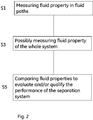
- FIG. 2 is a flow chart of the method of the invention according to one embodiment of the invention. The steps are described in order below:
- the evaluation of the separation system can be the measurement of residence time and/or chromatographic efficiency.
- the characteristic fluid property can be of type fluid flow rate, concentration, conductivity or changes in the absorption, reflection or extinction of light or energy.
- the comparison of sensor responses is done for the purpose of qualifying, monitoring or documenting the performance of the system.
- FIG 3 shows a pulse response diagram for one example according to the embodiment shown in Figure 1 .
- the curve denoted 51 shows the actual response on system level, i.e. measured by the system sensor 45.
- residence time is measured as the average residence time calculated by integration over the curve.
- residence time may be deducted from the residence time at the maximum pulse response (maximum height of the peak).
- the leading in the curve suggests that either one(or more) module(s) in the parallel system may deviate from the nominal response in terms of residence time or that at least one module may have a packed bed efficiency showing excessive leading.
- the curve denoted 53 shows the actual response as measured in the first sensor S1 in the first fluid path F1'. This is hereby the actual response from the first separation module M1' when run in parallel with the other separation modules M2', M3' of the system.
- the curve denoted 55 shows the actual response as measured in the second sensor S2 in the second fluid path F2'. This is hereby the actual response from the second separation module M2' when run in parallel with the other separation modules M1', M3' of the system.
- the curve denoted 57 shows the actual response as measured in the third sensor S3 in the third fluid path F3'. This is hereby the actual response from the third separation module M3' when run in parallel with the other separation modules M1', M2' of the system.
- all of the separation modules have residence time curves of symmetric shape, but one separation module, the first separation module M1', has a decreased average residence time. This reveals that the hydraulic resistance for this module is lower and the actual flow rate higher than for the other modules, respectively.
- the assessment of signals on the subsystem level gives full insight in the efficiency of the parallel assembly.
- Acceptance criteria for the performance of the individual separation modules as well as for the overall performance of the parallel assembly can be set and monitored at installation of the parallel assembly as well as before and throughout a process.
- Three main parameters would be measured and evaluated for a parallel assembly of chromatography modules:
- multiplexing techniques can be used.
- Muliplexing techniques allow the combined use of a common signal processing channel from or to the control system in order to sequentially access and modify the position of the control valves for example.
- multiplexing techniques allow for the sequential or simultaneous reading of sensor information to a transmitter or control system, respectively.
- the multiplexing principle is especially suitable for building a control system.
- multiplexing enabled as the sequential and cyclic reading of discrete sensor signals is also applicable due to the rather slow changes in the pulse response signals that are to be monitored at column modules and system.
Landscapes
- General Health & Medical Sciences (AREA)
- Health & Medical Sciences (AREA)
- Life Sciences & Earth Sciences (AREA)
- Chemical & Material Sciences (AREA)
- Analytical Chemistry (AREA)
- Biochemistry (AREA)
- Physics & Mathematics (AREA)
- General Physics & Mathematics (AREA)
- Immunology (AREA)
- Pathology (AREA)
- Treatment Of Liquids With Adsorbents In General (AREA)
- Physical Or Chemical Processes And Apparatus (AREA)
- Investigating Or Analyzing Materials By The Use Of Electric Means (AREA)
Claims (7)
- Verfahren zur Bewertung und/oder zur Kennzeichnung der Leistung eines Trennsystems (31), wobei das System eine Parallelanordnung (33) umfasst, einen Flüssigkeitseinlasspfad (35), der in die Parallelanordnung (33) eintritt, und einen Flüssigkeitsauslasspfad (37), der die Parallelanordnung (33) verlässt, wobei die Parallelanordnung (33) parallele Flüssigkeitspfade (F1', F2', ..., Fn') umfasst, die jeweils ein Trennmodul (M1', M2', ..., Mn') in Form eines Chromatographiemoduls umfasst, wobei das Verfahren die folgenden Schritte umfasst:Bereitstellung eines Sensors (S1, S2, ... Sn), der entweder in allen der parallelen Flüssigkeitspfade vom selben Typ ist, oder in allen der parallelen Flüssigkeitspfade mit der Ausnahme von einem vom selben Typ ist;Messen einer charakteristischen Flüssigkeitseigenschaft unter Verwendung der Sensoren zur Erzeugung einer Ansprechkurve für jeden Sensor;Messen derselben charakteristischen Flüssigkeitseigenschaft mit einem Systemsensor (45) desselben Typs, der in dem Auslass des Trennsystems (31) positioniert ist, um eine Systemansprechkurve zu erzeugen; undVergleichen der Ansprechkurven, um die Leistung des Trennsystems zu bewerten und/oder kennzuzeichnen, wobei das System dadurch gekennzeichnet ist, dass die Ansprechkurven bewertet werden, um Folgendes zu bestimmen:a) Durchschnittliche Verweilzeit in der jeweiligen Ansprechkurve (53, 55, 57) für jedes Modul in der Parallelanordnung, wobei die durchschnittlichen Verweilzeiten mit der durchschnittlichen Verweilzeit in der Ansprechkurve (51) des Systems verglichen werden;b) Chromatographische Effizienz hinsichtlich der Breite der Kurvenspitzen (53, 55, 57) für jedes Modul in der Parallelanordnung, wobei die Breiten der Kurvenspitzen mit der Breite einer Spitze für die Ansprechkurve (51) des Systems verglichen werden, oderc) Symmetrie der Kurvenspitzen (53, 55, 57) für jedes Modul in der Parallelanordnung, wobei die Symmetrien der Kurvenspitzen mit der Symmetrie in der Ansprechkurve des Systems verglichen werden.
- Verfahren nach Anspruch 1, wobei die charakteristische Flüssigkeitseigenschaft vom folgenden Typ ist:Flüssigkeitsfließgeschwindigkeit, Konzentration, Kraft, Druck, Temperatur, Leitfähigkeit, pH-Wert, oder Absorptionsgrad, Reflexionsgrad oder Emission von Licht, wie zum Beispiel die Messung des UV-Absorptionsgrades.
- Verfahren nach Anspruch 1 oder 2, wobei der Vergleich der Sensorantworten zum Zwecke der Kennzeichnung, Überwachung oder Dokumentation der Leistung des Systems geschieht.
- Trennungssystem (31), umfassend eine Parallelanordnung (33), einen Flüssigkeitseinlasspfad (35), der in die Parallelanordnung (33) eintritt, und einen Flüssigkeitsauslasspfad (37), der die Parallelanordnung (33) verlässt, wobei die Parallelanordnung (33) eine Anzahl paralleler Flüssigkeitspfade (F1', F2', ..., Fn') umfasst, wobei jeder parallele Flüssigkeitspfad ein Trennmodul (M1`, M2`, ..., Mn') in Form eines Chromatographiemoduls umfasst, wobei das Verfahren die folgenden Schritte umfasst und entweder jeder Flüssigkeitspfad einen Flüssigkeitseigenschaftssensor (S1, S2, ... Sn) vom selben Typ umfasst oder alle der Flüssigkeitspfade außer einem einen Sensor (S1, S2, ... Sn) vom selben Typ umfassen,
wobei das Trennungssystem ferner einen Flüssigkeitseigenschaftssensor (45) vom selben Typ umfasst, der im Auslass des Trennungssystems (31) positioniert ist, um das ganze Trennungssystem zu messen, wobei die Sensoren eine Messung einer Flüssigkeitseigenschaft bereitstellen, die verwendet wird, um eine Ansprechkurve zu erzeugen und wobei die Ansprechkurve von jedem Sensor mit der Ansprechkurve verglichen wird, die vom Systemsensor erzeugt wurde, wobei das System speziell angepasst ist, um die Ansprechkurven zu bewerten um Folgendes zu bestimmen:a) Durchschnittliche Verweilzeit in der jeweiligen Ansprechkurve (53, 55, 57) für jedes Modul in der Parallelanordnung, wobei die durchschnittlichen Verweilzeiten mit der durchschnittlichen Verweilzeit in der Ansprechkurve (51) des Systems verglichen werden;b) Chromatographische Effizienz hinsichtlich der Breite der Kurvenspitzen (53, 55, 57) für jedes Modul in der Parallelanordnung, wobei die Breiten der Kurvenspitzen mit der Breite einer Spitze für die Ansprechkurve (51) des Systems verglichen werden, oderc) Symmetrie der Kurvenspitzen (53, 55, 57) für jedes Modul in der Parallelanordnung, wobei die Symmetrien der Kurvenspitzen mit der Symmetrie in der Ansprechkurve (51) des Systems verglichen werden. - Trennungssystem nach Anspruch 4, wobei die Trennungsmodule (M1', M2', ..., Mn') wegwerfbar sind.
- Trennungssystem nach Anspruch 4 oder 5, wobei die Sensoren (S1, S2, ..., Sn) wegwerfbare Sonden sind.
- Trennungssystem nach den Ansprüchen 4 bis 6, wobei Sensorteile, die in Fluidkontakt sind, integrale Teile des Säulenmoduls sind.
Applications Claiming Priority (2)
| Application Number | Priority Date | Filing Date | Title |
|---|---|---|---|
| SE1050304 | 2010-03-31 | ||
| PCT/SE2011/050363 WO2011123040A1 (en) | 2010-03-31 | 2011-03-30 | A parallel separation system |
Publications (3)
| Publication Number | Publication Date |
|---|---|
| EP2552585A1 EP2552585A1 (de) | 2013-02-06 |
| EP2552585A4 EP2552585A4 (de) | 2014-06-04 |
| EP2552585B1 true EP2552585B1 (de) | 2016-05-25 |
Family
ID=44712489
Family Applications (1)
| Application Number | Title | Priority Date | Filing Date |
|---|---|---|---|
| EP11763152.3A Active EP2552585B1 (de) | 2010-03-31 | 2011-03-30 | Paralleles trennsystem |
Country Status (6)
| Country | Link |
|---|---|
| US (1) | US10830740B2 (de) |
| EP (1) | EP2552585B1 (de) |
| JP (1) | JP5947785B2 (de) |
| CN (1) | CN102821857B (de) |
| CA (1) | CA2793474A1 (de) |
| WO (1) | WO2011123040A1 (de) |
Families Citing this family (14)
| Publication number | Priority date | Publication date | Assignee | Title |
|---|---|---|---|---|
| US10391423B2 (en) | 2010-01-25 | 2019-08-27 | Spf Technologies Llc | Stackable planar adsorptive devices |
| US11395980B2 (en) | 2010-01-25 | 2022-07-26 | Spf Technologies Llc | Chromatographic cassette |
| US9120037B2 (en) | 2010-01-25 | 2015-09-01 | Spf Innovations, Llc | Stackable planar adsorptive devices |
| US11219844B2 (en) | 2010-01-25 | 2022-01-11 | Spf Technologies Llc | Stackable planar adsorptive devices |
| US10507409B2 (en) | 2016-03-12 | 2019-12-17 | Spf Technologies, Llc | Hyper-productive chromatography system and process |
| CN107249709B (zh) | 2014-12-18 | 2020-07-14 | 通用电气健康护理生物科学股份公司 | 基于压力探测的自动化层析柱切换控制 |
| ES2583128B1 (es) * | 2014-12-30 | 2019-06-21 | Abeinsa Epc Mexico S A De C V | Patin de medicion de vapor |
| GB201516992D0 (en) * | 2015-09-25 | 2015-11-11 | Ge Healthcare Bio Sciences Ab | Method and system for evaluation of an interaction between an analyte and a ligand using a biosensor |
| US12409440B1 (en) | 2016-01-26 | 2025-09-09 | Spf Technologies Llc | Separation module |
| GB201622342D0 (en) * | 2016-12-29 | 2017-02-15 | Ge Healthcare Bio Sciences Ab | Method in continuos chromatography |
| GB201703116D0 (en) | 2017-02-27 | 2017-04-12 | Ge Healthcare Bioprocess R&D Ab | A seperation matrix and a method of seperating antibodies |
| GB201810772D0 (en) | 2018-06-29 | 2018-08-15 | Ge Healthcare Bio Sciences Ab | Method in bioprocess purification system |
| ES3056969T3 (en) * | 2019-12-19 | 2026-02-25 | Hoffmann La Roche | Techniques for monitoring an analyzer including multiple liquid chromatography streams |
| WO2026078978A1 (ja) * | 2024-10-07 | 2026-04-16 | 株式会社日立ハイテク | 自動分析装置 |
Citations (2)
| Publication number | Priority date | Publication date | Assignee | Title |
|---|---|---|---|---|
| WO1995026796A1 (en) * | 1994-04-01 | 1995-10-12 | Integrated Chemical Synthesizers, Inc. | Integrated chemical synthesizers |
| WO2003066216A1 (de) * | 2002-02-04 | 2003-08-14 | Siemens Aktiengesellschaft | Mikrofluidik-system |
Family Cites Families (23)
| Publication number | Priority date | Publication date | Assignee | Title |
|---|---|---|---|---|
| JPS361698B1 (de) * | 1958-02-18 | 1961-03-18 | ||
| GB8304783D0 (en) * | 1983-02-21 | 1983-03-23 | Shell Int Research | Coriolis-type mass flow meter |
| JPS59152456U (ja) * | 1983-03-30 | 1984-10-12 | 株式会社島津製作所 | ガスクロマトグラフの試料気化室 |
| US4737275A (en) * | 1986-03-06 | 1988-04-12 | Autotrol Corporation | Resin pressure sensor for water treatment |
| WO2000012199A1 (de) | 1998-08-28 | 2000-03-09 | Bucher-Guyer Ag | Verfahren zur trennung eines gemisches in feste und flüssige anteile durch querstromfiltration |
| US6309541B1 (en) * | 1999-10-29 | 2001-10-30 | Ontogen Corporation | Apparatus and method for multiple channel high throughput purification |
| DE19957490C2 (de) * | 1998-11-20 | 2002-05-23 | Sepiatec Gmbh | Verfahren und Vorrichtung zur parallelen flüssigchromatographischen Trennung von Substanzen |
| JP2000266738A (ja) * | 1999-03-18 | 2000-09-29 | Hitachi Ltd | 液体クロマトグラフ質量分析装置 |
| US6360579B1 (en) * | 1999-03-26 | 2002-03-26 | Micro Motion, Inc. | Flowmeter calibration system with statistical optimization technique |
| DE60132185T2 (de) * | 2000-02-23 | 2009-01-02 | Caliper Life Sciences, Inc., Mountain View | Mehrfach-reservoir-drucksteuersystem |
| US6743356B1 (en) * | 2000-10-27 | 2004-06-01 | Johnson & Johnson | High throughput high performance chromatography system |
| US6439253B1 (en) * | 2000-12-28 | 2002-08-27 | International Business Machines Corporation | System for and method of monitoring the flow of semiconductor process gases from a gas delivery system |
| US7470545B2 (en) * | 2001-11-05 | 2008-12-30 | Rohm And Haas Company | Buccal dissolution of active substances |
| US20030150812A1 (en) * | 2001-12-19 | 2003-08-14 | Irving Wainer | Novel parallel throughput system |
| US20050051489A1 (en) * | 2003-08-20 | 2005-03-10 | California Institute Of Technology | IC-processed polymer nano-liquid chromatography system on-a-chip and method of making it |
| US20060169640A1 (en) * | 2005-02-01 | 2006-08-03 | Hubert Quinn | High throughput screening, purification and recovery system for large and small molecules |
| JP2006266738A (ja) | 2005-03-22 | 2006-10-05 | Denso Corp | 感度切換型センサ回路及び感度切換型センサ回路を用いる電子回路装置 |
| US7503340B2 (en) * | 2005-09-30 | 2009-03-17 | Agilent Technologies, Inc. | System and method for controlling fluid flow |
| US8920645B2 (en) | 2005-12-07 | 2014-12-30 | Tarpon Biosystems Inc. | Disposable chromatography valves and system |
| EP1850129A1 (de) * | 2006-12-08 | 2007-10-31 | Agilent Technologies, Inc. | Fluid-Trennsystem mit mehreren Fließkanälen |
| GB0703250D0 (en) * | 2007-02-20 | 2007-03-28 | Ge Healthcare Bio Sciences Ab | Ultrasonic flow meter |
| US20130179374A1 (en) * | 2012-01-06 | 2013-07-11 | General Electric Company | Custody transfer system and method for gas fuel |
| US9175810B2 (en) * | 2012-05-04 | 2015-11-03 | General Electric Company | Custody transfer system and method for gas fuel |
-
2011
- 2011-03-30 EP EP11763152.3A patent/EP2552585B1/de active Active
- 2011-03-30 US US13/638,676 patent/US10830740B2/en active Active
- 2011-03-30 CN CN201180018011.7A patent/CN102821857B/zh active Active
- 2011-03-30 CA CA2793474A patent/CA2793474A1/en not_active Abandoned
- 2011-03-30 JP JP2013502536A patent/JP5947785B2/ja active Active
- 2011-03-30 WO PCT/SE2011/050363 patent/WO2011123040A1/en not_active Ceased
Patent Citations (2)
| Publication number | Priority date | Publication date | Assignee | Title |
|---|---|---|---|---|
| WO1995026796A1 (en) * | 1994-04-01 | 1995-10-12 | Integrated Chemical Synthesizers, Inc. | Integrated chemical synthesizers |
| WO2003066216A1 (de) * | 2002-02-04 | 2003-08-14 | Siemens Aktiengesellschaft | Mikrofluidik-system |
Also Published As
| Publication number | Publication date |
|---|---|
| WO2011123040A1 (en) | 2011-10-06 |
| EP2552585A1 (de) | 2013-02-06 |
| US10830740B2 (en) | 2020-11-10 |
| CN102821857A (zh) | 2012-12-12 |
| CN102821857B (zh) | 2016-08-03 |
| EP2552585A4 (de) | 2014-06-04 |
| JP5947785B2 (ja) | 2016-07-06 |
| US20130020263A1 (en) | 2013-01-24 |
| CA2793474A1 (en) | 2011-10-06 |
| JP2013525749A (ja) | 2013-06-20 |
Similar Documents
| Publication | Publication Date | Title |
|---|---|---|
| US10830740B2 (en) | Parallel separation system | |
| US12611618B2 (en) | Parallel separation system | |
| EP3044559B1 (de) | Durchflussmessanordnung mit wirkdruckleitungen und verfahren zum erkennen von verstopften wirkdruckleitungen | |
| EP3234512B1 (de) | Durchflussmessanordnung nach dem differenzdruckmessprinzip | |
| AU2016369392B2 (en) | Method for monitoring at least two redundant sensors | |
| KR20210003824A (ko) | 크로마토그래피 컬럼 적격성 평가를 위한 전이 분석 방법 | |
| DE102007021564A1 (de) | Verfahren zur Temperaturmessung in Anlagenteilen | |
| CN102095608B (zh) | 用于原油自动取样器的检测校验系统及方法 | |
| CA2778344A1 (en) | Deposition sensor based on differential heat transfer resistance | |
| US20140139841A1 (en) | Fiber optic sensing apparatus including fiber gratings and method for sensing parameters involving different parameter modalities | |
| CN103217395A (zh) | 化学溶液浓度在线控制系统及方法 | |
| DE102008034079A1 (de) | Verfahren zur Erkennung und/oder Ermittlung einer Prozessgröße und entsprechende Vorrichtung | |
| AT505035B1 (de) | Vorrichtung und verfahren zur vermessung von strömungswiderständen | |
| DE102014208277A1 (de) | Sensor und Verfahren zum Erfassen zumindest einer messbaren Messgröße eines Mediums in einem Rohr | |
| Hussain et al. | Choosing Right Statistical Test for Data Analysis | |
| DE102017128565A1 (de) | Verfahren zur Sensorbestückung einer Prozessanlage | |
| DE102017109564A1 (de) | Verfahren zur Zustandsbestimmung von Sensoren | |
| US10472640B2 (en) | Method of real-time prognosis of flooding phenomenon in packed column | |
| CN111735976B (zh) | 基于检测设备的数据结果自动展示方法 | |
| Sriwongras et al. | The Measurement of Acoustic Emission Signals from Stem of Maize Under Controlled Environment | |
| AT11982U1 (de) | Vorrichtung zur messung der verformung eines konstruktionselementes | |
| Wazeer | EFFECT OF PROCESS VARIABILITY ON THE ECONOMIC VALUES OF AVERAGES CONTROL CHART PARAMETERS | |
| EP2811266A1 (de) | Durchflusssensor | |
| Christofides et al. | Fault-Detection and Isolation and Fault-Tolerant Control of Nonlinear Process Systems Using Asynchronous Measurements | |
| Barnett | EXPERT ANSWER |
Legal Events
| Date | Code | Title | Description |
|---|---|---|---|
| PUAI | Public reference made under article 153(3) epc to a published international application that has entered the european phase |
Free format text: ORIGINAL CODE: 0009012 |
|
| 17P | Request for examination filed |
Effective date: 20121022 |
|
| AK | Designated contracting states |
Kind code of ref document: A1 Designated state(s): AL AT BE BG CH CY CZ DE DK EE ES FI FR GB GR HR HU IE IS IT LI LT LU LV MC MK MT NL NO PL PT RO RS SE SI SK SM TR |
|
| DAX | Request for extension of the european patent (deleted) | ||
| A4 | Supplementary search report drawn up and despatched |
Effective date: 20140508 |
|
| RIC1 | Information provided on ipc code assigned before grant |
Ipc: B01J 47/14 20060101AFI20140429BHEP Ipc: G01N 30/28 20060101ALI20140429BHEP Ipc: G01N 30/46 20060101ALI20140429BHEP Ipc: B01D 15/18 20060101ALI20140429BHEP |
|
| 17Q | First examination report despatched |
Effective date: 20140625 |
|
| GRAP | Despatch of communication of intention to grant a patent |
Free format text: ORIGINAL CODE: EPIDOSNIGR1 |
|
| RIC1 | Information provided on ipc code assigned before grant |
Ipc: G01N 30/78 20060101ALN20151119BHEP Ipc: G01N 30/46 20060101ALI20151119BHEP Ipc: B01J 47/14 20060101AFI20151119BHEP Ipc: B01D 15/18 20060101ALI20151119BHEP |
|
| INTG | Intention to grant announced |
Effective date: 20151203 |
|
| RIC1 | Information provided on ipc code assigned before grant |
Ipc: B01D 15/18 20060101ALI20151123BHEP Ipc: G01N 30/78 20060101ALN20151123BHEP Ipc: B01J 47/14 20060101AFI20151123BHEP Ipc: G01N 30/46 20060101ALI20151123BHEP |
|
| GRAS | Grant fee paid |
Free format text: ORIGINAL CODE: EPIDOSNIGR3 |
|
| GRAA | (expected) grant |
Free format text: ORIGINAL CODE: 0009210 |
|
| RAP1 | Party data changed (applicant data changed or rights of an application transferred) |
Owner name: GE HEALTHCARE BIOPROCESS R&D AB |
|
| AK | Designated contracting states |
Kind code of ref document: B1 Designated state(s): AL AT BE BG CH CY CZ DE DK EE ES FI FR GB GR HR HU IE IS IT LI LT LU LV MC MK MT NL NO PL PT RO RS SE SI SK SM TR |
|
| REG | Reference to a national code |
Ref country code: GB Ref legal event code: FG4D |
|
| REG | Reference to a national code |
Ref country code: CH Ref legal event code: EP |
|
| REG | Reference to a national code |
Ref country code: IE Ref legal event code: FG4D Ref country code: AT Ref legal event code: REF Ref document number: 801801 Country of ref document: AT Kind code of ref document: T Effective date: 20160615 |
|
| REG | Reference to a national code |
Ref country code: DE Ref legal event code: R096 Ref document number: 602011026935 Country of ref document: DE |
|
| REG | Reference to a national code |
Ref country code: LT Ref legal event code: MG4D |
|
| REG | Reference to a national code |
Ref country code: NL Ref legal event code: MP Effective date: 20160525 |
|
| PG25 | Lapsed in a contracting state [announced via postgrant information from national office to epo] |
Ref country code: NO Free format text: LAPSE BECAUSE OF FAILURE TO SUBMIT A TRANSLATION OF THE DESCRIPTION OR TO PAY THE FEE WITHIN THE PRESCRIBED TIME-LIMIT Effective date: 20160825 Ref country code: NL Free format text: LAPSE BECAUSE OF FAILURE TO SUBMIT A TRANSLATION OF THE DESCRIPTION OR TO PAY THE FEE WITHIN THE PRESCRIBED TIME-LIMIT Effective date: 20160525 Ref country code: LT Free format text: LAPSE BECAUSE OF FAILURE TO SUBMIT A TRANSLATION OF THE DESCRIPTION OR TO PAY THE FEE WITHIN THE PRESCRIBED TIME-LIMIT Effective date: 20160525 Ref country code: FI Free format text: LAPSE BECAUSE OF FAILURE TO SUBMIT A TRANSLATION OF THE DESCRIPTION OR TO PAY THE FEE WITHIN THE PRESCRIBED TIME-LIMIT Effective date: 20160525 |
|
| REG | Reference to a national code |
Ref country code: AT Ref legal event code: MK05 Ref document number: 801801 Country of ref document: AT Kind code of ref document: T Effective date: 20160525 |
|
| PG25 | Lapsed in a contracting state [announced via postgrant information from national office to epo] |
Ref country code: ES Free format text: LAPSE BECAUSE OF FAILURE TO SUBMIT A TRANSLATION OF THE DESCRIPTION OR TO PAY THE FEE WITHIN THE PRESCRIBED TIME-LIMIT Effective date: 20160525 Ref country code: PT Free format text: LAPSE BECAUSE OF FAILURE TO SUBMIT A TRANSLATION OF THE DESCRIPTION OR TO PAY THE FEE WITHIN THE PRESCRIBED TIME-LIMIT Effective date: 20160926 Ref country code: RS Free format text: LAPSE BECAUSE OF FAILURE TO SUBMIT A TRANSLATION OF THE DESCRIPTION OR TO PAY THE FEE WITHIN THE PRESCRIBED TIME-LIMIT Effective date: 20160525 Ref country code: SE Free format text: LAPSE BECAUSE OF FAILURE TO SUBMIT A TRANSLATION OF THE DESCRIPTION OR TO PAY THE FEE WITHIN THE PRESCRIBED TIME-LIMIT Effective date: 20160525 Ref country code: GR Free format text: LAPSE BECAUSE OF FAILURE TO SUBMIT A TRANSLATION OF THE DESCRIPTION OR TO PAY THE FEE WITHIN THE PRESCRIBED TIME-LIMIT Effective date: 20160826 Ref country code: LV Free format text: LAPSE BECAUSE OF FAILURE TO SUBMIT A TRANSLATION OF THE DESCRIPTION OR TO PAY THE FEE WITHIN THE PRESCRIBED TIME-LIMIT Effective date: 20160525 |
|
| PG25 | Lapsed in a contracting state [announced via postgrant information from national office to epo] |
Ref country code: IT Free format text: LAPSE BECAUSE OF FAILURE TO SUBMIT A TRANSLATION OF THE DESCRIPTION OR TO PAY THE FEE WITHIN THE PRESCRIBED TIME-LIMIT Effective date: 20160525 |
|
| PG25 | Lapsed in a contracting state [announced via postgrant information from national office to epo] |
Ref country code: EE Free format text: LAPSE BECAUSE OF FAILURE TO SUBMIT A TRANSLATION OF THE DESCRIPTION OR TO PAY THE FEE WITHIN THE PRESCRIBED TIME-LIMIT Effective date: 20160525 Ref country code: SK Free format text: LAPSE BECAUSE OF FAILURE TO SUBMIT A TRANSLATION OF THE DESCRIPTION OR TO PAY THE FEE WITHIN THE PRESCRIBED TIME-LIMIT Effective date: 20160525 Ref country code: DK Free format text: LAPSE BECAUSE OF FAILURE TO SUBMIT A TRANSLATION OF THE DESCRIPTION OR TO PAY THE FEE WITHIN THE PRESCRIBED TIME-LIMIT Effective date: 20160525 Ref country code: RO Free format text: LAPSE BECAUSE OF FAILURE TO SUBMIT A TRANSLATION OF THE DESCRIPTION OR TO PAY THE FEE WITHIN THE PRESCRIBED TIME-LIMIT Effective date: 20160525 Ref country code: CZ Free format text: LAPSE BECAUSE OF FAILURE TO SUBMIT A TRANSLATION OF THE DESCRIPTION OR TO PAY THE FEE WITHIN THE PRESCRIBED TIME-LIMIT Effective date: 20160525 |
|
| PG25 | Lapsed in a contracting state [announced via postgrant information from national office to epo] |
Ref country code: SM Free format text: LAPSE BECAUSE OF FAILURE TO SUBMIT A TRANSLATION OF THE DESCRIPTION OR TO PAY THE FEE WITHIN THE PRESCRIBED TIME-LIMIT Effective date: 20160525 Ref country code: AT Free format text: LAPSE BECAUSE OF FAILURE TO SUBMIT A TRANSLATION OF THE DESCRIPTION OR TO PAY THE FEE WITHIN THE PRESCRIBED TIME-LIMIT Effective date: 20160525 Ref country code: PL Free format text: LAPSE BECAUSE OF FAILURE TO SUBMIT A TRANSLATION OF THE DESCRIPTION OR TO PAY THE FEE WITHIN THE PRESCRIBED TIME-LIMIT Effective date: 20160525 Ref country code: BE Free format text: LAPSE BECAUSE OF FAILURE TO SUBMIT A TRANSLATION OF THE DESCRIPTION OR TO PAY THE FEE WITHIN THE PRESCRIBED TIME-LIMIT Effective date: 20160525 |
|
| REG | Reference to a national code |
Ref country code: DE Ref legal event code: R097 Ref document number: 602011026935 Country of ref document: DE |
|
| REG | Reference to a national code |
Ref country code: FR Ref legal event code: PLFP Year of fee payment: 7 |
|
| PLBE | No opposition filed within time limit |
Free format text: ORIGINAL CODE: 0009261 |
|
| STAA | Information on the status of an ep patent application or granted ep patent |
Free format text: STATUS: NO OPPOSITION FILED WITHIN TIME LIMIT |
|
| 26N | No opposition filed |
Effective date: 20170228 |
|
| PG25 | Lapsed in a contracting state [announced via postgrant information from national office to epo] |
Ref country code: SI Free format text: LAPSE BECAUSE OF FAILURE TO SUBMIT A TRANSLATION OF THE DESCRIPTION OR TO PAY THE FEE WITHIN THE PRESCRIBED TIME-LIMIT Effective date: 20160525 |
|
| REG | Reference to a national code |
Ref country code: CH Ref legal event code: PL |
|
| PG25 | Lapsed in a contracting state [announced via postgrant information from national office to epo] |
Ref country code: MC Free format text: LAPSE BECAUSE OF FAILURE TO SUBMIT A TRANSLATION OF THE DESCRIPTION OR TO PAY THE FEE WITHIN THE PRESCRIBED TIME-LIMIT Effective date: 20160525 |
|
| REG | Reference to a national code |
Ref country code: IE Ref legal event code: MM4A |
|
| PG25 | Lapsed in a contracting state [announced via postgrant information from national office to epo] |
Ref country code: LU Free format text: LAPSE BECAUSE OF NON-PAYMENT OF DUE FEES Effective date: 20170330 |
|
| PG25 | Lapsed in a contracting state [announced via postgrant information from national office to epo] |
Ref country code: LI Free format text: LAPSE BECAUSE OF NON-PAYMENT OF DUE FEES Effective date: 20170331 Ref country code: CH Free format text: LAPSE BECAUSE OF NON-PAYMENT OF DUE FEES Effective date: 20170331 Ref country code: IE Free format text: LAPSE BECAUSE OF NON-PAYMENT OF DUE FEES Effective date: 20170330 |
|
| REG | Reference to a national code |
Ref country code: FR Ref legal event code: PLFP Year of fee payment: 8 |
|
| PG25 | Lapsed in a contracting state [announced via postgrant information from national office to epo] |
Ref country code: MT Free format text: LAPSE BECAUSE OF NON-PAYMENT OF DUE FEES Effective date: 20170330 |
|
| PG25 | Lapsed in a contracting state [announced via postgrant information from national office to epo] |
Ref country code: AL Free format text: LAPSE BECAUSE OF FAILURE TO SUBMIT A TRANSLATION OF THE DESCRIPTION OR TO PAY THE FEE WITHIN THE PRESCRIBED TIME-LIMIT Effective date: 20160525 |
|
| PG25 | Lapsed in a contracting state [announced via postgrant information from national office to epo] |
Ref country code: HU Free format text: LAPSE BECAUSE OF FAILURE TO SUBMIT A TRANSLATION OF THE DESCRIPTION OR TO PAY THE FEE WITHIN THE PRESCRIBED TIME-LIMIT; INVALID AB INITIO Effective date: 20110330 |
|
| PG25 | Lapsed in a contracting state [announced via postgrant information from national office to epo] |
Ref country code: BG Free format text: LAPSE BECAUSE OF FAILURE TO SUBMIT A TRANSLATION OF THE DESCRIPTION OR TO PAY THE FEE WITHIN THE PRESCRIBED TIME-LIMIT Effective date: 20160525 |
|
| PG25 | Lapsed in a contracting state [announced via postgrant information from national office to epo] |
Ref country code: CY Free format text: LAPSE BECAUSE OF NON-PAYMENT OF DUE FEES Effective date: 20160525 |
|
| PG25 | Lapsed in a contracting state [announced via postgrant information from national office to epo] |
Ref country code: MK Free format text: LAPSE BECAUSE OF FAILURE TO SUBMIT A TRANSLATION OF THE DESCRIPTION OR TO PAY THE FEE WITHIN THE PRESCRIBED TIME-LIMIT Effective date: 20160525 |
|
| PG25 | Lapsed in a contracting state [announced via postgrant information from national office to epo] |
Ref country code: TR Free format text: LAPSE BECAUSE OF FAILURE TO SUBMIT A TRANSLATION OF THE DESCRIPTION OR TO PAY THE FEE WITHIN THE PRESCRIBED TIME-LIMIT Effective date: 20160525 |
|
| PG25 | Lapsed in a contracting state [announced via postgrant information from national office to epo] |
Ref country code: HR Free format text: LAPSE BECAUSE OF FAILURE TO SUBMIT A TRANSLATION OF THE DESCRIPTION OR TO PAY THE FEE WITHIN THE PRESCRIBED TIME-LIMIT Effective date: 20160525 |
|
| PG25 | Lapsed in a contracting state [announced via postgrant information from national office to epo] |
Ref country code: IS Free format text: LAPSE BECAUSE OF FAILURE TO SUBMIT A TRANSLATION OF THE DESCRIPTION OR TO PAY THE FEE WITHIN THE PRESCRIBED TIME-LIMIT Effective date: 20160925 |
|
| REG | Reference to a national code |
Ref country code: DE Ref legal event code: R081 Ref document number: 602011026935 Country of ref document: DE Owner name: CYTIVA BIOPROCESS R&D AB, SE Free format text: FORMER OWNER: GE HEALTHCARE BIOPROCESS R&D AB, UPPSALA, SE |
|
| P01 | Opt-out of the competence of the unified patent court (upc) registered |
Effective date: 20230526 |
|
| PGFP | Annual fee paid to national office [announced via postgrant information from national office to epo] |
Ref country code: GB Payment date: 20260319 Year of fee payment: 16 |
|
| PGFP | Annual fee paid to national office [announced via postgrant information from national office to epo] |
Ref country code: DE Payment date: 20260320 Year of fee payment: 16 |
|
| PGFP | Annual fee paid to national office [announced via postgrant information from national office to epo] |
Ref country code: FR Payment date: 20260323 Year of fee payment: 16 |