EP2552679B1 - Verfahren und vorrichtung zur herstellung eines faserverstärkten thermoplastischen verbundbauteils - Google Patents
Verfahren und vorrichtung zur herstellung eines faserverstärkten thermoplastischen verbundbauteils Download PDFInfo
- Publication number
- EP2552679B1 EP2552679B1 EP11712770.4A EP11712770A EP2552679B1 EP 2552679 B1 EP2552679 B1 EP 2552679B1 EP 11712770 A EP11712770 A EP 11712770A EP 2552679 B1 EP2552679 B1 EP 2552679B1
- Authority
- EP
- European Patent Office
- Prior art keywords
- components
- component
- feed direction
- tool mold
- punch
- Prior art date
- Legal status (The legal status is an assumption and is not a legal conclusion. Google has not performed a legal analysis and makes no representation as to the accuracy of the status listed.)
- Active
Links
Images

Classifications
-
- B—PERFORMING OPERATIONS; TRANSPORTING
- B29—WORKING OF PLASTICS; WORKING OF SUBSTANCES IN A PLASTIC STATE IN GENERAL
- B29C—SHAPING OR JOINING OF PLASTICS; SHAPING OF MATERIAL IN A PLASTIC STATE, NOT OTHERWISE PROVIDED FOR; AFTER-TREATMENT OF THE SHAPED PRODUCTS, e.g. REPAIRING
- B29C70/00—Shaping composites, i.e. plastics material comprising reinforcements, fillers or preformed parts, e.g. inserts
- B29C70/04—Shaping composites, i.e. plastics material comprising reinforcements, fillers or preformed parts, e.g. inserts comprising reinforcements only, e.g. self-reinforcing plastics
- B29C70/28—Shaping operations therefor
- B29C70/30—Shaping by lay-up, i.e. applying fibres, tape or broadsheet on a mould, former or core; Shaping by spray-up, i.e. spraying of fibres on a mould, former or core
- B29C70/38—Automated lay-up, e.g. using robots, laying filaments according to predetermined patterns
- B29C70/386—Automated tape laying [ATL]
-
- B—PERFORMING OPERATIONS; TRANSPORTING
- B29—WORKING OF PLASTICS; WORKING OF SUBSTANCES IN A PLASTIC STATE IN GENERAL
- B29C—SHAPING OR JOINING OF PLASTICS; SHAPING OF MATERIAL IN A PLASTIC STATE, NOT OTHERWISE PROVIDED FOR; AFTER-TREATMENT OF THE SHAPED PRODUCTS, e.g. REPAIRING
- B29C43/00—Compression moulding, i.e. applying external pressure to flow the moulding material; Apparatus therefor
- B29C43/02—Compression moulding, i.e. applying external pressure to flow the moulding material; Apparatus therefor of articles of definite length, i.e. discrete articles
- B29C43/04—Compression moulding, i.e. applying external pressure to flow the moulding material; Apparatus therefor of articles of definite length, i.e. discrete articles using movable moulds
- B29C43/06—Compression moulding, i.e. applying external pressure to flow the moulding material; Apparatus therefor of articles of definite length, i.e. discrete articles using movable moulds continuously movable in one direction, e.g. mounted on chains, belts
-
- B—PERFORMING OPERATIONS; TRANSPORTING
- B29—WORKING OF PLASTICS; WORKING OF SUBSTANCES IN A PLASTIC STATE IN GENERAL
- B29C—SHAPING OR JOINING OF PLASTICS; SHAPING OF MATERIAL IN A PLASTIC STATE, NOT OTHERWISE PROVIDED FOR; AFTER-TREATMENT OF THE SHAPED PRODUCTS, e.g. REPAIRING
- B29C65/00—Joining or sealing of preformed parts, e.g. welding of plastics materials; Apparatus therefor
- B29C65/02—Joining or sealing of preformed parts, e.g. welding of plastics materials; Apparatus therefor by heating, with or without pressure
- B29C65/18—Joining or sealing of preformed parts, e.g. welding of plastics materials; Apparatus therefor by heating, with or without pressure using heated tools
-
- B—PERFORMING OPERATIONS; TRANSPORTING
- B29—WORKING OF PLASTICS; WORKING OF SUBSTANCES IN A PLASTIC STATE IN GENERAL
- B29C—SHAPING OR JOINING OF PLASTICS; SHAPING OF MATERIAL IN A PLASTIC STATE, NOT OTHERWISE PROVIDED FOR; AFTER-TREATMENT OF THE SHAPED PRODUCTS, e.g. REPAIRING
- B29C66/00—General aspects of processes or apparatus for joining preformed parts
- B29C66/01—General aspects dealing with the joint area or with the area to be joined
- B29C66/05—Particular design of joint configurations
- B29C66/10—Particular design of joint configurations particular design of the joint cross-sections
- B29C66/11—Joint cross-sections comprising a single joint-segment, i.e. one of the parts to be joined comprising a single joint-segment in the joint cross-section
- B29C66/112—Single lapped joints
-
- B—PERFORMING OPERATIONS; TRANSPORTING
- B29—WORKING OF PLASTICS; WORKING OF SUBSTANCES IN A PLASTIC STATE IN GENERAL
- B29C—SHAPING OR JOINING OF PLASTICS; SHAPING OF MATERIAL IN A PLASTIC STATE, NOT OTHERWISE PROVIDED FOR; AFTER-TREATMENT OF THE SHAPED PRODUCTS, e.g. REPAIRING
- B29C66/00—General aspects of processes or apparatus for joining preformed parts
- B29C66/01—General aspects dealing with the joint area or with the area to be joined
- B29C66/05—Particular design of joint configurations
- B29C66/10—Particular design of joint configurations particular design of the joint cross-sections
- B29C66/13—Single flanged joints; Fin-type joints; Single hem joints; Edge joints; Interpenetrating fingered joints; Other specific particular designs of joint cross-sections not provided for in groups B29C66/11 - B29C66/12
- B29C66/131—Single flanged joints, i.e. one of the parts to be joined being rigid and flanged in the joint area
-
- B—PERFORMING OPERATIONS; TRANSPORTING
- B29—WORKING OF PLASTICS; WORKING OF SUBSTANCES IN A PLASTIC STATE IN GENERAL
- B29C—SHAPING OR JOINING OF PLASTICS; SHAPING OF MATERIAL IN A PLASTIC STATE, NOT OTHERWISE PROVIDED FOR; AFTER-TREATMENT OF THE SHAPED PRODUCTS, e.g. REPAIRING
- B29C66/00—General aspects of processes or apparatus for joining preformed parts
- B29C66/01—General aspects dealing with the joint area or with the area to be joined
- B29C66/05—Particular design of joint configurations
- B29C66/301—Three-dimensional joints, i.e. the joined area being substantially non-flat
-
- B—PERFORMING OPERATIONS; TRANSPORTING
- B29—WORKING OF PLASTICS; WORKING OF SUBSTANCES IN A PLASTIC STATE IN GENERAL
- B29C—SHAPING OR JOINING OF PLASTICS; SHAPING OF MATERIAL IN A PLASTIC STATE, NOT OTHERWISE PROVIDED FOR; AFTER-TREATMENT OF THE SHAPED PRODUCTS, e.g. REPAIRING
- B29C66/00—General aspects of processes or apparatus for joining preformed parts
- B29C66/01—General aspects dealing with the joint area or with the area to be joined
- B29C66/345—Progressively making the joint, e.g. starting from the middle
- B29C66/3452—Making complete joints by combining partial joints
-
- B—PERFORMING OPERATIONS; TRANSPORTING
- B29—WORKING OF PLASTICS; WORKING OF SUBSTANCES IN A PLASTIC STATE IN GENERAL
- B29C—SHAPING OR JOINING OF PLASTICS; SHAPING OF MATERIAL IN A PLASTIC STATE, NOT OTHERWISE PROVIDED FOR; AFTER-TREATMENT OF THE SHAPED PRODUCTS, e.g. REPAIRING
- B29C66/00—General aspects of processes or apparatus for joining preformed parts
- B29C66/50—General aspects of joining tubular articles; General aspects of joining long products, i.e. bars or profiled elements; General aspects of joining single elements to tubular articles, hollow articles or bars; General aspects of joining several hollow-preforms to form hollow or tubular articles
- B29C66/51—Joining tubular articles, profiled elements or bars; Joining single elements to tubular articles, hollow articles or bars; Joining several hollow-preforms to form hollow or tubular articles
- B29C66/53—Joining single elements to tubular articles, hollow articles or bars
- B29C66/532—Joining single elements to the wall of tubular articles, hollow articles or bars
-
- B—PERFORMING OPERATIONS; TRANSPORTING
- B29—WORKING OF PLASTICS; WORKING OF SUBSTANCES IN A PLASTIC STATE IN GENERAL
- B29C—SHAPING OR JOINING OF PLASTICS; SHAPING OF MATERIAL IN A PLASTIC STATE, NOT OTHERWISE PROVIDED FOR; AFTER-TREATMENT OF THE SHAPED PRODUCTS, e.g. REPAIRING
- B29C66/00—General aspects of processes or apparatus for joining preformed parts
- B29C66/50—General aspects of joining tubular articles; General aspects of joining long products, i.e. bars or profiled elements; General aspects of joining single elements to tubular articles, hollow articles or bars; General aspects of joining several hollow-preforms to form hollow or tubular articles
- B29C66/61—Joining from or joining on the inside
-
- B—PERFORMING OPERATIONS; TRANSPORTING
- B29—WORKING OF PLASTICS; WORKING OF SUBSTANCES IN A PLASTIC STATE IN GENERAL
- B29C—SHAPING OR JOINING OF PLASTICS; SHAPING OF MATERIAL IN A PLASTIC STATE, NOT OTHERWISE PROVIDED FOR; AFTER-TREATMENT OF THE SHAPED PRODUCTS, e.g. REPAIRING
- B29C66/00—General aspects of processes or apparatus for joining preformed parts
- B29C66/70—General aspects of processes or apparatus for joining preformed parts characterised by the composition, physical properties or the structure of the material of the parts to be joined; Joining with non-plastics material
- B29C66/72—General aspects of processes or apparatus for joining preformed parts characterised by the composition, physical properties or the structure of the material of the parts to be joined; Joining with non-plastics material characterised by the structure of the material of the parts to be joined
- B29C66/721—Fibre-reinforced materials
-
- B—PERFORMING OPERATIONS; TRANSPORTING
- B29—WORKING OF PLASTICS; WORKING OF SUBSTANCES IN A PLASTIC STATE IN GENERAL
- B29C—SHAPING OR JOINING OF PLASTICS; SHAPING OF MATERIAL IN A PLASTIC STATE, NOT OTHERWISE PROVIDED FOR; AFTER-TREATMENT OF THE SHAPED PRODUCTS, e.g. REPAIRING
- B29C66/00—General aspects of processes or apparatus for joining preformed parts
- B29C66/70—General aspects of processes or apparatus for joining preformed parts characterised by the composition, physical properties or the structure of the material of the parts to be joined; Joining with non-plastics material
- B29C66/73—General aspects of processes or apparatus for joining preformed parts characterised by the composition, physical properties or the structure of the material of the parts to be joined; Joining with non-plastics material characterised by the intensive physical properties of the material of the parts to be joined, by the optical properties of the material of the parts to be joined, by the extensive physical properties of the parts to be joined, by the state of the material of the parts to be joined or by the material of the parts to be joined being a thermoplastic or a thermoset
- B29C66/739—General aspects of processes or apparatus for joining preformed parts characterised by the composition, physical properties or the structure of the material of the parts to be joined; Joining with non-plastics material characterised by the intensive physical properties of the material of the parts to be joined, by the optical properties of the material of the parts to be joined, by the extensive physical properties of the parts to be joined, by the state of the material of the parts to be joined or by the material of the parts to be joined being a thermoplastic or a thermoset characterised by the material of the parts to be joined being a thermoplastic or a thermoset
- B29C66/7392—General aspects of processes or apparatus for joining preformed parts characterised by the composition, physical properties or the structure of the material of the parts to be joined; Joining with non-plastics material characterised by the intensive physical properties of the material of the parts to be joined, by the optical properties of the material of the parts to be joined, by the extensive physical properties of the parts to be joined, by the state of the material of the parts to be joined or by the material of the parts to be joined being a thermoplastic or a thermoset characterised by the material of the parts to be joined being a thermoplastic or a thermoset characterised by the material of at least one of the parts being a thermoplastic
-
- B—PERFORMING OPERATIONS; TRANSPORTING
- B29—WORKING OF PLASTICS; WORKING OF SUBSTANCES IN A PLASTIC STATE IN GENERAL
- B29C—SHAPING OR JOINING OF PLASTICS; SHAPING OF MATERIAL IN A PLASTIC STATE, NOT OTHERWISE PROVIDED FOR; AFTER-TREATMENT OF THE SHAPED PRODUCTS, e.g. REPAIRING
- B29C66/00—General aspects of processes or apparatus for joining preformed parts
- B29C66/70—General aspects of processes or apparatus for joining preformed parts characterised by the composition, physical properties or the structure of the material of the parts to be joined; Joining with non-plastics material
- B29C66/73—General aspects of processes or apparatus for joining preformed parts characterised by the composition, physical properties or the structure of the material of the parts to be joined; Joining with non-plastics material characterised by the intensive physical properties of the material of the parts to be joined, by the optical properties of the material of the parts to be joined, by the extensive physical properties of the parts to be joined, by the state of the material of the parts to be joined or by the material of the parts to be joined being a thermoplastic or a thermoset
- B29C66/739—General aspects of processes or apparatus for joining preformed parts characterised by the composition, physical properties or the structure of the material of the parts to be joined; Joining with non-plastics material characterised by the intensive physical properties of the material of the parts to be joined, by the optical properties of the material of the parts to be joined, by the extensive physical properties of the parts to be joined, by the state of the material of the parts to be joined or by the material of the parts to be joined being a thermoplastic or a thermoset characterised by the material of the parts to be joined being a thermoplastic or a thermoset
- B29C66/7392—General aspects of processes or apparatus for joining preformed parts characterised by the composition, physical properties or the structure of the material of the parts to be joined; Joining with non-plastics material characterised by the intensive physical properties of the material of the parts to be joined, by the optical properties of the material of the parts to be joined, by the extensive physical properties of the parts to be joined, by the state of the material of the parts to be joined or by the material of the parts to be joined being a thermoplastic or a thermoset characterised by the material of the parts to be joined being a thermoplastic or a thermoset characterised by the material of at least one of the parts being a thermoplastic
- B29C66/73921—General aspects of processes or apparatus for joining preformed parts characterised by the composition, physical properties or the structure of the material of the parts to be joined; Joining with non-plastics material characterised by the intensive physical properties of the material of the parts to be joined, by the optical properties of the material of the parts to be joined, by the extensive physical properties of the parts to be joined, by the state of the material of the parts to be joined or by the material of the parts to be joined being a thermoplastic or a thermoset characterised by the material of the parts to be joined being a thermoplastic or a thermoset characterised by the material of at least one of the parts being a thermoplastic characterised by the materials of both parts being thermoplastics
-
- B—PERFORMING OPERATIONS; TRANSPORTING
- B29—WORKING OF PLASTICS; WORKING OF SUBSTANCES IN A PLASTIC STATE IN GENERAL
- B29C—SHAPING OR JOINING OF PLASTICS; SHAPING OF MATERIAL IN A PLASTIC STATE, NOT OTHERWISE PROVIDED FOR; AFTER-TREATMENT OF THE SHAPED PRODUCTS, e.g. REPAIRING
- B29C66/00—General aspects of processes or apparatus for joining preformed parts
- B29C66/80—General aspects of machine operations or constructions and parts thereof
- B29C66/81—General aspects of the pressing elements, i.e. the elements applying pressure on the parts to be joined in the area to be joined, e.g. the welding jaws or clamps
- B29C66/814—General aspects of the pressing elements, i.e. the elements applying pressure on the parts to be joined in the area to be joined, e.g. the welding jaws or clamps characterised by the design of the pressing elements, e.g. of the welding jaws or clamps
- B29C66/8141—General aspects of the pressing elements, i.e. the elements applying pressure on the parts to be joined in the area to be joined, e.g. the welding jaws or clamps characterised by the design of the pressing elements, e.g. of the welding jaws or clamps characterised by the surface geometry of the part of the pressing elements, e.g. welding jaws or clamps, coming into contact with the parts to be joined
- B29C66/81411—General aspects of the pressing elements, i.e. the elements applying pressure on the parts to be joined in the area to be joined, e.g. the welding jaws or clamps characterised by the design of the pressing elements, e.g. of the welding jaws or clamps characterised by the surface geometry of the part of the pressing elements, e.g. welding jaws or clamps, coming into contact with the parts to be joined characterised by its cross-section, e.g. transversal or longitudinal, being non-flat
- B29C66/81421—General aspects of the pressing elements, i.e. the elements applying pressure on the parts to be joined in the area to be joined, e.g. the welding jaws or clamps characterised by the design of the pressing elements, e.g. of the welding jaws or clamps characterised by the surface geometry of the part of the pressing elements, e.g. welding jaws or clamps, coming into contact with the parts to be joined characterised by its cross-section, e.g. transversal or longitudinal, being non-flat being convex or concave
- B29C66/81422—General aspects of the pressing elements, i.e. the elements applying pressure on the parts to be joined in the area to be joined, e.g. the welding jaws or clamps characterised by the design of the pressing elements, e.g. of the welding jaws or clamps characterised by the surface geometry of the part of the pressing elements, e.g. welding jaws or clamps, coming into contact with the parts to be joined characterised by its cross-section, e.g. transversal or longitudinal, being non-flat being convex or concave being convex
-
- B—PERFORMING OPERATIONS; TRANSPORTING
- B29—WORKING OF PLASTICS; WORKING OF SUBSTANCES IN A PLASTIC STATE IN GENERAL
- B29C—SHAPING OR JOINING OF PLASTICS; SHAPING OF MATERIAL IN A PLASTIC STATE, NOT OTHERWISE PROVIDED FOR; AFTER-TREATMENT OF THE SHAPED PRODUCTS, e.g. REPAIRING
- B29C66/00—General aspects of processes or apparatus for joining preformed parts
- B29C66/80—General aspects of machine operations or constructions and parts thereof
- B29C66/81—General aspects of the pressing elements, i.e. the elements applying pressure on the parts to be joined in the area to be joined, e.g. the welding jaws or clamps
- B29C66/814—General aspects of the pressing elements, i.e. the elements applying pressure on the parts to be joined in the area to be joined, e.g. the welding jaws or clamps characterised by the design of the pressing elements, e.g. of the welding jaws or clamps
- B29C66/8141—General aspects of the pressing elements, i.e. the elements applying pressure on the parts to be joined in the area to be joined, e.g. the welding jaws or clamps characterised by the design of the pressing elements, e.g. of the welding jaws or clamps characterised by the surface geometry of the part of the pressing elements, e.g. welding jaws or clamps, coming into contact with the parts to be joined
- B29C66/81411—General aspects of the pressing elements, i.e. the elements applying pressure on the parts to be joined in the area to be joined, e.g. the welding jaws or clamps characterised by the design of the pressing elements, e.g. of the welding jaws or clamps characterised by the surface geometry of the part of the pressing elements, e.g. welding jaws or clamps, coming into contact with the parts to be joined characterised by its cross-section, e.g. transversal or longitudinal, being non-flat
- B29C66/81421—General aspects of the pressing elements, i.e. the elements applying pressure on the parts to be joined in the area to be joined, e.g. the welding jaws or clamps characterised by the design of the pressing elements, e.g. of the welding jaws or clamps characterised by the surface geometry of the part of the pressing elements, e.g. welding jaws or clamps, coming into contact with the parts to be joined characterised by its cross-section, e.g. transversal or longitudinal, being non-flat being convex or concave
- B29C66/81423—General aspects of the pressing elements, i.e. the elements applying pressure on the parts to be joined in the area to be joined, e.g. the welding jaws or clamps characterised by the design of the pressing elements, e.g. of the welding jaws or clamps characterised by the surface geometry of the part of the pressing elements, e.g. welding jaws or clamps, coming into contact with the parts to be joined characterised by its cross-section, e.g. transversal or longitudinal, being non-flat being convex or concave being concave
-
- B—PERFORMING OPERATIONS; TRANSPORTING
- B29—WORKING OF PLASTICS; WORKING OF SUBSTANCES IN A PLASTIC STATE IN GENERAL
- B29C—SHAPING OR JOINING OF PLASTICS; SHAPING OF MATERIAL IN A PLASTIC STATE, NOT OTHERWISE PROVIDED FOR; AFTER-TREATMENT OF THE SHAPED PRODUCTS, e.g. REPAIRING
- B29C66/00—General aspects of processes or apparatus for joining preformed parts
- B29C66/80—General aspects of machine operations or constructions and parts thereof
- B29C66/81—General aspects of the pressing elements, i.e. the elements applying pressure on the parts to be joined in the area to be joined, e.g. the welding jaws or clamps
- B29C66/814—General aspects of the pressing elements, i.e. the elements applying pressure on the parts to be joined in the area to be joined, e.g. the welding jaws or clamps characterised by the design of the pressing elements, e.g. of the welding jaws or clamps
- B29C66/8141—General aspects of the pressing elements, i.e. the elements applying pressure on the parts to be joined in the area to be joined, e.g. the welding jaws or clamps characterised by the design of the pressing elements, e.g. of the welding jaws or clamps characterised by the surface geometry of the part of the pressing elements, e.g. welding jaws or clamps, coming into contact with the parts to be joined
- B29C66/81431—General aspects of the pressing elements, i.e. the elements applying pressure on the parts to be joined in the area to be joined, e.g. the welding jaws or clamps characterised by the design of the pressing elements, e.g. of the welding jaws or clamps characterised by the surface geometry of the part of the pressing elements, e.g. welding jaws or clamps, coming into contact with the parts to be joined comprising a single cavity, e.g. a groove
-
- B—PERFORMING OPERATIONS; TRANSPORTING
- B29—WORKING OF PLASTICS; WORKING OF SUBSTANCES IN A PLASTIC STATE IN GENERAL
- B29C—SHAPING OR JOINING OF PLASTICS; SHAPING OF MATERIAL IN A PLASTIC STATE, NOT OTHERWISE PROVIDED FOR; AFTER-TREATMENT OF THE SHAPED PRODUCTS, e.g. REPAIRING
- B29C66/00—General aspects of processes or apparatus for joining preformed parts
- B29C66/80—General aspects of machine operations or constructions and parts thereof
- B29C66/82—Pressure application arrangements, e.g. transmission or actuating mechanisms for joining tools or clamps
- B29C66/824—Actuating mechanisms
- B29C66/8242—Pneumatic or hydraulic drives
-
- B—PERFORMING OPERATIONS; TRANSPORTING
- B29—WORKING OF PLASTICS; WORKING OF SUBSTANCES IN A PLASTIC STATE IN GENERAL
- B29C—SHAPING OR JOINING OF PLASTICS; SHAPING OF MATERIAL IN A PLASTIC STATE, NOT OTHERWISE PROVIDED FOR; AFTER-TREATMENT OF THE SHAPED PRODUCTS, e.g. REPAIRING
- B29C66/00—General aspects of processes or apparatus for joining preformed parts
- B29C66/80—General aspects of machine operations or constructions and parts thereof
- B29C66/83—General aspects of machine operations or constructions and parts thereof characterised by the movement of the joining or pressing tools
- B29C66/834—General aspects of machine operations or constructions and parts thereof characterised by the movement of the joining or pressing tools moving with the parts to be joined
- B29C66/8351—Jaws mounted on rollers, cylinders, drums, bands, belts or chains; Flying jaws
- B29C66/83541—Jaws mounted on rollers, cylinders, drums, bands, belts or chains; Flying jaws flying jaws, e.g. jaws mounted on crank mechanisms or following a hand over hand movement
-
- B—PERFORMING OPERATIONS; TRANSPORTING
- B29—WORKING OF PLASTICS; WORKING OF SUBSTANCES IN A PLASTIC STATE IN GENERAL
- B29C—SHAPING OR JOINING OF PLASTICS; SHAPING OF MATERIAL IN A PLASTIC STATE, NOT OTHERWISE PROVIDED FOR; AFTER-TREATMENT OF THE SHAPED PRODUCTS, e.g. REPAIRING
- B29C66/00—General aspects of processes or apparatus for joining preformed parts
- B29C66/80—General aspects of machine operations or constructions and parts thereof
- B29C66/84—Specific machine types or machines suitable for specific applications
- B29C66/843—Machines for making separate joints at the same time in different planes; Machines for making separate joints at the same time mounted in parallel or in series
- B29C66/8432—Machines for making separate joints at the same time mounted in parallel or in series
-
- B—PERFORMING OPERATIONS; TRANSPORTING
- B29—WORKING OF PLASTICS; WORKING OF SUBSTANCES IN A PLASTIC STATE IN GENERAL
- B29C—SHAPING OR JOINING OF PLASTICS; SHAPING OF MATERIAL IN A PLASTIC STATE, NOT OTHERWISE PROVIDED FOR; AFTER-TREATMENT OF THE SHAPED PRODUCTS, e.g. REPAIRING
- B29C65/00—Joining or sealing of preformed parts, e.g. welding of plastics materials; Apparatus therefor
- B29C65/02—Joining or sealing of preformed parts, e.g. welding of plastics materials; Apparatus therefor by heating, with or without pressure
- B29C65/18—Joining or sealing of preformed parts, e.g. welding of plastics materials; Apparatus therefor by heating, with or without pressure using heated tools
- B29C65/24—Joining or sealing of preformed parts, e.g. welding of plastics materials; Apparatus therefor by heating, with or without pressure using heated tools characterised by the means for heating the tool
- B29C65/30—Electrical means
- B29C65/32—Induction
-
- B—PERFORMING OPERATIONS; TRANSPORTING
- B29—WORKING OF PLASTICS; WORKING OF SUBSTANCES IN A PLASTIC STATE IN GENERAL
- B29C—SHAPING OR JOINING OF PLASTICS; SHAPING OF MATERIAL IN A PLASTIC STATE, NOT OTHERWISE PROVIDED FOR; AFTER-TREATMENT OF THE SHAPED PRODUCTS, e.g. REPAIRING
- B29C66/00—General aspects of processes or apparatus for joining preformed parts
- B29C66/01—General aspects dealing with the joint area or with the area to be joined
- B29C66/02—Preparation of the material, in the area to be joined, prior to joining or welding
- B29C66/024—Thermal pre-treatments
- B29C66/0242—Heating, or preheating, e.g. drying
-
- B—PERFORMING OPERATIONS; TRANSPORTING
- B29—WORKING OF PLASTICS; WORKING OF SUBSTANCES IN A PLASTIC STATE IN GENERAL
- B29C—SHAPING OR JOINING OF PLASTICS; SHAPING OF MATERIAL IN A PLASTIC STATE, NOT OTHERWISE PROVIDED FOR; AFTER-TREATMENT OF THE SHAPED PRODUCTS, e.g. REPAIRING
- B29C66/00—General aspects of processes or apparatus for joining preformed parts
- B29C66/01—General aspects dealing with the joint area or with the area to be joined
- B29C66/03—After-treatments in the joint area
- B29C66/034—Thermal after-treatments
- B29C66/0342—Cooling, e.g. transporting through welding and cooling zone
-
- B—PERFORMING OPERATIONS; TRANSPORTING
- B29—WORKING OF PLASTICS; WORKING OF SUBSTANCES IN A PLASTIC STATE IN GENERAL
- B29C—SHAPING OR JOINING OF PLASTICS; SHAPING OF MATERIAL IN A PLASTIC STATE, NOT OTHERWISE PROVIDED FOR; AFTER-TREATMENT OF THE SHAPED PRODUCTS, e.g. REPAIRING
- B29C66/00—General aspects of processes or apparatus for joining preformed parts
- B29C66/70—General aspects of processes or apparatus for joining preformed parts characterised by the composition, physical properties or the structure of the material of the parts to be joined; Joining with non-plastics material
- B29C66/72—General aspects of processes or apparatus for joining preformed parts characterised by the composition, physical properties or the structure of the material of the parts to be joined; Joining with non-plastics material characterised by the structure of the material of the parts to be joined
- B29C66/721—Fibre-reinforced materials
- B29C66/7212—Fibre-reinforced materials characterised by the composition of the fibres
-
- B—PERFORMING OPERATIONS; TRANSPORTING
- B29—WORKING OF PLASTICS; WORKING OF SUBSTANCES IN A PLASTIC STATE IN GENERAL
- B29L—INDEXING SCHEME ASSOCIATED WITH SUBCLASS B29C, RELATING TO PARTICULAR ARTICLES
- B29L2031/00—Other particular articles
- B29L2031/001—Profiled members, e.g. beams, sections
- B29L2031/003—Profiled members, e.g. beams, sections having a profiled transverse cross-section
-
- B—PERFORMING OPERATIONS; TRANSPORTING
- B29—WORKING OF PLASTICS; WORKING OF SUBSTANCES IN A PLASTIC STATE IN GENERAL
- B29L—INDEXING SCHEME ASSOCIATED WITH SUBCLASS B29C, RELATING TO PARTICULAR ARTICLES
- B29L2031/00—Other particular articles
- B29L2031/30—Vehicles, e.g. ships or aircraft, or body parts thereof
- B29L2031/3076—Aircrafts
- B29L2031/3082—Fuselages
-
- Y—GENERAL TAGGING OF NEW TECHNOLOGICAL DEVELOPMENTS; GENERAL TAGGING OF CROSS-SECTIONAL TECHNOLOGIES SPANNING OVER SEVERAL SECTIONS OF THE IPC; TECHNICAL SUBJECTS COVERED BY FORMER USPC CROSS-REFERENCE ART COLLECTIONS [XRACs] AND DIGESTS
- Y10—TECHNICAL SUBJECTS COVERED BY FORMER USPC
- Y10T—TECHNICAL SUBJECTS COVERED BY FORMER US CLASSIFICATION
- Y10T156/00—Adhesive bonding and miscellaneous chemical manufacture
- Y10T156/10—Methods of surface bonding and/or assembly therefor
Definitions
- the invention relates to a method for producing a fiber-reinforced thermoplastic composite component according to the preamble of patent claim 1, for example a shell element of an aircraft fuselage, as well as a device for carrying out the method according to the preamble of patent claim 9.
- Fiber-reinforced composite components such as shell elements of an aircraft fuselage, are known to have a rear structure consisting of a plurality of longitudinal stiffeners, which are connected directly to a skin panel, and a plurality of circumferential stiffeners, which are connected via fittings or clips on the skin panel and additionally on supporting elements or cleats are supported on the longitudinal stiffeners.
- the US 6 613 258 B1 describes a method of making large-sized parts molded from a skin and reinforcing elements, such as fuselage segments of an aircraft made from a composite with a thermoplastic matrix. After reinforcing elements are manufactured separately by draping, solidification and shaping, these reinforcing elements are placed on a mold and the Skin is made simultaneously and joined together with the reinforcing elements by diffusion bonding. More specifically, the skin is draped by the draping head and solidified continuously, so that the required part is directly obtained. This hardened longitudinal stiffeners are placed in wells of a cylindrical core. Then the core is around his Longitudinal axis rotated and unwound a web-like laminate on the core.
- the deposition of the laminate takes place via a deposition head by means of temperature and pressure, whereby the thermoplastic matrix is melted and the laminate is firmly welded to the longitudinal stiffeners.
- a disadvantage of this solution are the very tight manufacturing tolerances of the hulled tubs.
- the object of the present invention is to provide a method for producing a fiber-reinforced thermoplastic composite component, which eliminates the aforementioned disadvantages and forms an optimal compromise between the manufacturing effort, the assembly costs and the manufacturing tolerance, as well as an apparatus for performing this method.
- a method according to the invention for producing a fiber-reinforced thermoplastic composite component which consists of a plurality of component components and is, for example, a shell element of an aircraft reinforced with stiffening elements
- the component components are positioned relative to one another by means of a tool mold which images the geometry of the composite component.
- the component components are moved continuously in the feed direction and connected in sections via a movable in the feed direction and in the opposite direction press ram.
- the solution according to the invention combines various technologies such as the pressing and welding of thermoplastic components in a continuous production process for the production of large components.
- various technologies such as the pressing and welding of thermoplastic components in a continuous production process for the production of large components.
- the pressing die for connecting the component components is moved from a starting position in the feed direction of the component components and then moved in the opposite direction after connecting the component components.
- the press ram is virtually guided in a circle, which allows a relatively simple control.
- the movement of the ram in the feed and in the opposite direction is particularly easy to carry out when the ram is moved after lifting back to the starting position.
- the movement of the press ram in the feed direction depends in particular on its extension in the feed direction.
- the ram in the feed direction has an extension which is greater than a feed path. This ensures that overlapping pressing areas result during pressing, so that it is ensured that the component components are welded or glued to one another over the entire composite component.
- At least one of the component components is deposited continuously before the pressing process. This eliminates the storage of the respective component components, so that long throughput times by transfer between different manufacturing means are not necessary. It is advantageous if at least one component component is heated prior to depositing such that its thermoplastic matrix is melted.
- At least some of the component components in the solidified (thermoplastic "does not cure” as Duroplast off.) State stored on the mold. This facilitates in particular the handling of the component components and their positioning on the mold.
- a device according to the invention for producing a fiber-reinforced thermoplastic composite component has a tool mold for positioning individual component components relative to one another, which can be moved in a feed direction, and a press die which can be moved in the feed direction and in the opposite direction for welding the component components.
- the device according to the invention allows the continuous production of large components, such as shell elements for an aircraft fuselage, which are reinforced via a rear structure. In this case, the device is very compact executable because the press ram does not have to extend over the entire extension of the mold in the feed direction due to its given in the feed direction and in the opposite direction traversability.
- the device according to the invention allows the movement of the press ram quasi in a circular path, so that the ram itself has to show only a fraction of the extension of the mold in the longitudinal direction. In this case, the compactness of the ram can be further increased if this is also movable in the transverse direction.
- At least one heating device for example an induction welding device, is arranged in the tool mold in the region of the component parts to be accommodated.
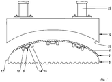
- FIG. 1 shows a device according to the invention for producing a fiber-reinforced, for example, reinforced with carbon fibers, shell element 2 thermoplastic based for the manufacture of an aircraft fuselage.
- the shell element 2 consists of a fiber-reinforced thermoplastic skin panel 4 and a plurality of integral fiber-reinforced thermoplastic longitudinal stiffeners 6 for reinforcing the skin panel 4.
- Other stiffeners such as circumferential stiffeners are not shown for reasons of clarity. These can also be formed integrally with the skin panel 4 or connected later.
- the tool 1 has a lower die 8 and an upper punch 10.
- the die 8 is longitudinally movable and has a concave surface 12 corresponding to the geometry of the fuselage for depositing layers of laminate to form the skin panel 4 in which a plurality of longitudinally the tool mold 8 extending recesses 14 for receiving the longitudinal stiffeners 6 is formed.
- the Longitudinal stiffeners 6 designed as omega profiles, which are welded or glued in the region of their foot sections 16 with the skin panel 4.
- the foot portions 16 are supported on a respective heating device 18 arranged in the tool mold 8 in the region of the depressions 14, for example an induction welding device.
- the press ram 10 has a convex mating surface 20 complementary to the surface 12 of the tool mold 8, which extends substantially over the entire width of the surface 12, so that the skin panel 4 is clamped completely between the ram 10 and the tool mold 8 in a transverse pressing step can be. It is movable via a cylinder piston arrangement 22 orthogonal to the tool mold 8 and in the feed direction and in the opposite direction of the tool mold 8.
- the press ram 10 has a heating device, not shown, for example an induction heating device.
- thermoplastic longitudinal stiffeners 6 are positioned in the recesses 14 of the mold 8.
- the fiber-reinforced thermoplastic laminate for forming the skin panel 4 is continuously supplied to the surface 12 and thus via the foot portions 16 of the longitudinal stiffeners 6.
- the laminate layers have been previously heated in a furnace (not shown) in such a way that their thermoplastic matrix has a viscosity suitable for the press molding process when placed on the mold 8.
- the press die is heated to a temperature adapted to the desired material properties of the thermoplastic and, from its starting position, executes a lowering movement 24 in the direction of the deposited molten laminate layers that they are welded by pressure and Temperaturbeaufschlagung with the foot sections 16 of the longitudinal reinforcements 6 and also lie konturnah on the surface 12 and solidify there.
- at least the contact points of the skin panel 4 and the longitudinal stiffeners 6 to be welded are heated in a controlled manner via the induction welding devices 18 in order to promote the welding.
- the tool mold 8 and the ram 10 are moved in the longitudinal direction L or feed direction 26 at the same speed so that the relative speed difference between the tool mold 8 and the press ram 10 moving in the same direction is zero.
- the press ram 10 is actuated such that it performs a lifting movement 28 in the direction away from the tool mold 8.
- the tool mold 8 continues to perform a continuous feed movement in the longitudinal direction L. After lifting the ram 10 of this is guided over a movement 30 in the opposite direction back to its starting position. After reaching its starting position, the ram 10 has virtually described a circular motion, which is repeated until the skin panel 4 is welded over its entire length with the longitudinal stiffeners 6.
- the movement in the feed direction 26 of the ram 10 corresponds to a fraction of its physical extent in the feed direction 26, so that at each circular movement between the ram 10 and the Skin field 4 overlap areas are formed and at least small areas, if not every section of the skin field is subjected to two times temperature and pressure.
- the shell element 2 is removed from the tool mold 8 or the required skin field length is separated from the skin field strand leaving the press continuously and a possibly further mechanical treatment for smoothing of component edges, introduction of window cutouts, door cutouts and the like fed.
- Disclosed is a method for producing a fiber-reinforced thermoplastic composite component from a plurality of component components which are moved continuously in the feed direction and are connected in sections by a movable in the feed direction and in the opposite direction pressing punch together, and an apparatus for performing the method.
Landscapes
- Engineering & Computer Science (AREA)
- Mechanical Engineering (AREA)
- Physics & Mathematics (AREA)
- Robotics (AREA)
- Chemical & Material Sciences (AREA)
- Composite Materials (AREA)
- Fluid Mechanics (AREA)
- Moulding By Coating Moulds (AREA)
- Casting Or Compression Moulding Of Plastics Or The Like (AREA)
- Thermal Sciences (AREA)
Description
- Die Erfindung betrifft ein Verfahren zur Herstellung eines faserverstärkten thermoplastischen Verbundbauteils nach dem Oberbegriff des Patentanspruchs 1, beispielsweise ein Schalenelement eines Flugzeugrumpfes, sowie eine Vorrichtung zur Durchführung des Verfahrens nach dem Oberbegriff des Patentanspruchs 9.
- Faserverstärkte Verbundbauteile wie Schalenelemente eines Flugzeugrumpfes, weisen bekanntermaßen eine Hinterbaustruktur bestehend aus einer Vielzahl von Längsversteifungen, die unmittelbar an einem Hautfeld angebunden sind, und einer Vielzahl von Umfangsversteifungen auf, die über Beschläge bzw. Clips an dem Hautfeld angebunden und zusätzlich über Abstützelemente bzw. Cleats an den Längsversteifungen abgestützt sind.
- Die Herstellung derartiger Rumpfsegmente erfolgt entweder in Differenzialbauweise oder in Integralbauweise. Bei der Differenzialbauweise werden die einzelnen Komponenten separat voneinander gefertigt und anschließend zum Gesamtbauteil montiert. Nachteilig an dieser Bauweise sind insbesondere die zeit- und kostenintensive Montage des Gesamtbauteils. Des Weiteren erfordert die Differenzialbauweise eine Vielzahl von Verbindungselementen zur Verbindung der Bauteilkomponenten untereinander. Die Integralbauweise, bei der die Einzelkomponenten integral als ein Gesamtbauteil gefertigt werden, zeichnet sich durch einen reduzierten Montageaufwand und aufgrund der Steigerung des Integrationsgrades durch einen erhöhten Fertigungsaufwand aus. Zur Reduzierung des Fertigungsaufwandes schlägt beispielsweise das Patent
US 6 613 258 B1 vor, eine Rumpftonne aus faserverstärkten thermoplastischen Verbundmaterialien herzustellen. DieUS 6 613 258 B1 beschreibt ein Verfahren zur Herstellung von Teilen mit großen Dimensionen, die aus einer Haut und Verstärkungselementen geformt sind, wie beispielsweise aus einem Verbundwerkstoff mit einer thermoplastischen Matrix hergestellte Rumpfsegmente eines Luftfahrzeugs. Nachdem Verstärkungselemente separat durch Drapierung, Verfestigung und Formgebung hergestellt sind, werden diese Verstärkungselemente auf einem Formwerkzeug angeordnet und die Haut wird simultan hergestellt und mit den Verstärkungselementen durch Diffusionsschweißen zusammengefügt. Genauer gesagt, wird die Haut durch den Drapierkopf drapiert und fortwährend verfestigt, so dass das benötigte Teil direkt erhalten wird. Dabei werden ausgehärtete Längsversteifungen in Vertiefungen eines zylindrischen Kerns gelegt. Anschließend wird der Kern um seine Längsachse in Rotation versetzt und ein bahnartiges Laminat auf dem Kern abgewickelt. Das Ablegen des Laminates erfolgt über einen Ablegekopf mittels Temperatur- und Druckbeaufschlagung, wodurch die Thermoplastmatrix aufgeschmolzen und das Laminat fest mit den Längsversteifungen verschweißt wird. Nachteilig an dieser Lösung sind jedoch die sehr engen Fertigungstoleranzen der Rumpftonnen. - Die Aufgabe der vorliegenden Erfindung ist es, ein Verfahren zur Herstellung eines faserverstärkten thermoplastischen Verbundbauteils, das die vorgenannten Nachteile beseitigt und einen optimalen Kompromiss zwischen dem Fertigungsaufwand, dem Montageaufwand und der Fertigungstoleranz bildet, sowie eine Vorrichtung zur Durchführung dieses Verfahrens zu schaffen.
- Diese Aufgabe wird gelöst durch ein Verfahren mit den Merkmalen des Patentanspruchs 1 sowie durch eine Vorrichtung mit den Merkmalen des Patentanspruchs 9.
- Bei einem erfindungsgemäßen Verfahren zur Herstellung eines faserverstärkten thermoplastischen Verbundbauteils, das aus einer Vielzahl von Bauteilkomponenten besteht und beispielsweise ein mit Versteifungselementen verstärktes Schalenelement eines Flugzeuges ist, werden die Bauteilkomponenten mittels einer die Geometrie des Verbundbauteils abbildenden Werkzeugform zueinander positioniert. Erfindungsgemäß werden die Bauteilkomponenten kontinuierlich in Vorschubrichtung bewegt und abschnittsweise über einen in Vorschubrichtung und in Gegenrichtung verfahrbaren Pressstempel miteinander verbunden. Das erfindungsgemäße Verfahren schafft einen optimalen Kompromiss zwischen dem Montageaufwand, dem Fertigungsaufwand und den Fertigungstoleranzen. Zwar wird durch die Schalenbauweise der Fertigungsaufwand gegenüber der gewickelten Tonnenbauweise gesteigert, jedoch erlaubt die Schalenbauweise einen verbesserten Toleranzausgleich. Die erfindungsgemäße Lösung vereinigt verschiedene Technologien wie das Pressen und Schweißen von thermoplastischen Bauteilen in einem kontinuierlichen Produktionsprozess zur Herstellung von Großbauteilen. Durch die kontinuierliche Bewegung der Bauteilkomponenten in Vorschubrichtung und durch die Verfahrbarkeit des Pressstempels in Vorschub- und in Gegenrichtung kann der Pressstempel entsprechend kompakt ausgeführt sein. Die Bauteilgröße ist quasi losgelöst von der Größe des Pressstempels, so dass beliebig bzw. nahezu beliebig große thermoplastische Verbundbauteile mit dem erfindungsgemäßen Verfahren hergestellt werden können.
- Bei einem bevorzugten Ausführungsbeispiel wird der Pressstempel zum Verbinden der Bauteilkomponenten aus einer Startposition in Vorschubrichtung der Bauteilkomponenten verfahren und anschließend nach dem Verbinden der Bauteilkomponenten in Gegenrichtung bewegt. Hierdurch wird der Pressstempel quasi im Kreis geführt, was eine verhältnismäßig einfache Steuerung ermöglicht. Die Bewegung des Pressstempels in Vorschub- und in Gegenrichtung ist besonders einfach ausführbar, wenn der Pressstempel nach dem Anheben zurück zur Startposition bewegt wird.
- Die Bewegung des Pressstempels in Vorschubrichtung richtet sich insbesondere nach seiner Erstreckung in Vorschubrichtung. Vorzugsweise hat der Pressstempel in Vorschubrichtung eine Erstreckung, die größer ist als ein Vorschubweg. Hierdurch wird gewährleistet, dass sich beim Pressen überlappende Pressbereiche ergeben, so dass sichergestellt ist, dass die Bauteilkomponenten über das gesamte Verbundbauteil miteinander verschweißt bzw. verklebt werden.
- Bei einem Ausführungsbeispiel wird zumindest eine der Bauteilkomponenten, beispielsweise ein Laminat zur Herstellung des Hautfeldes, kontinuierlich vor dem Pressvorgang abgelegt. Hierdurch entfällt die Lagerung der jeweiligen Bauteilkomponenten, so dass lange Durchlaufzeiten durch Transfer zwischen unterschiedlichen Fertigungsmitteln nicht notwendig sind. Dabei ist es vorteilhaft, wenn zumindest eine Bauteilkomponente vor dem Ablegen derart erwärmt wird, dass ihre Thermoplastmatrix aufgeschmolzen ist.
- Vorzugsweise werden zumindest einige der Bauteilkomponenten im erstarrten (Thermoplast "härtet" nicht wie Duroplast aus.) Zustand auf der Werkzeugform abgelegt. Dies erleichtert insbesondere die Handhabung der Bauteilkomponenten und deren Positionierung auf der Werkzeugform.
- Zur Erzielung einer definierten Polymerstruktur ist es vorteilhaft, wenn die Bauteilkomponenten beim Verbinden durch den Pressstempel kontrolliert abgekühlt werden.
- Eine erfindungsgemäße Vorrichtung zur Herstellung eines faserverstärkten thermoplastischen Verbundbauteils hat eine Werkzeugform zur Positionierung einzelner Bauteilkomponenten zueinander, die in eine Vorschubrichtung bewegbar ist, und einen in Vorschubrichtung und in Gegenrichtung verfahrbaren Pressstempel zum Verschweißen der Bauteilkomponenten. Die erfindungsgemäße Vorrichtung erlaubt die kontinuierliche Fertigung von Großbauteilen, wie beispielsweise Schalenelemente für einen Flugzeugrumpf, die über eine Hinterbaustruktur verstärkt sind. Dabei ist die Vorrichtung sehr kompakt ausführbar, da sich der Pressstempel aufgrund seiner in Vorschubrichtung und in Gegenrichtung gegebenen Verfahrbarkeit nicht über die gesamte Erstreckung der Werkzeugform in Vorschubrichtung erstrecken muss. Die erfindungsgemäße Vorrichtung erlaubt die Bewegung des Pressstempels quasi in einer Kreisbahn, so dass der Pressstempel an sich nur einen Bruchteil der Erstreckung der Werkzeugform in Längsrichtung aufzuweisen hat. Dabei kann die Kompaktheit des Pressstempels weiter gesteigert werden, wenn dieser auch in Querrichtung bewegbar ist.
- Zur Erreichung von hohen Konsolidierungsgraden ist es vorteilhaft, wenn in der Werkzeugform im Bereich der aufzunehmenden Bauteilkomponenten zumindest jeweils eine Heizeinrichtung, beispielsweise eine Induktionsschweißeinrichtung, angeordnet ist.
- Sonstige vorteilhafte Ausführungsbeispiele der vorliegenden Erfindung sind Gegenstand weiterer Unteransprüche.
- Im Folgenden werden bevorzugte Ausführungsbeispiele der vorliegenden Erfindung anhand schematischer Darstellungen näher erläutert. Es zeigen:
-
Figur 1 einen Querschnitt durch eine erfindungsgemäßen Vorrichtung und -
Figur 2 ein erfindungsgemäßes Verfahren. - In den Figuren tragen gleiche konstruktive Elemente die gleichen Bezugsziffern, wobei aus Gründen der Übersichtlichkeit bei mehreren gleichen konstruktiven Elementen in einer Figur lediglich ein Element mit einer Bezugsziffer versehen ist.
-
Figur 1 zeigt eine erfindungsgemäße Vorrichtung zur Herstellung eines faserverstärkten, beispielsweise mit Kohlenstofffasern verstärkten, Schalenelementes 2 auf Thermoplastbasis zur Herstellung eines Flugzeugrumpfes. Das Schalenelement 2 besteht aus einem faserverstärkten thermoplastischen Hautfeld 4 und einer Vielzahl von integralen faserverstärkten thermoplastischen Längsversteifungen 6 zur Verstärkung des Hautfeldes 4. Weitere Versteifungen wie Umfangsversteifungen sind aus Gründen der Übersichtlichkeit nicht dargestellt. Diese können ebenfalls integral mit dem Hautfeld 4 ausgebildet oder nachträglich angebunden werden. - Die Vorrichtung 1 hat eine untere Werkzeugform 8 sowie einen oberen Pressstempel 10. Die Werkzeugform 8 ist in Längsrichtung verfahrbar und hat eine der Geometrie des Flugzeugrumpfes entsprechende konkave Oberfläche 12 zum Ablegen von Laminatschichten zur Bildung des Hautfeldes 4, in der eine Vielzahl von sich in Längsrichtung der Werkzeugform 8 erstreckende Vertiefungen 14 zur Aufnahme der Längsversteifungen 6 ausgebildet ist. In dem gezeigten Ausführungsbeispiel sind die Längsversteifungen 6 als Omega-Profile ausgebildet, die im Bereich ihrer Fußabschnitte 16 mit dem Hautfeld 4 verschweißt bzw. verklebt sind. Zur Erzielung eines hohen Konsolidierungsgrades stützen sich die Fußabschnitte 16 auf jeweils einer in der Werkzeugform 8 im Bereich der Vertiefungen 14 angeordneten Heizeinrichtung 18, beispielsweise eine Induktionsschweißeinrichtung, ab.
- Der Pressstempel 10 hat eine zur Oberfläche 12 der Werkzeugform 8 komplementär geformte konvexe Gegenfläche 20, die sich im Wesentlichen über die gesamte Breite der Oberfläche 12 erstreckt, so dass das Hautfeld 4 in einem Pressschritt in Querrichtung vollständig zwischen dem Presstempel 10 und der Werkzeugform 8 eingespannt werden kann. Er ist über eine Zylinderkolbenanordnung 22 orthogonal zur Werkzeugform 8 und in Vorschubrichtung und in Gegenrichtung der Werkzeugform 8 verfahrbar. Zur Erreichung einer kontrollierten Abkühlung weist der Pressstempel 10 eine nicht gezeigte Heizeinrichtung, beispielsweise eine Induktionsheizeinrichtung, auf.
- Im Folgenden wird anhand von
Figur 2 ein erfindungsgemäßes Verfahren zur Herstellung eines Schalenelementes 2 für einen Flugzeugrumpf bzw. zur Ansteuerung der Vorrichtung 1 beschrieben: Zuerst werden die voll- oder teilkonsolidierten faserverstärkten thermoplastischen Längsversteifungen 6 in den Vertiefungen 14 der Werkzeugform 8 positioniert. Dann wird das faserverstärktes thermoplastisches Laminat zur Bildung des Hautfelds 4 auf die Oberfläche 12 und somit über die Fußabschnitte 16 der Längsversteifungen 6 kontinuierlich zugeführt. Die Laminatschichten wurden zuvor derart in einem nicht dargestellten Ofen erwärmt, dass ihre Thermoplastmatrix beim Ablegen auf der Werkzeugform 8 eine für den Pressformvorgang geeignete Viskosität besitzt. Der Pressstempel ist auf eine der erwünschten Materialeigenschaften des Thermoplasten angepasste Temperatur erwärmt und führt aus seiner Startposition eine Senkbewegung 24 in Richtung der abgelegten aufgeschmolzenen Laminatschichten aus, so dass diese durch Druck- und Temperaturbeaufschlagung mit den Fußabschnitten 16 der Längsversteifungen 6 verschweißt werden und sich zudem konturnah auf der Oberfläche 12 ablegen und dort erstarren. Dabei werden zumindest die zu verschweissenden Kontaktstellen des Hautfeldes 4 und der Längsversteifungen 6 über die Induktionsschweißeinrichtungen 18 kontrolliert erhitzt um die Verschweissung zu fördern. Dann werden die Werkzeugform 8 und der Pressstempel 10 in Längsrichtung L bzw. Vorschubrichtung 26 mit der gleichen Geschwindigkeit bewegt, so dass der relative Geschwindigkeitsunterschied zwischen der Werkzeugform 8 und des sich in die gleiche Richtung bewegenden Pressstempels 10 gleich Null ist. Nach einer definierten Anpresszeit wird der Pressstempel 10 derart angesteuert, dass er eine Hebebewegung 28 in Richtung weg von der Werkzeugform 8 ausführt. Die Werkzeugform 8 führt unverändert eine kontinuierliche Vorschubbewegung in Längsrichtung L aus. Nach dem Anheben des Pressstempels 10 wird dieser über eine Bewegung 30 in Gegenrichtung zurück zu seiner Startposition geführt. Nach dem Erreichen seiner Startposition hat der Pressstempel 10 quasi eine Kreisbewegung beschrieben, die solange wiederholt wird, bis das Hautfeld 4 über seine gesamte Länge mit den Längsversteifungen 6 verschweißt ist. Dabei wird der Pressstempel 10 bei der Gegenbewegung 30 um den gleichen Betrag fortbewegt wie bei der Vorschubbewegung 26. Jedoch entspricht die Bewegung in Vorschubrichtung 26 des Pressstempels 10 einem Bruchteil seiner körperlichen Erstreckung in Vorschubrichtung 26, so dass bei jeder Kreisbewegung zwischen dem Pressstempel 10 und dem Hautfeld 4 Überlappungsbereiche gebildet werden und zumindest kleine Bereiche, wenn nicht jeder Hautfeldabschnitt zweimal temperatur- und druckbeaufschlagt wird. Nach dem Verschweißen des Hautfeldes 4 mit den Längsversteifungen 6 wird das Schalenelement 2 der Werkzeugform 8 entnommen bzw. die benötigte Hautfeldlänge von dem die Presse kontinuierlich verlassenden Hautfeldstrang abgetrennt und einer evtl. weiteren mechanischen Bearbeitung zur Glättung von Bauteilkanten, Einbringen von Fensterausschnitten, Türausschnitten und dergleichen zugeführt. - Offenbart ist ein Verfahren zur Herstellung eines faserverstärkten thermoplastischen Verbundbauteils aus einer Vielzahl von Bauteilkomponenten, die kontinuierlich in Vorschubrichtung bewegt werden und abschnittsweise über einen in Vorschubrichtung und in Gegenrichtung verfahrbaren Pressstempel miteinander verbunden werden, sowie eine Vorrichtung zur Durchführung des Verfahrens.
-
- 1
- Vorrichtung
- 2
- Schalenelement
- 4
- Hautfeld
- 6
- Längsversteifung
- 8
- Werkzeugform
- 10
- Pressstempel
- 12
- konkave Oberfläche
- 14
- Vertiefung
- 16
- Fußabschnitt
- 18
- Heizeinrichtung
- 20
- konvexe Gegenfläche
- 22
- Zylinderkolbenanordnung
- 24
- Senkbewegung
- 26
- Bewegung in Vorschubrichtung
- 28
- Hebebewegung
- 30
- Gegenbewegung in Gegenrichtung
- L
- Längsrichtung/Vorschubrichtung
Claims (10)
- Verfahren zur Herstellung eines faserverstärkten thermoplastischen Verbundbauteils (2), aus einer Vielzahl von Bauteilkomponenten (4, 6), beispielsweise ein Schalenelement für ein Flugzeug, das mit Versteifungselementen verstärkt ist, die mittels einer die Geometrie des Verbundbauteils (2) abbildendenden Werkzeugform (8) zueinander positioniert sind, dadurch gekennzeichnet, dass die Bauteilkomponenten (4, 6) kontinuierlich in Vorschubrichtung (26) bewegt und abschnittsweise über einen in Vorschubrichtung (26) und in Gegenrichtung (30) verfahrbaren Pressstempel (10) miteinander verbunden werden.
- Verfahren nach Anspruch 1, wobei der Pressstempel (10) beim Verbinden der Bauteilkomponenten (4, 6) aus einer Startposition in Vorschubrichtung (26) der Bauteilkomponenten (4, 6) verfahren wird und anschließend eine Bewegung in Gegenrichtung (30) ausführt.
- Verfahren nach Anspruch 2, wobei der Pressstempel (10) zur Startposition zurückbewegt wird.
- Verfahren nach Anspruch 1, 2 oder 3, wobei der Pressstempel (10) in Vorschubrichtung (26) eine Erstreckung hat, die größer ist als sein Vorschubweg.
- Verfahren nach einem der vorhergehenden Ansprüche, wobei zumindest eine der Bauteilkomponenten (4) kontinuierlich auf der Werkzeugform (8) abgelegt wird.
- Verfahren nach Anspruch 5, wobei die zumindest eine Bauteilkomponente (4) vor dem Ablegen auf der Werkzeugform (8) erwärmt wird.
- Verfahren nach einem der vorhergehenden Ansprüche, wobei zumindest eine der Bauteilkomponenten (6) im erstarrten Zustand der Werkzeugform (8) zugeführt wird.
- Verfahren nach einem der vorhergehenden Ansprüche, wobei die Bauteilkomponenten (4, 6) beim Verbinden durch den Pressstempel (10) kontrolliert abgekühlt werden.
- Vorrichtung (1) zur Herstellung eines faserverstärkten thermoplastischen Verbundbauteils (2) nach einem Verfahren nach einem der vorhergehenden Ansprüche, mit einer in Vorschubrichtung verfahrbaren Werkzeugform (8) zur Positionierung der Bauteilkomponenten (4, 6) zueinander und mit einem in Vorschubrichtung (26) und in Gegenrichtung (30) verfahrbaren Pressstempel (10) zum Verbinden der Bauteilkomponenten (4, 6).
- Vorrichtung nach Anspruch 9, wobei in die Werkzeugform (8) im Bereich der aufzunehmenden Bauteilkomponenten (4, 6) zumindest jeweils eine Heizeinrichtung (18) angeordnet ist.
Applications Claiming Priority (3)
| Application Number | Priority Date | Filing Date | Title |
|---|---|---|---|
| US32034310P | 2010-04-02 | 2010-04-02 | |
| DE201010013713 DE102010013713A1 (de) | 2010-04-02 | 2010-04-02 | Verfahren und Vorrichtung zur Herstellung eines faserverstärkten thermoplastischen Verbundbauteils |
| PCT/EP2011/001663 WO2011120717A1 (de) | 2010-04-02 | 2011-04-01 | Verfahren und vorrichtung zur herstellung eines faserverstärkten thermoplastischen verbundbauteils |
Publications (2)
| Publication Number | Publication Date |
|---|---|
| EP2552679A1 EP2552679A1 (de) | 2013-02-06 |
| EP2552679B1 true EP2552679B1 (de) | 2018-07-11 |
Family
ID=44650061
Family Applications (1)
| Application Number | Title | Priority Date | Filing Date |
|---|---|---|---|
| EP11712770.4A Active EP2552679B1 (de) | 2010-04-02 | 2011-04-01 | Verfahren und vorrichtung zur herstellung eines faserverstärkten thermoplastischen verbundbauteils |
Country Status (4)
| Country | Link |
|---|---|
| US (2) | US9126376B2 (de) |
| EP (1) | EP2552679B1 (de) |
| DE (1) | DE102010013713A1 (de) |
| WO (1) | WO2011120717A1 (de) |
Families Citing this family (16)
| Publication number | Priority date | Publication date | Assignee | Title |
|---|---|---|---|---|
| FR2987305B1 (fr) * | 2012-02-29 | 2017-02-10 | Daher Aerospace | Procede et dispositif pour le soudage a haute temperature d'un raidisseur sur un panneau composite a matrice thermoplastique |
| US10105886B2 (en) | 2012-10-09 | 2018-10-23 | Reliant Worldwide Plastics, Llc | Thermoplastic injection molded element with integral thermoplastic positioning system for reinforced composite structures |
| WO2015038630A1 (en) | 2013-09-10 | 2015-03-19 | Reliant Worldwide Plastics, Llc | Tray table and method of manufacture |
| DE102014205861A1 (de) * | 2014-03-28 | 2015-10-01 | Brose Fahrzeugteile Gmbh & Co. Kommanditgesellschaft, Coburg | Faserverbundbauteil und Verfahren zum Herstellen eines Faserverbundbauteils |
| MA39944A (fr) | 2014-05-02 | 2017-03-08 | Reliant Worldwide Plastics Llc | Procédé et système pour ensemble de dossier de siège thermoplastique homogène |
| EP3154825A4 (de) | 2014-06-16 | 2018-04-25 | Reliant Worldwide Plastics, LLC | Verfahren und vorrichtung für zusammengesetzte thermoplastische armlehnenanordnung |
| WO2016100081A1 (en) | 2014-12-17 | 2016-06-23 | Sikorsky Aircraft Corporation | Composite laminate tooling and method of forming a composite part using the tooling |
| DE102015102467A1 (de) | 2015-02-20 | 2016-08-25 | Airbus Operations Gmbh | Ablegevorrichtung zum Ablegen eines Halbzeuges zur Herstellung eines faserverstärkten Bauteils |
| US10766174B2 (en) | 2015-11-04 | 2020-09-08 | Reliant Worldwide Plastics, Llc | Method and apparatus for a thermoplastic homogeneous failure module |
| DE102016210086B4 (de) | 2016-06-08 | 2025-11-13 | Airbus Operations Gmbh | Verfahren zum Herstellen eines Strukturbauteils für ein Luft- oder Raumfahrzeug, sowie Anordnung |
| GB201620227D0 (en) | 2016-11-29 | 2017-01-11 | Cytec Ind Inc | Automated fabrication of fibrous preform |
| FR3081016B1 (fr) * | 2018-05-14 | 2021-04-02 | Stelia Aerospace | Moule de support de lisses et procede de fixation d'une pluralite de lisses sur un panneau afin de former une piece de fuselage |
| DE102019108769A1 (de) * | 2019-04-03 | 2020-10-08 | Airbus Operations Gmbh | Versteiftes flächiges Bauteil aus Polymermaterial und Verfahren zum Herstellen desselben |
| US11981090B2 (en) * | 2019-07-19 | 2024-05-14 | The Boeing Company | Method of forming a reinforced panel component |
| JP2023012200A (ja) * | 2021-07-13 | 2023-01-25 | 川崎重工業株式会社 | 成形装置および成形方法 |
| US11760036B2 (en) | 2021-12-17 | 2023-09-19 | Rohr, Inc. | Systems and methods for induction welding |
Family Cites Families (8)
| Publication number | Priority date | Publication date | Assignee | Title |
|---|---|---|---|---|
| US4273567A (en) * | 1980-02-11 | 1981-06-16 | Corning Glass Works | Method and apparatus for forming glass parisons |
| US5266139A (en) * | 1992-10-02 | 1993-11-30 | General Dynamics Corporation, Space Systems Division | Continuous processing/in-situ curing of incrementally applied resin matrix composite materials |
| FR2766407B1 (fr) | 1997-07-22 | 1999-10-15 | Aerospatiale | Procede de fabrication de pieces de grandes dimensions en materiau composite a matrice thermoplastique, telles que des troncons de fuselage d'aeronefs |
| US7282107B2 (en) * | 2003-08-22 | 2007-10-16 | The Boeing Company | Multiple head automated composite laminating machine for the fabrication of large barrel section components |
| US7469735B2 (en) | 2005-08-03 | 2008-12-30 | The Boeing Corporation | Composite structural element fabricating device and method |
| US8557074B2 (en) | 2008-02-27 | 2013-10-15 | The Boeing Company | Reduced complexity automatic fiber placement apparatus and method |
| DE102008041832B4 (de) * | 2008-09-05 | 2013-03-21 | Airbus Operations Gmbh | Vorrichtung und Verfahren |
| US8123888B2 (en) * | 2009-04-28 | 2012-02-28 | Schlumberger Technology Corporation | Fiber reinforced polymer oilfield tubulars and method of constructing same |
-
2010
- 2010-04-02 DE DE201010013713 patent/DE102010013713A1/de not_active Ceased
-
2011
- 2011-04-01 WO PCT/EP2011/001663 patent/WO2011120717A1/de not_active Ceased
- 2011-04-01 US US13/638,989 patent/US9126376B2/en active Active
- 2011-04-01 EP EP11712770.4A patent/EP2552679B1/de active Active
-
2015
- 2015-07-27 US US14/809,784 patent/US10029426B2/en active Active
Non-Patent Citations (1)
| Title |
|---|
| None * |
Also Published As
| Publication number | Publication date |
|---|---|
| WO2011120717A1 (de) | 2011-10-06 |
| US20150328829A1 (en) | 2015-11-19 |
| US9126376B2 (en) | 2015-09-08 |
| DE102010013713A1 (de) | 2011-10-06 |
| US10029426B2 (en) | 2018-07-24 |
| US20130048213A1 (en) | 2013-02-28 |
| EP2552679A1 (de) | 2013-02-06 |
Similar Documents
| Publication | Publication Date | Title |
|---|---|---|
| EP2552679B1 (de) | Verfahren und vorrichtung zur herstellung eines faserverstärkten thermoplastischen verbundbauteils | |
| EP3569391B1 (de) | Verfahren und vorrichtung zum herstellen eines bauteils aus einem faserverbundwerkstoff | |
| DE102013001442B3 (de) | Lenksäule in Faserverbundtechnologie, basierend auf Pultrusion- und Flecht- und/oder Wickeltechnologie | |
| DE102011100546B4 (de) | Flechtpultrusionsverfahren und -anlage | |
| DE3113791A1 (de) | "rohrfoermiger hohlkoerper, verfahren zu seiner herstellung sowie vorrichtung zur durchfuehrung des verfahrens" | |
| DE19922799A1 (de) | Verfahren zur Herstellung eines Kunststoffformteils | |
| DE102006031334A1 (de) | Verfahren zur Herstellung eines Faserverbundbauteils für die Luft- und Raumfahrt | |
| DE102008010197A1 (de) | Verfahren zum Verbinden von zwei Rumpfsektionen unter Schaffung eines Querstoßes sowie Querstoßverbindung | |
| DE102016210086A1 (de) | Verfahren zum Herstellen eines Strukturbauteils für ein Luft- oder Raumfahrzeug, sowie Anordnung | |
| DE102011011577A1 (de) | Verfahren zum Herstellen einer Drehstabfeder oder eines Wankstabilisator | |
| WO2009149778A1 (de) | Rohbaustruktur für einen kraftwagen und verfahren zu deren herstellung | |
| WO2012076080A1 (de) | Karosserie eines personenkraftwagens und verfahren zur herstellung einer solchen karosserie | |
| DE102007015518A1 (de) | Verfahren zur Herstellung von Profilteilen | |
| DE112010003220T5 (de) | Verbundwerkzeugelement | |
| DE102012010469A1 (de) | Verfahren und Schalenwerkzeug zur Herstellung von faserverstärkten Bauteilen | |
| DE102015211670A1 (de) | Verfahren und Vorrichtung zur Serienfertigung von Bauteilen aus einem faserverstärkten Verbundmaterial | |
| DE102008036349B4 (de) | Verfahren und Vorrichtung zur Herstellung einer Struktur, insbesondere einer Flugzeugstruktur aus einem Faserverbundwerkstoff | |
| DE102014001132A1 (de) | Verfahren zur Herstellung thermoplastischer Faser-Metall-Laminat-Bauteile mittels Umformverfahren sowie entsprechend hergestellte Faser-Metall-Laminat-Bauteile | |
| WO2018060195A1 (de) | Verfahren zur herstellung eines formteils | |
| DE102012018788A1 (de) | Verfahren zur Herstellung eines Verbundbauteils | |
| EP3347193B1 (de) | Verfahren zum herstellen eines fmv-hybridbauteils und fmv-hybridbauteil | |
| WO2019115041A1 (de) | Faserverstärkte fahrzeugkarosserie | |
| DE102007015516B4 (de) | Kunststoff-Faser-Verbundbauteil in Form eines Profils mit über die Länge variierendem Profilquerschnitt | |
| DE102017219980A1 (de) | Verfahren zur Herstellung einer faserverstärkten Fahrzeugkarosserie | |
| EP3778179A1 (de) | Verfahren und vorrichtung zur herstellung eines bauteils |
Legal Events
| Date | Code | Title | Description |
|---|---|---|---|
| PUAI | Public reference made under article 153(3) epc to a published international application that has entered the european phase |
Free format text: ORIGINAL CODE: 0009012 |
|
| 17P | Request for examination filed |
Effective date: 20120925 |
|
| AK | Designated contracting states |
Kind code of ref document: A1 Designated state(s): AL AT BE BG CH CY CZ DE DK EE ES FI FR GB GR HR HU IE IS IT LI LT LU LV MC MK MT NL NO PL PT RO RS SE SI SK SM TR |
|
| DAX | Request for extension of the european patent (deleted) | ||
| GRAP | Despatch of communication of intention to grant a patent |
Free format text: ORIGINAL CODE: EPIDOSNIGR1 |
|
| STAA | Information on the status of an ep patent application or granted ep patent |
Free format text: STATUS: GRANT OF PATENT IS INTENDED |
|
| RIC1 | Information provided on ipc code assigned before grant |
Ipc: B29D 99/00 20100101ALI20171122BHEP Ipc: B29C 70/38 20060101AFI20171122BHEP Ipc: B29L 31/30 20060101ALI20171122BHEP |
|
| INTG | Intention to grant announced |
Effective date: 20171214 |
|
| GRAJ | Information related to disapproval of communication of intention to grant by the applicant or resumption of examination proceedings by the epo deleted |
Free format text: ORIGINAL CODE: EPIDOSDIGR1 |
|
| STAA | Information on the status of an ep patent application or granted ep patent |
Free format text: STATUS: REQUEST FOR EXAMINATION WAS MADE |
|
| GRAR | Information related to intention to grant a patent recorded |
Free format text: ORIGINAL CODE: EPIDOSNIGR71 |
|
| GRAS | Grant fee paid |
Free format text: ORIGINAL CODE: EPIDOSNIGR3 |
|
| INTC | Intention to grant announced (deleted) | ||
| STAA | Information on the status of an ep patent application or granted ep patent |
Free format text: STATUS: GRANT OF PATENT IS INTENDED |
|
| GRAA | (expected) grant |
Free format text: ORIGINAL CODE: 0009210 |
|
| STAA | Information on the status of an ep patent application or granted ep patent |
Free format text: STATUS: THE PATENT HAS BEEN GRANTED |
|
| INTG | Intention to grant announced |
Effective date: 20180530 |
|
| AK | Designated contracting states |
Kind code of ref document: B1 Designated state(s): AL AT BE BG CH CY CZ DE DK EE ES FI FR GB GR HR HU IE IS IT LI LT LU LV MC MK MT NL NO PL PT RO RS SE SI SK SM TR |
|
| REG | Reference to a national code |
Ref country code: GB Ref legal event code: FG4D Free format text: NOT ENGLISH |
|
| REG | Reference to a national code |
Ref country code: CH Ref legal event code: EP |
|
| REG | Reference to a national code |
Ref country code: AT Ref legal event code: REF Ref document number: 1016435 Country of ref document: AT Kind code of ref document: T Effective date: 20180715 |
|
| REG | Reference to a national code |
Ref country code: IE Ref legal event code: FG4D Free format text: LANGUAGE OF EP DOCUMENT: GERMAN |
|
| REG | Reference to a national code |
Ref country code: DE Ref legal event code: R096 Ref document number: 502011014437 Country of ref document: DE |
|
| REG | Reference to a national code |
Ref country code: NL Ref legal event code: MP Effective date: 20180711 |
|
| REG | Reference to a national code |
Ref country code: LT Ref legal event code: MG4D |
|
| PG25 | Lapsed in a contracting state [announced via postgrant information from national office to epo] |
Ref country code: NL Free format text: LAPSE BECAUSE OF FAILURE TO SUBMIT A TRANSLATION OF THE DESCRIPTION OR TO PAY THE FEE WITHIN THE PRESCRIBED TIME-LIMIT Effective date: 20180711 |
|
| PG25 | Lapsed in a contracting state [announced via postgrant information from national office to epo] |
Ref country code: LT Free format text: LAPSE BECAUSE OF FAILURE TO SUBMIT A TRANSLATION OF THE DESCRIPTION OR TO PAY THE FEE WITHIN THE PRESCRIBED TIME-LIMIT Effective date: 20180711 Ref country code: PL Free format text: LAPSE BECAUSE OF FAILURE TO SUBMIT A TRANSLATION OF THE DESCRIPTION OR TO PAY THE FEE WITHIN THE PRESCRIBED TIME-LIMIT Effective date: 20180711 Ref country code: BG Free format text: LAPSE BECAUSE OF FAILURE TO SUBMIT A TRANSLATION OF THE DESCRIPTION OR TO PAY THE FEE WITHIN THE PRESCRIBED TIME-LIMIT Effective date: 20181011 Ref country code: SE Free format text: LAPSE BECAUSE OF FAILURE TO SUBMIT A TRANSLATION OF THE DESCRIPTION OR TO PAY THE FEE WITHIN THE PRESCRIBED TIME-LIMIT Effective date: 20180711 Ref country code: FI Free format text: LAPSE BECAUSE OF FAILURE TO SUBMIT A TRANSLATION OF THE DESCRIPTION OR TO PAY THE FEE WITHIN THE PRESCRIBED TIME-LIMIT Effective date: 20180711 Ref country code: NO Free format text: LAPSE BECAUSE OF FAILURE TO SUBMIT A TRANSLATION OF THE DESCRIPTION OR TO PAY THE FEE WITHIN THE PRESCRIBED TIME-LIMIT Effective date: 20181011 Ref country code: GR Free format text: LAPSE BECAUSE OF FAILURE TO SUBMIT A TRANSLATION OF THE DESCRIPTION OR TO PAY THE FEE WITHIN THE PRESCRIBED TIME-LIMIT Effective date: 20181012 Ref country code: IS Free format text: LAPSE BECAUSE OF FAILURE TO SUBMIT A TRANSLATION OF THE DESCRIPTION OR TO PAY THE FEE WITHIN THE PRESCRIBED TIME-LIMIT Effective date: 20181111 Ref country code: RS Free format text: LAPSE BECAUSE OF FAILURE TO SUBMIT A TRANSLATION OF THE DESCRIPTION OR TO PAY THE FEE WITHIN THE PRESCRIBED TIME-LIMIT Effective date: 20180711 |
|
| PG25 | Lapsed in a contracting state [announced via postgrant information from national office to epo] |
Ref country code: ES Free format text: LAPSE BECAUSE OF FAILURE TO SUBMIT A TRANSLATION OF THE DESCRIPTION OR TO PAY THE FEE WITHIN THE PRESCRIBED TIME-LIMIT Effective date: 20180711 Ref country code: LV Free format text: LAPSE BECAUSE OF FAILURE TO SUBMIT A TRANSLATION OF THE DESCRIPTION OR TO PAY THE FEE WITHIN THE PRESCRIBED TIME-LIMIT Effective date: 20180711 Ref country code: HR Free format text: LAPSE BECAUSE OF FAILURE TO SUBMIT A TRANSLATION OF THE DESCRIPTION OR TO PAY THE FEE WITHIN THE PRESCRIBED TIME-LIMIT Effective date: 20180711 Ref country code: AL Free format text: LAPSE BECAUSE OF FAILURE TO SUBMIT A TRANSLATION OF THE DESCRIPTION OR TO PAY THE FEE WITHIN THE PRESCRIBED TIME-LIMIT Effective date: 20180711 |
|
| REG | Reference to a national code |
Ref country code: DE Ref legal event code: R097 Ref document number: 502011014437 Country of ref document: DE |
|
| PG25 | Lapsed in a contracting state [announced via postgrant information from national office to epo] |
Ref country code: EE Free format text: LAPSE BECAUSE OF FAILURE TO SUBMIT A TRANSLATION OF THE DESCRIPTION OR TO PAY THE FEE WITHIN THE PRESCRIBED TIME-LIMIT Effective date: 20180711 Ref country code: IT Free format text: LAPSE BECAUSE OF FAILURE TO SUBMIT A TRANSLATION OF THE DESCRIPTION OR TO PAY THE FEE WITHIN THE PRESCRIBED TIME-LIMIT Effective date: 20180711 Ref country code: RO Free format text: LAPSE BECAUSE OF FAILURE TO SUBMIT A TRANSLATION OF THE DESCRIPTION OR TO PAY THE FEE WITHIN THE PRESCRIBED TIME-LIMIT Effective date: 20180711 Ref country code: CZ Free format text: LAPSE BECAUSE OF FAILURE TO SUBMIT A TRANSLATION OF THE DESCRIPTION OR TO PAY THE FEE WITHIN THE PRESCRIBED TIME-LIMIT Effective date: 20180711 |
|
| PLBE | No opposition filed within time limit |
Free format text: ORIGINAL CODE: 0009261 |
|
| STAA | Information on the status of an ep patent application or granted ep patent |
Free format text: STATUS: NO OPPOSITION FILED WITHIN TIME LIMIT |
|
| PG25 | Lapsed in a contracting state [announced via postgrant information from national office to epo] |
Ref country code: SK Free format text: LAPSE BECAUSE OF FAILURE TO SUBMIT A TRANSLATION OF THE DESCRIPTION OR TO PAY THE FEE WITHIN THE PRESCRIBED TIME-LIMIT Effective date: 20180711 Ref country code: DK Free format text: LAPSE BECAUSE OF FAILURE TO SUBMIT A TRANSLATION OF THE DESCRIPTION OR TO PAY THE FEE WITHIN THE PRESCRIBED TIME-LIMIT Effective date: 20180711 Ref country code: SM Free format text: LAPSE BECAUSE OF FAILURE TO SUBMIT A TRANSLATION OF THE DESCRIPTION OR TO PAY THE FEE WITHIN THE PRESCRIBED TIME-LIMIT Effective date: 20180711 |
|
| 26N | No opposition filed |
Effective date: 20190412 |
|
| PG25 | Lapsed in a contracting state [announced via postgrant information from national office to epo] |
Ref country code: SI Free format text: LAPSE BECAUSE OF FAILURE TO SUBMIT A TRANSLATION OF THE DESCRIPTION OR TO PAY THE FEE WITHIN THE PRESCRIBED TIME-LIMIT Effective date: 20180711 |
|
| REG | Reference to a national code |
Ref country code: CH Ref legal event code: PL |
|
| REG | Reference to a national code |
Ref country code: BE Ref legal event code: MM Effective date: 20190430 |
|
| PG25 | Lapsed in a contracting state [announced via postgrant information from national office to epo] |
Ref country code: MC Free format text: LAPSE BECAUSE OF FAILURE TO SUBMIT A TRANSLATION OF THE DESCRIPTION OR TO PAY THE FEE WITHIN THE PRESCRIBED TIME-LIMIT Effective date: 20180711 Ref country code: LU Free format text: LAPSE BECAUSE OF NON-PAYMENT OF DUE FEES Effective date: 20190401 |
|
| PG25 | Lapsed in a contracting state [announced via postgrant information from national office to epo] |
Ref country code: LI Free format text: LAPSE BECAUSE OF NON-PAYMENT OF DUE FEES Effective date: 20190430 Ref country code: CH Free format text: LAPSE BECAUSE OF NON-PAYMENT OF DUE FEES Effective date: 20190430 |
|
| PG25 | Lapsed in a contracting state [announced via postgrant information from national office to epo] |
Ref country code: BE Free format text: LAPSE BECAUSE OF NON-PAYMENT OF DUE FEES Effective date: 20190430 |
|
| PG25 | Lapsed in a contracting state [announced via postgrant information from national office to epo] |
Ref country code: TR Free format text: LAPSE BECAUSE OF FAILURE TO SUBMIT A TRANSLATION OF THE DESCRIPTION OR TO PAY THE FEE WITHIN THE PRESCRIBED TIME-LIMIT Effective date: 20180711 |
|
| PG25 | Lapsed in a contracting state [announced via postgrant information from national office to epo] |
Ref country code: IE Free format text: LAPSE BECAUSE OF NON-PAYMENT OF DUE FEES Effective date: 20190401 |
|
| PG25 | Lapsed in a contracting state [announced via postgrant information from national office to epo] |
Ref country code: PT Free format text: LAPSE BECAUSE OF FAILURE TO SUBMIT A TRANSLATION OF THE DESCRIPTION OR TO PAY THE FEE WITHIN THE PRESCRIBED TIME-LIMIT Effective date: 20181111 |
|
| PGFP | Annual fee paid to national office [announced via postgrant information from national office to epo] |
Ref country code: DE Payment date: 20200420 Year of fee payment: 10 |
|
| REG | Reference to a national code |
Ref country code: AT Ref legal event code: MM01 Ref document number: 1016435 Country of ref document: AT Kind code of ref document: T Effective date: 20190401 |
|
| PG25 | Lapsed in a contracting state [announced via postgrant information from national office to epo] |
Ref country code: AT Free format text: LAPSE BECAUSE OF NON-PAYMENT OF DUE FEES Effective date: 20190401 |
|
| PG25 | Lapsed in a contracting state [announced via postgrant information from national office to epo] |
Ref country code: CY Free format text: LAPSE BECAUSE OF FAILURE TO SUBMIT A TRANSLATION OF THE DESCRIPTION OR TO PAY THE FEE WITHIN THE PRESCRIBED TIME-LIMIT Effective date: 20180711 |
|
| PG25 | Lapsed in a contracting state [announced via postgrant information from national office to epo] |
Ref country code: HU Free format text: LAPSE BECAUSE OF FAILURE TO SUBMIT A TRANSLATION OF THE DESCRIPTION OR TO PAY THE FEE WITHIN THE PRESCRIBED TIME-LIMIT; INVALID AB INITIO Effective date: 20110401 Ref country code: MT Free format text: LAPSE BECAUSE OF FAILURE TO SUBMIT A TRANSLATION OF THE DESCRIPTION OR TO PAY THE FEE WITHIN THE PRESCRIBED TIME-LIMIT Effective date: 20180711 |
|
| REG | Reference to a national code |
Ref country code: DE Ref legal event code: R119 Ref document number: 502011014437 Country of ref document: DE |
|
| PG25 | Lapsed in a contracting state [announced via postgrant information from national office to epo] |
Ref country code: DE Free format text: LAPSE BECAUSE OF NON-PAYMENT OF DUE FEES Effective date: 20211103 |
|
| PG25 | Lapsed in a contracting state [announced via postgrant information from national office to epo] |
Ref country code: MK Free format text: LAPSE BECAUSE OF FAILURE TO SUBMIT A TRANSLATION OF THE DESCRIPTION OR TO PAY THE FEE WITHIN THE PRESCRIBED TIME-LIMIT Effective date: 20180711 |
|
| PGFP | Annual fee paid to national office [announced via postgrant information from national office to epo] |
Ref country code: FR Payment date: 20220421 Year of fee payment: 12 |
|
| PG25 | Lapsed in a contracting state [announced via postgrant information from national office to epo] |
Ref country code: FR Free format text: LAPSE BECAUSE OF NON-PAYMENT OF DUE FEES Effective date: 20230430 |
|
| PGFP | Annual fee paid to national office [announced via postgrant information from national office to epo] |
Ref country code: GB Payment date: 20250423 Year of fee payment: 15 |