EP2552755B1 - Dispositif d'accouplement pour l'assemblage articulé d'un bras d'essuie-glace avec un balai d'essuie-glace - Google Patents
Dispositif d'accouplement pour l'assemblage articulé d'un bras d'essuie-glace avec un balai d'essuie-glace Download PDFInfo
- Publication number
- EP2552755B1 EP2552755B1 EP11702015.6A EP11702015A EP2552755B1 EP 2552755 B1 EP2552755 B1 EP 2552755B1 EP 11702015 A EP11702015 A EP 11702015A EP 2552755 B1 EP2552755 B1 EP 2552755B1
- Authority
- EP
- European Patent Office
- Prior art keywords
- bearing
- adapter
- web
- connection device
- wiper blade
- Prior art date
- Legal status (The legal status is an assumption and is not a legal conclusion. Google has not performed a legal analysis and makes no representation as to the accuracy of the status listed.)
- Active
Links
Images







Classifications
-
- B—PERFORMING OPERATIONS; TRANSPORTING
- B60—VEHICLES IN GENERAL
- B60S—SERVICING, CLEANING, REPAIRING, SUPPORTING, LIFTING, OR MANOEUVRING OF VEHICLES, NOT OTHERWISE PROVIDED FOR
- B60S1/00—Cleaning of vehicles
- B60S1/02—Cleaning windscreens, windows or optical devices
- B60S1/04—Wipers or the like, e.g. scrapers
- B60S1/32—Wipers or the like, e.g. scrapers characterised by constructional features of wiper blade arms or blades
- B60S1/38—Wiper blades
- B60S1/3848—Flat-type wiper blade, i.e. without harness
- B60S1/3849—Connectors therefor; Connection to wiper arm; Attached to blade
- B60S1/3865—Connectors having an integral pivot pin for connection with the wiper arm
- B60S1/3868—Connectors having an integral pivot pin for connection with the wiper arm pin formed on the exterior of side walls
-
- B—PERFORMING OPERATIONS; TRANSPORTING
- B60—VEHICLES IN GENERAL
- B60S—SERVICING, CLEANING, REPAIRING, SUPPORTING, LIFTING, OR MANOEUVRING OF VEHICLES, NOT OTHERWISE PROVIDED FOR
- B60S1/00—Cleaning of vehicles
- B60S1/02—Cleaning windscreens, windows or optical devices
- B60S1/04—Wipers or the like, e.g. scrapers
- B60S1/32—Wipers or the like, e.g. scrapers characterised by constructional features of wiper blade arms or blades
- B60S1/40—Connections between blades and arms
- B60S1/4006—Connections between blades and arms for arms provided with a hook-shaped end
-
- B—PERFORMING OPERATIONS; TRANSPORTING
- B60—VEHICLES IN GENERAL
- B60S—SERVICING, CLEANING, REPAIRING, SUPPORTING, LIFTING, OR MANOEUVRING OF VEHICLES, NOT OTHERWISE PROVIDED FOR
- B60S1/00—Cleaning of vehicles
- B60S1/02—Cleaning windscreens, windows or optical devices
- B60S1/04—Wipers or the like, e.g. scrapers
- B60S1/32—Wipers or the like, e.g. scrapers characterised by constructional features of wiper blade arms or blades
- B60S1/40—Connections between blades and arms
- B60S1/4038—Connections between blades and arms for arms provided with a channel-shaped end
- B60S1/4045—Connections between blades and arms for arms provided with a channel-shaped end comprising a detachable intermediate element mounted on the channel-shaped end
-
- B—PERFORMING OPERATIONS; TRANSPORTING
- B60—VEHICLES IN GENERAL
- B60S—SERVICING, CLEANING, REPAIRING, SUPPORTING, LIFTING, OR MANOEUVRING OF VEHICLES, NOT OTHERWISE PROVIDED FOR
- B60S1/00—Cleaning of vehicles
- B60S1/02—Cleaning windscreens, windows or optical devices
- B60S1/04—Wipers or the like, e.g. scrapers
- B60S1/32—Wipers or the like, e.g. scrapers characterised by constructional features of wiper blade arms or blades
- B60S1/40—Connections between blades and arms
- B60S1/4067—Connections between blades and arms for arms provided with a side pin
- B60S1/407—Connections between blades and arms for arms provided with a side pin with means provided on the arm for locking the side pin
-
- B—PERFORMING OPERATIONS; TRANSPORTING
- B60—VEHICLES IN GENERAL
- B60S—SERVICING, CLEANING, REPAIRING, SUPPORTING, LIFTING, OR MANOEUVRING OF VEHICLES, NOT OTHERWISE PROVIDED FOR
- B60S1/00—Cleaning of vehicles
- B60S1/02—Cleaning windscreens, windows or optical devices
- B60S1/04—Wipers or the like, e.g. scrapers
- B60S1/32—Wipers or the like, e.g. scrapers characterised by constructional features of wiper blade arms or blades
- B60S1/38—Wiper blades
- B60S1/3848—Flat-type wiper blade, i.e. without harness
- B60S1/3849—Connectors therefor; Connection to wiper arm; Attached to blade
- B60S1/387—Connectors therefor; Connection to wiper arm; Attached to blade the connector being suitable for receiving different types of adapter
-
- B—PERFORMING OPERATIONS; TRANSPORTING
- B60—VEHICLES IN GENERAL
- B60S—SERVICING, CLEANING, REPAIRING, SUPPORTING, LIFTING, OR MANOEUVRING OF VEHICLES, NOT OTHERWISE PROVIDED FOR
- B60S1/00—Cleaning of vehicles
- B60S1/02—Cleaning windscreens, windows or optical devices
- B60S1/04—Wipers or the like, e.g. scrapers
- B60S1/32—Wipers or the like, e.g. scrapers characterised by constructional features of wiper blade arms or blades
- B60S1/38—Wiper blades
- B60S1/3848—Flat-type wiper blade, i.e. without harness
- B60S1/3874—Flat-type wiper blade, i.e. without harness with a reinforcing vertebra
- B60S1/3875—Flat-type wiper blade, i.e. without harness with a reinforcing vertebra rectangular section
-
- B—PERFORMING OPERATIONS; TRANSPORTING
- B60—VEHICLES IN GENERAL
- B60S—SERVICING, CLEANING, REPAIRING, SUPPORTING, LIFTING, OR MANOEUVRING OF VEHICLES, NOT OTHERWISE PROVIDED FOR
- B60S1/00—Cleaning of vehicles
- B60S1/02—Cleaning windscreens, windows or optical devices
- B60S1/04—Wipers or the like, e.g. scrapers
- B60S1/32—Wipers or the like, e.g. scrapers characterised by constructional features of wiper blade arms or blades
- B60S1/40—Connections between blades and arms
- B60S1/4006—Connections between blades and arms for arms provided with a hook-shaped end
- B60S1/4009—Connections between blades and arms for arms provided with a hook-shaped end comprising a detachable intermediate element mounted on the hook-shaped end
- B60S1/4016—Connections between blades and arms for arms provided with a hook-shaped end comprising a detachable intermediate element mounted on the hook-shaped end the element being provided with retention means co-operating with the hook-shaped end of the arm
- B60S2001/4022—Connections between blades and arms for arms provided with a hook-shaped end comprising a detachable intermediate element mounted on the hook-shaped end the element being provided with retention means co-operating with the hook-shaped end of the arm the element being provided with a locking element movable thereon
-
- B—PERFORMING OPERATIONS; TRANSPORTING
- B60—VEHICLES IN GENERAL
- B60S—SERVICING, CLEANING, REPAIRING, SUPPORTING, LIFTING, OR MANOEUVRING OF VEHICLES, NOT OTHERWISE PROVIDED FOR
- B60S1/00—Cleaning of vehicles
- B60S1/02—Cleaning windscreens, windows or optical devices
- B60S1/04—Wipers or the like, e.g. scrapers
- B60S1/32—Wipers or the like, e.g. scrapers characterised by constructional features of wiper blade arms or blades
- B60S1/40—Connections between blades and arms
- B60S1/4038—Connections between blades and arms for arms provided with a channel-shaped end
- B60S1/4045—Connections between blades and arms for arms provided with a channel-shaped end comprising a detachable intermediate element mounted on the channel-shaped end
- B60S1/4048—Connections between blades and arms for arms provided with a channel-shaped end comprising a detachable intermediate element mounted on the channel-shaped end the element being provided with retention means co-operating with the channel-shaped end of the arm
- B60S2001/4054—Connections between blades and arms for arms provided with a channel-shaped end comprising a detachable intermediate element mounted on the channel-shaped end the element being provided with retention means co-operating with the channel-shaped end of the arm the intermediate element engaging the back part of the arm
Definitions
- the invention is based on a connecting device for the articulated connection of a wiper arm with a wiper blade according to the preamble of claim 1.
- connection device for articulated connecting a wiper blade in flat bar construction known, which is suitable for various wiper arms.
- the connection device comprises at least one one-piece or multi-part connection element which is fixedly but detachably fastened to a support element in the form of spring rails.
- an adapter is provided, on the one hand has connection possibilities for the connection element and on the other hand connection possibilities for one of the wiper arms or for corresponding connecting elements which are fixedly connected to the respective wiper arm or formed on this.
- a joint whose axis of articulation extends transversely to the longitudinal direction of the wiper blade, is arranged between one of the connecting elements and an adapter which is non-rotatably connected to the connecting element, or alternatively between a part of the adapter which is non-rotatably connected to the connecting element and a non-rotatably connected to the connecting element Part of the adapter.
- the connecting device is suitable for a wiper arm with a hook-shaped end or connecting element or an end or connecting element with a lateral bearing pin and a bridge according to a known Sidelockkar or a wiper arm with an end or connecting element, wherein the wiper arm extends substantially straight above the wiper blade and is connected to the Toplock principle with the connection element.
- a connecting element in the form of a sheet metal claw has a central longitudinal web, which points away from the support element of the wiper blade, and in which a transverse pivot axis is rotatably inserted.
- an adapter with bearing openings is pivotally mounted, which are arranged in lateral spring tongues.
- the adapter which is made of plastic, comprises the sheet metal claw from the outside and is clipped by means of locking elements and retaining elements in a wiper blade towards the open connection element, which is firmly connected to the wiper arm.
- the adapter is guided on the one hand by inner guide webs laterally on the longitudinal web of the sheet metal claw and used on the other hand on its side walls without play in the connecting element.
- a button which is provided at the end of a spring tongue in a top wall of the adapter and engages in the assembled state in a matching detent hole a top wall of the connecting element.
- a wiper blade with a device for articulated connection with a wiper arm known.
- the device comprises a connecting element, whose two side walls extending in the longitudinal direction of the wiper blade are connected to one another by a bearing pin.
- the connection element is fastened to a support element which is provided in or on a wiper strip which is guided by the wiper arm via a vehicle window.
- the bearing pin is arranged in the vicinity of an end of the connecting element facing the outer circle of the wiping movement.
- an adapter is pivotally mounted, which is firmly but detachably connected to the wiper arm.
- a bearing web is integrally formed on a longitudinal side of a bottom only in a short area at the end of the connecting element.
- the assembly is carried out by the adapter is rotated in a conventional manner, for example by 90 degrees to the longitudinal direction of the connecting element.
- the inside of a side wall of the adapter can slide along the outside of the bearing web, wherein a bearing pin is held transversely to the longitudinal direction in the bearing web and is received on an outwardly facing, preferably shorter part of a bearing block in the side wall of the adapter, while the other longer end of the bearing pin can be slid in the longitudinal direction of the wiper blade into an open hub of the bearing block.
- the bearing bar is located in a space between the bearing block and the opposite side wall of the adapter. The gap is dimensioned so that the adapter can be moved in the end position in the longitudinal direction of the bearing pin on the bearing bar, so that the bearing pin thereby penetrates into a bearing bore of the bearing block, which adjoins the open hub.
- the adapter can be pivoted back into its running parallel to the wiper arm starting and operating position, the outwardly offset longitudinal ridge slides with its outside along the inside of the side wall of the adapter.
- the adapter and thus the wiper arm relative to the connection element and thus guided relative to the wiper blade with a small clearance laterally, wherein the lateral offset between the inside of the bearing web and the outside of the longitudinal web to the width of the space between the bearing block of the inside of the side wall of the Adapters is tuned.
- the bearing pin extends to both sides of the bearing web and the inwardly facing part of the bearing pin is longer than the outwardly facing part of the bearing pin. Since the open hub with the adjoining bearing bore occupies more than half the width of the adapter, there is a good storage of the adapter on the Lagerpin.
- the connecting element has a mounted on the bearing bar, inwardly directed, freely bearing bearing pin, while at the other end of the bottom diametrically to the bearing bar a guide wall is integrally formed with a guide axis, wherein the Guide wall and the guide axis have the same dimensions as the bearing bar and the Lagerpin.
- the same dimensions allow the same connection element to be suitable for mounting a left-handed or right-handed wiper arm.
- the matching adapter has a hub for receiving the bearing pins and at its other end a guide block with a bearing slot for receiving the guide axis.
- the hub is arranged in a front part of the adapter, wherein the front part has a flap through which the hub is accessible in the open state of the flap from the front side.
- the flap is expediently rectangular and forms with one part a part of the top wall and with another part of a side wall of the adapter. It is connected to a side edge of the top wall part e.g. articulated via a film hinge with the other side wall of the adapter. In the closed state, the flap overlaps with the side wall part of the bearing web, so that the adapter is secured in the direction of the bearing pin on the one hand with the end face of the hub and on the other hand with the inside of the flap on the bearing web.
- the adapter has at the end opposite the hub a guide block with a bearing slot for receiving the guide axis.
- the guide shaft engages in the bearing slot of the guide block, whereby the necessary for proper operation pivotal movement of the adapter is ensured.
- the adapter is guided laterally on the guide wall, which dips into a suitable space between the inside of the adjacent side wall of the adapter and the guide block.
- An in Fig. 1 illustrated wiper blade 12 has a wiper strip 14, which is held by a support member 16, for example in the form of two parallel spring rails.
- a connection element 22 is fastened in the middle region of the wiper blade 12 in the form of a sheet metal claw, in particular welded.
- the connecting element 22 has a bottom 24 on which on each longitudinal side two claws 26 are formed, which face the support element 16 and are cranked so that they are supported on the upper side of the support member 16 and a free space for a head strip of the wiper strip 14, not shown form.
- a longitudinal web 28 is angled on a longitudinal side of the bottom 24, which points in the opposite direction of the jaws 26 and has a bore 32.
- On the same side of the bottom 24 is offset to the outer end of the wiper blade 12 toward a bearing web 30 in the same direction angled as the longitudinal ridge 28, but a little laterally offset inwards.
- a bearing pin 62 is inserted in the bearing web 30 and protrudes on both sides of the bearing web 30, wherein the inwardly facing part of the bearing pin 62 is longer than the outwardly facing part of the bearing pin 62. In the region of the bearing pin 62, the material thickness of the bearing web 30 increased by being folded by 180 °.
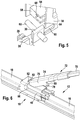
- Fig. 1 a connection element 22 for a right-handed arrangement
- Fig. 2 shows a connection element 22 for a left-handed arrangement of the wiper arm.
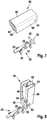
- a connecting device 10 comprises the connecting element 22 and an adapter 34, wherein the adapter 34 may have different designs, as in the Fig. 7 to 16 are shown.
- All adapters in versions 34, 84, 106, 142 have in common that they are at their outer ends the wiper blade 12 end facing a bearing block 54 which is integrally formed on the inside of a side wall 38 and the inside of the opposite side wall 38 forms a gap 64.
- the bearing block 54 Adjacent to the intermediate space, the bearing block 54 has a hub 56 which is open in the assembled state to the bottom 24 of the connection element 22 and which merges into a closed part 58 with a bearing bore 68.
- the two side walls 38 are connected to one another by a cover wall 36.
- the adapter 34 For mounting, e.g. the adapter 34 is rotated by about 90 ° in the direction of the outer end of the wiper blade 12 so that it can be pushed onto the bearing web 30.
- the bearing web 30 penetrates on the inside of a side wall 38 of the adapter 34 slidably into the intermediate space 64, while the bearing pin 62 with its outwardly facing, shorter part in a connection member 22 towards open bearing slot 60 and with its inwardly facing, longer part dips into the open hub 56.
- the adapter 34 can be displaced within the gap 64 in the direction of the outwardly facing part of the bearing pin 62, wherein the inwardly facing part of the bearing pin 62 penetrates into the bearing bore 68 until finally the inside of the bearing web 30 at the opposite end face of the bearing block 54 is present, while the outer end face of the bearing pin 62 in the bearing slot 60 is approximately flush with the outer contour of the adapter 34. If this is now pivoted approximately parallel to the wiper blade 12 in the operating position, the longitudinal web 28 slides with its outer side along the inside of the side wall 38 of the adapter 34, so that the connecting element 22 and thus the wiper blade 12 laterally approximately free of play between the bearing block 54 and the side wall 38 of the adapter 34 is guided.
- the adapter 34 has holding means in the form of two on the side walls 38 on the outside extending guide profiles 40, which pass into a projection 66 and a holding opening 52 and locking elements in the form of two spring bars 42 which are integrally formed on the drive side end side of the side walls 38 and outwardly facing locking cams 44 own.
- the end edge 82 of the connecting element 72 is supported on the projection 66 which serves as a stop, while the lower edge of the side walls 76 rests on the guide profiles 40.
- the locking cams 44 engage in undercuts 80, which are formed by projections 78 on the side walls 76 of the connecting element 72.
- the edges of the undercut 80 come to the stop ramps 46 of the locking cam 44 to the plant.
- the locking cams 44 have adjacent to the abutment slopes 46 stops 48, which extend approximately perpendicular to the longitudinal direction of the adapter 34. They offer further possibilities for latching with corresponding connecting elements of other wiper arms.
- connecting device 10 comprises in addition to the connecting element 22, an adapter 84 for connecting a wiper arm 98 with a hook-shaped end 100. This has on the side of the connecting element 22 toward a wiper arm 98 approximately parallel, short leg 102 with a detent hole 104.
- the adapter 84 has a substantially U-shaped cross-sectional profile, which is formed by side walls 89 and a top wall 88 connecting them together.
- the bearing block 54 In the facing to the outer end of the wiper blade 12 front part 50 is the bearing block 54 with the open hub 56. Further, in the bearing block 54 opposite side wall 89 to the open hub 56 aligned bearing slot 60 is provided.
- a guide block 86 connected to the top wall 88, the interior 94 of which receives the hook-shaped end 100 of the wiper arm 98.
- the width of the intermediate space 96 is matched to the lateral offset between the longitudinal web 28 and the bearing web 30.
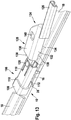
- a further embodiment of the connecting device according to the invention show the Fig. 11 to Fig. 13 , It comprises the connection element 22 and an adapter 106, in which the bearing block 54 with the open hub 56 is accommodated in a front part 108. In a side wall 116 of the front part 108, the bearing block 60 is provided in alignment with the open hub 56.
- the adapter 106 is guided laterally as in the previous embodiments by the bearing web 30 and the longitudinal web 28 approximately free of play.
- a matching connector 124 which is connected via a connection profile 126 with a wiper arm, is pushed by the inner end of the wiper blade 12 on the adapter 106, wherein the spring tongue 118 is pressed with the key 120 from a top wall 130 of a guide profile 128 inwardly while Guide ribs 134 on the side walls 132 of the guide profile 128 under the free edges of the side walls 116 of the adapter 106 engage.
- the end edge 138 of the guide profile 128 abuts the shoulder 110 of the adapter 106, wherein the heel 110 in the longitudinal direction subsequent guide edges 112 in recesses 136 on the side walls 132 of the guide profile 128 insert and the key 120 in a detent hole in the Top wall 130 of the guide profile 128 engages.
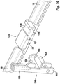
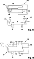
- FIGS. 14 to 16 a variant is shown in which the wiper arm or its connecting element 156 is connected to the sidelock principle with the wiper blade 12.
- the adapter 142 provided for this purpose has a profile which is U-shaped in cross-section and is formed by two side walls 146 and a cover wall 144.
- a guide block 54 is provided with an open hub 56 and a bearing bore 68 formed on one side wall 146, while the other side wall 146, in which Lagerkulisse 60 is provided, a gap 64 is released for the bearing bar 30.
- a recess 148 extending transversely to the longitudinal direction is provided, which opens into a recess 154 on the side wall 146 facing away from the opening 152.
- the connecting element 156 has a connection profile 158 for a wiper arm, not shown.
- a pin 162 is riveted into the leg. The pin extends transversely to the longitudinal direction and is inserted during assembly in the opening 152 and the subsequent receiving sleeve 150, while the connecting element 156 is in an assembly about 90 ° to the longitudinal direction of the wiper blade 12. If the connecting element 156 is then pivoted into an operating position approximately parallel to the wiper blade 12, a bridge 164 engages over the adapter 142 and engages with its angled end 166 in the niche 154.
- the angled end 166 forms with the bridge 164 a slightly smaller angle than 90 ° so that it locks into niche 154.
- the bridge 164 In the engaged position, the bridge 164 is located in the recess 148.
- the connecting element 156 In the operating position, the connecting element 156 is able to perform a pivoting movement relative to the connecting element 22 with the adapter 142.
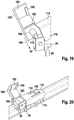
- connection device 10 comprises a connection element 170 and an adapter 168.
- the connection element 170 is designed as a sheet metal claw and has like the connection element 22 a bottom 24 with laterally arranged claws 26.
- a similar bearing web 30 is formed as on the connection element 22. This carries an inwardly directed, freely bearing Lagerpin 172.
- a guide wall 176 is arranged, which is diametrically opposite the bearing bar 30 and carries an inwardly directed, cantilevered guide shaft 174.
- the guide wall 176 and the guide shaft 174 have the same dimensions as the bearing bar 30 and the bearing pin 172, so that they are suitable for a right-handed or left-handed mounting of the adapter 168 as needed, with a change of Wischarmanowski the function between the bearing bar 30 and guide wall 176 changes, so that the former bearing bar 30 performs the function of the former guide wall 176 after the change.
- the adapter 168 has a substantially U-shaped profile formed by a top wall 114 and two side walls 116 which has a front portion 108 in which a hub 186 for receiving the bearing pin 172 is housed.
- the hub 186 is formed with an end face on an inner side of a side wall 116 of the adapter 168, while the other end face is open.
- the open side is covered by a flap 180 which is connected to the side wall 116 at the closed side of the hub 186 by a living hinge 182. With open flap 180, the adapter 168 can be pushed in the direction of the arrows 184 on the bearing pin 172.
- the flap 180 When the flap 180 is closed, the latter overlaps the bearing web 30 and preferably rests against the outside of the bearing web 30 via a rim 190, while the end face of the hub 186 is supported on the inside of the bearing web 30 in the direction of the arrows 184.
- the flap 180 Towards the outer end of the wiper blade 12, the flap 180 has a rudimentary end wall 188.
- the adapter 168 has a guide block 192 with a link 196 open towards the connecting element 170.
- the guide block 192 forms a gap 194 with a side wall 116.
- the outer contour of the adapter 168 is similar to the outer contour of the adapter 106.
- the front portion 108 is separated from the remainder of the adapter 168 by a shoulder 110 that laterally merges into longitudinal guide edges 112 on the sidewalls 116.
- a spring tongue 118 is formed by slots 122, which faces the inner end of the wiper blade 12 and at its free end has an outwardly facing button 120.
- the top wall 114 has a bridge-shaped reinforcement 178.
- the connecting element 124 according to Fig. 23 is essentially the same as the post Fig. 13 , It is pushed in the direction of arrows 198 on the adapter 168 until the end edge 138 of the top wall 130 abuts against the shoulder 110.
- the key 120 engages at the end of the spring tongue 118 in a locking hole 140 of the top wall 130 a.
- the essential elements of all embodiments are the bearing bar 30 with the bearing pin 172 and the guide wall 176 with the guide axis 174 and the hub 186, the flap 180 and the guide block 192 with the link 196 and the gap 194.
- the remaining features of the adapter can depending on Use case of the configuration of the respective wiper arm or a connecting element can be adjusted. Also, adapters are possible which unite various holding means and locking means in one embodiment, so that the same adapter is suitable for several different wiper arms.
Landscapes
- Engineering & Computer Science (AREA)
- Mechanical Engineering (AREA)
- Cleaning Implements For Floors, Carpets, Furniture, Walls, And The Like (AREA)
Claims (8)
- Dispositif de raccordement (10) pour la connexion articulée d'un bras d'essuie-glace (70, 72, 98, 100, 124, 156) à un balai d'essuie-glace (12) qui peut être connecté fixement à un élément de raccordement (22, 170) du dispositif de raccordement (10), qui possède au moins une nervure de palier (30) s'étendant dans la direction longitudinale, qui pénètre à l'intérieur d'un adaptateur (34, 84, 106, 142, 168) du dispositif de raccordement (10) et qui porte une goupille de palier (62, 172) s'étendant transversalement à la direction longitudinale, sur laquelle l'adaptateur (34, 84, 106, 142, 168) est supporté de manière pivotante par des moyens de palier (54, 60, 186), l'adaptateur (34, 84, 106, 142, 168) possédant des moyens d'encliquetage (42, 44, 90, 118, 120, 154, 166) et des moyens de retenue (40, 52, 110, 112, 150, 152, 164, 192, 196) pour la connexion amovible au bras d'essuie-glace (70, 72, 98, 100, 124, 156), caractérisé en ce que la nervure de palier (30) est façonnée au niveau d'un côté longitudinal d'un fonds (24) seulement dans une courte région à l'extrémité de l'élément de raccordement (22, 170) et en ce que l'élément de raccordement (22) présente une nervure longitudinale (28) décalée dans la direction longitudinale par rapport à la nervure de palier (30) sur le même côté longitudinal, laquelle s'étend de manière décalée vers l'extérieur par rapport à la nervure de palier (30) dans une mesure telle que dans l'état monté, le côté extérieur de la nervure longitudinale (28) soit guidé contre le côté intérieur d'une paroi latérale (38, 89, 116, 146) de l'adaptateur (34, 84, 106, 142), tandis que le côté intérieur de la nervure de palier (30) est guidé contre le côté tourné vers elle d'un bloc palier (54) de l'adaptateur (34, 84, 106, 142).
- Dispositif de raccordement (10) selon la revendication 1, caractérisé en ce que la goupille de palier (62) s'étend des deux côtés de la nervure de palier (30) et la partie de la goupille de palier (62) tournée vers l'intérieur est plus longue que la partie de la goupille de palier (62) tournée vers l'extérieur.
- Dispositif de raccordement (10) selon la revendication 2, caractérisé en ce que lors du montage de l'adaptateur (34, 84, 106, 142) dans une position pivotée à 90 degrés par rapport à la direction longitudinale du balai d'essuie-glace (12), la partie de la goupille de palier (62) tournée vers l'intérieur peut être poussée dans la direction longitudinale du balai d'essuie-glace (12) dans un moyeu ouvert (56) du bloc palier (54), tandis que le côté extérieur de la nervure de palier (30) glisse le long du côté intérieur de la paroi latérale (38, 89, 116, 146) de l'adaptateur (34, 84, 106, 142) et la partie de la goupille de palier (62) tournée vers l'extérieur est guidée dans une coulisse de palier ouverte (60) de la paroi latérale (38, 89, 116, 146) jusqu'à ce qu'une partie fermée (58) du moyeu puisse être poussée avec son alésage de palier (68) sur la goupille de palier (62).
- Dispositif de raccordement (10) selon la revendication 3, caractérisé en ce que le côté frontal de la partie de la goupille de palier (62) tournée vers l'extérieur se termine, dans l'état monté, en affleurement avec le contour extérieur de l'adaptateur (34, 84, 106, 142).
- Dispositif de raccordement (10) selon l'une quelconque des revendications précédentes, caractérisé en ce que les moyens de palier de l'adaptateur (34, 84, 106, 142), à savoir le bloc palier (54) avec le moyeu ouvert (56) ainsi qu'avec l'alésage de palier (68) et la coulisse de palier (60) sont disposés dans une partie frontale (50) de l'adaptateur (34, 84, 106, 142) tournée vers l'extrémité libre du balai d'essuie-glace (12).
- Dispositif de raccordement (10) selon l'une quelconque des revendications précédentes, caractérisé en ce que l'élément de raccordement (22, 170) est réalisé en métal sous forme de griffes en tôle, dont les crochets (26) formés au niveau d'un fond (24) sont soudés à l'élément de support (16) sous la forme d'au moins un rail à ressort.
- Dispositif de raccordement (10) selon la revendication 6, caractérisé en ce que l'épaisseur de matériau de la nervure de palier (30) dans la région de la goupille de palier (62, 172) est renforcée par pliage de 180 degrés.
- Balai d'essuie-glace (12) caractérisé par un dispositif de raccordement (10) connecté à celui-ci, selon l'une quelconque des revendications précédentes.
Priority Applications (1)
| Application Number | Priority Date | Filing Date | Title |
|---|---|---|---|
| PL11702015T PL2552755T3 (pl) | 2010-03-29 | 2011-01-31 | Urządzenie przyłączeniowe do przegubowego połączenia ramienia wycieraczki z piórem wycieraczki |
Applications Claiming Priority (2)
| Application Number | Priority Date | Filing Date | Title |
|---|---|---|---|
| DE201010003372 DE102010003372A1 (de) | 2010-03-29 | 2010-03-29 | Anschlussvorrichtung zum gelenkigen Verbinden eines Wischarms mit einem Wischblatt |
| PCT/EP2011/051286 WO2011120723A1 (fr) | 2010-03-29 | 2011-01-31 | Dispositif d'accouplement pour l'assemblage articulé d'un bras d'essuie-glace avec un balai d'essuie-glace |
Publications (2)
| Publication Number | Publication Date |
|---|---|
| EP2552755A1 EP2552755A1 (fr) | 2013-02-06 |
| EP2552755B1 true EP2552755B1 (fr) | 2017-11-29 |
Family
ID=43640666
Family Applications (1)
| Application Number | Title | Priority Date | Filing Date |
|---|---|---|---|
| EP11702015.6A Active EP2552755B1 (fr) | 2010-03-29 | 2011-01-31 | Dispositif d'accouplement pour l'assemblage articulé d'un bras d'essuie-glace avec un balai d'essuie-glace |
Country Status (4)
| Country | Link |
|---|---|
| EP (1) | EP2552755B1 (fr) |
| DE (1) | DE102010003372A1 (fr) |
| PL (1) | PL2552755T3 (fr) |
| WO (1) | WO2011120723A1 (fr) |
Families Citing this family (18)
| Publication number | Priority date | Publication date | Assignee | Title |
|---|---|---|---|---|
| DE102010030880A1 (de) * | 2010-07-02 | 2012-01-05 | Robert Bosch Gmbh | Anschlussvorrichtung zum gelenkigen Verbinden eines Wischarms mit einem Wischblatt |
| US9174609B2 (en) | 2011-04-21 | 2015-11-03 | Pylon Manufacturing Corp. | Wiper blade with cover |
| US9457768B2 (en) | 2011-04-21 | 2016-10-04 | Pylon Manufacturing Corp. | Vortex damping wiper blade |
| MX345011B (es) | 2011-07-28 | 2017-01-11 | Pylon Mfg Corp | Adaptador, conector y conjunto de limpiaparabrisas. |
| US9108595B2 (en) | 2011-07-29 | 2015-08-18 | Pylon Manufacturing Corporation | Windshield wiper connector |
| DE102011057118A1 (de) * | 2011-12-29 | 2013-07-04 | Valeo Systèmes d'Essuyage | Wischvorrichtung zum Reinigen von Fahrzeugscheiben |
| RU2577981C1 (ru) | 2012-02-24 | 2016-03-20 | Пилон Мануфэкчуринг Корп. | Щетка стеклоочистителя |
| US20130219649A1 (en) | 2012-02-24 | 2013-08-29 | Pylon Manufacturing Corp. | Wiper blade |
| CN104349950A (zh) * | 2012-06-13 | 2015-02-11 | 罗伯特·博世有限公司 | 刮水片适配器系统 |
| US10829092B2 (en) | 2012-09-24 | 2020-11-10 | Pylon Manufacturing Corp. | Wiper blade with modular mounting base |
| US10166951B2 (en) | 2013-03-15 | 2019-01-01 | Pylon Manufacturing Corp. | Windshield wiper connector |
| US9505380B2 (en) | 2014-03-07 | 2016-11-29 | Pylon Manufacturing Corp. | Windshield wiper connector and assembly |
| USD777079S1 (en) | 2014-10-03 | 2017-01-24 | Pylon Manufacturing Corp. | Wiper blade frame |
| CN104309579B (zh) * | 2014-10-31 | 2016-10-12 | 成都众易通科技有限公司 | 一种汽车挡风玻璃清洁装置 |
| FR3043616B1 (fr) * | 2015-11-13 | 2017-12-15 | Valeo Systemes Dessuyage | Organe pour un systeme de connexion d’un balai d’essuie-glace a un bras d’entrainement |
| RU195049U1 (ru) * | 2019-09-23 | 2020-01-14 | Открытое акционерное общество "Промышленно-коммерческая фирма "Хорс" | Щетка стеклоочистителя |
| RU195194U1 (ru) * | 2019-09-23 | 2020-01-17 | Открытое акционерное общество "Промышленно-коммерческая фирма "Хорс" | Устройство для съемного соединения щетки стеклоочистителя с рычагом стеклоочистителя |
| FR3113014B1 (fr) * | 2020-07-30 | 2022-10-28 | Valeo Systemes Dessuyage | Dispositif de connexion pour un système d’essuyage pour un véhicule |
Family Cites Families (8)
| Publication number | Priority date | Publication date | Assignee | Title |
|---|---|---|---|---|
| DE10160111A1 (de) * | 2001-12-07 | 2003-07-03 | Volkswagen Ag | Anschlussvorrichtung für ein Wischerblatt am Wischerarm einer Scheibenwischeranlage |
| JP4131913B2 (ja) * | 2002-04-17 | 2008-08-13 | 日本ワイパブレード株式会社 | ワイパーブレード用の連結部材 |
| DE10347637A1 (de) | 2003-10-09 | 2005-05-12 | Bosch Gmbh Robert | Vorrichtung zum Verbinden eines Wischblatts mit einem Wischerarm sowie ein Wischblatt, einen Wischerarm und ein entsprechendes Verbindungsstück |
| FR2879986B1 (fr) | 2004-12-23 | 2008-07-11 | Valeo Systemes Dessuyage | Balai d'essuie-glace plat universel et connecteur amovible associe |
| DE102005020601A1 (de) * | 2005-05-03 | 2006-11-16 | Robert Bosch Gmbh | Vorrichtung zum gelenkigen Verbinden eines Wischblatts mit einem Wischarm |
| DE102005062462B4 (de) * | 2005-12-27 | 2020-08-06 | Robert Bosch Gmbh | Wischblatt |
| DE102007022185B4 (de) * | 2007-02-19 | 2018-12-13 | Robert Bosch Gmbh | Verbindungselement zum gelenkigen Verbinden eines Wischblatts mit einem Wischarm |
| DE102007021333A1 (de) * | 2007-05-07 | 2008-11-13 | Robert Bosch Gmbh | Anschlussvorrichtung zum gelenkigen Verbinden eines Wischblatts mit einem Wischarm |
-
2010
- 2010-03-29 DE DE201010003372 patent/DE102010003372A1/de not_active Ceased
-
2011
- 2011-01-31 EP EP11702015.6A patent/EP2552755B1/fr active Active
- 2011-01-31 WO PCT/EP2011/051286 patent/WO2011120723A1/fr not_active Ceased
- 2011-01-31 PL PL11702015T patent/PL2552755T3/pl unknown
Also Published As
| Publication number | Publication date |
|---|---|
| DE102010003372A1 (de) | 2011-09-29 |
| WO2011120723A1 (fr) | 2011-10-06 |
| EP2552755A1 (fr) | 2013-02-06 |
| PL2552755T3 (pl) | 2018-04-30 |
Similar Documents
| Publication | Publication Date | Title |
|---|---|---|
| WO2011120723A1 (fr) | Dispositif d'accouplement pour l'assemblage articulé d'un bras d'essuie-glace avec un balai d'essuie-glace | |
| EP2146877B1 (fr) | Dispositif de connexion pour la connexion articulee d'un balai d'essuie-glace a un bras d'essuie-glace | |
| EP2588352B1 (fr) | Dispositif de raccordement destiné à relier de manière articulée un bras d'essuie-glace à un balai d'essuie-glace | |
| EP2424755B1 (fr) | Dispositif de raccordement, destine a relier de maniere articulee un element de liaison solidaire d'un bras d'essuie-glace | |
| EP2326538B1 (fr) | Dispositif de raccordement permettant de realiser une liaison articulee entre un balai d'essuie-glace et un bras d'essuie-glace | |
| EP2321160B1 (fr) | Dispositif de liaison articulée entre un balai d essuie-glace et un bras d essuie-glace | |
| EP1868860B1 (fr) | Dispositif pour relier de façon articulee un balai d'essuie-glace a un bras d'essuie-glace | |
| EP1846274B1 (fr) | Dispositif pour relier de facon articulee un balai d'essuie-glace a un bras d'essuie-glace d'un systeme d'essuie-glace | |
| EP2229301B1 (fr) | Balai d'essuie-glace | |
| EP2501591B1 (fr) | Adaptateur pour raccorder un élément de raccordement, situé à l'extrémité d'un bras d'essuie-glace, à un balai d'essuie-glace, en particulier de structure à barre plate | |
| EP2254777B1 (fr) | Dispositif de raccordement articulé d'une raclette | |
| EP2113432B2 (fr) | Essuie-glace, en particulier pour véhicules automobiles | |
| EP2127969B1 (fr) | Raclette d'essuie-glace | |
| DE102010003269A1 (de) | Adapter zum gelenkigen Verbinden eines Verbindungselements am Ende eines Wischarms mit einem Anschlusselement eines Wischblatts | |
| EP2142404A1 (fr) | Dispositif de liaison | |
| WO2011042518A1 (fr) | Balai d'essuie-glace | |
| EP2331373B1 (fr) | Dispositif d'assemblage pour la liaison articulée d'un balai d'essuie-glace | |
| EP2179901B1 (fr) | Dispositif de raccordement pour la liaison articulée d'une lame d'essuyage conçue sous la forme d'une barre plate avec un bras d'essuyage | |
| EP2271525A1 (fr) | Dispositif de liaison articulée d une raclette d essuie-glace avec un bras d essuie-glace |
Legal Events
| Date | Code | Title | Description |
|---|---|---|---|
| PUAI | Public reference made under article 153(3) epc to a published international application that has entered the european phase |
Free format text: ORIGINAL CODE: 0009012 |
|
| 17P | Request for examination filed |
Effective date: 20121029 |
|
| AK | Designated contracting states |
Kind code of ref document: A1 Designated state(s): AL AT BE BG CH CY CZ DE DK EE ES FI FR GB GR HR HU IE IS IT LI LT LU LV MC MK MT NL NO PL PT RO RS SE SI SK SM TR |
|
| DAX | Request for extension of the european patent (deleted) | ||
| 17Q | First examination report despatched |
Effective date: 20140514 |
|
| GRAP | Despatch of communication of intention to grant a patent |
Free format text: ORIGINAL CODE: EPIDOSNIGR1 |
|
| INTG | Intention to grant announced |
Effective date: 20170608 |
|
| GRAS | Grant fee paid |
Free format text: ORIGINAL CODE: EPIDOSNIGR3 |
|
| GRAA | (expected) grant |
Free format text: ORIGINAL CODE: 0009210 |
|
| AK | Designated contracting states |
Kind code of ref document: B1 Designated state(s): AL AT BE BG CH CY CZ DE DK EE ES FI FR GB GR HR HU IE IS IT LI LT LU LV MC MK MT NL NO PL PT RO RS SE SI SK SM TR |
|
| REG | Reference to a national code |
Ref country code: CH Ref legal event code: EP |
|
| REG | Reference to a national code |
Ref country code: AT Ref legal event code: REF Ref document number: 950070 Country of ref document: AT Kind code of ref document: T Effective date: 20171215 |
|
| REG | Reference to a national code |
Ref country code: IE Ref legal event code: FG4D Free format text: LANGUAGE OF EP DOCUMENT: GERMAN |
|
| REG | Reference to a national code |
Ref country code: DE Ref legal event code: R096 Ref document number: 502011013353 Country of ref document: DE |
|
| REG | Reference to a national code |
Ref country code: FR Ref legal event code: PLFP Year of fee payment: 8 |
|
| REG | Reference to a national code |
Ref country code: NL Ref legal event code: MP Effective date: 20171129 |
|
| REG | Reference to a national code |
Ref country code: LT Ref legal event code: MG4D |
|
| PG25 | Lapsed in a contracting state [announced via postgrant information from national office to epo] |
Ref country code: FI Free format text: LAPSE BECAUSE OF FAILURE TO SUBMIT A TRANSLATION OF THE DESCRIPTION OR TO PAY THE FEE WITHIN THE PRESCRIBED TIME-LIMIT Effective date: 20171129 Ref country code: LT Free format text: LAPSE BECAUSE OF FAILURE TO SUBMIT A TRANSLATION OF THE DESCRIPTION OR TO PAY THE FEE WITHIN THE PRESCRIBED TIME-LIMIT Effective date: 20171129 Ref country code: SE Free format text: LAPSE BECAUSE OF FAILURE TO SUBMIT A TRANSLATION OF THE DESCRIPTION OR TO PAY THE FEE WITHIN THE PRESCRIBED TIME-LIMIT Effective date: 20171129 Ref country code: NO Free format text: LAPSE BECAUSE OF FAILURE TO SUBMIT A TRANSLATION OF THE DESCRIPTION OR TO PAY THE FEE WITHIN THE PRESCRIBED TIME-LIMIT Effective date: 20180228 Ref country code: ES Free format text: LAPSE BECAUSE OF FAILURE TO SUBMIT A TRANSLATION OF THE DESCRIPTION OR TO PAY THE FEE WITHIN THE PRESCRIBED TIME-LIMIT Effective date: 20171129 |
|
| PG25 | Lapsed in a contracting state [announced via postgrant information from national office to epo] |
Ref country code: GR Free format text: LAPSE BECAUSE OF FAILURE TO SUBMIT A TRANSLATION OF THE DESCRIPTION OR TO PAY THE FEE WITHIN THE PRESCRIBED TIME-LIMIT Effective date: 20180301 Ref country code: HR Free format text: LAPSE BECAUSE OF FAILURE TO SUBMIT A TRANSLATION OF THE DESCRIPTION OR TO PAY THE FEE WITHIN THE PRESCRIBED TIME-LIMIT Effective date: 20171129 Ref country code: RS Free format text: LAPSE BECAUSE OF FAILURE TO SUBMIT A TRANSLATION OF THE DESCRIPTION OR TO PAY THE FEE WITHIN THE PRESCRIBED TIME-LIMIT Effective date: 20171129 Ref country code: BG Free format text: LAPSE BECAUSE OF FAILURE TO SUBMIT A TRANSLATION OF THE DESCRIPTION OR TO PAY THE FEE WITHIN THE PRESCRIBED TIME-LIMIT Effective date: 20180228 Ref country code: LV Free format text: LAPSE BECAUSE OF FAILURE TO SUBMIT A TRANSLATION OF THE DESCRIPTION OR TO PAY THE FEE WITHIN THE PRESCRIBED TIME-LIMIT Effective date: 20171129 |
|
| PG25 | Lapsed in a contracting state [announced via postgrant information from national office to epo] |
Ref country code: NL Free format text: LAPSE BECAUSE OF FAILURE TO SUBMIT A TRANSLATION OF THE DESCRIPTION OR TO PAY THE FEE WITHIN THE PRESCRIBED TIME-LIMIT Effective date: 20171129 |
|
| PG25 | Lapsed in a contracting state [announced via postgrant information from national office to epo] |
Ref country code: CZ Free format text: LAPSE BECAUSE OF FAILURE TO SUBMIT A TRANSLATION OF THE DESCRIPTION OR TO PAY THE FEE WITHIN THE PRESCRIBED TIME-LIMIT Effective date: 20171129 Ref country code: CY Free format text: LAPSE BECAUSE OF FAILURE TO SUBMIT A TRANSLATION OF THE DESCRIPTION OR TO PAY THE FEE WITHIN THE PRESCRIBED TIME-LIMIT Effective date: 20171129 Ref country code: EE Free format text: LAPSE BECAUSE OF FAILURE TO SUBMIT A TRANSLATION OF THE DESCRIPTION OR TO PAY THE FEE WITHIN THE PRESCRIBED TIME-LIMIT Effective date: 20171129 Ref country code: SK Free format text: LAPSE BECAUSE OF FAILURE TO SUBMIT A TRANSLATION OF THE DESCRIPTION OR TO PAY THE FEE WITHIN THE PRESCRIBED TIME-LIMIT Effective date: 20171129 Ref country code: DK Free format text: LAPSE BECAUSE OF FAILURE TO SUBMIT A TRANSLATION OF THE DESCRIPTION OR TO PAY THE FEE WITHIN THE PRESCRIBED TIME-LIMIT Effective date: 20171129 |
|
| REG | Reference to a national code |
Ref country code: DE Ref legal event code: R097 Ref document number: 502011013353 Country of ref document: DE |
|
| PG25 | Lapsed in a contracting state [announced via postgrant information from national office to epo] |
Ref country code: RO Free format text: LAPSE BECAUSE OF FAILURE TO SUBMIT A TRANSLATION OF THE DESCRIPTION OR TO PAY THE FEE WITHIN THE PRESCRIBED TIME-LIMIT Effective date: 20171129 Ref country code: SM Free format text: LAPSE BECAUSE OF FAILURE TO SUBMIT A TRANSLATION OF THE DESCRIPTION OR TO PAY THE FEE WITHIN THE PRESCRIBED TIME-LIMIT Effective date: 20171129 Ref country code: IT Free format text: LAPSE BECAUSE OF FAILURE TO SUBMIT A TRANSLATION OF THE DESCRIPTION OR TO PAY THE FEE WITHIN THE PRESCRIBED TIME-LIMIT Effective date: 20171129 |
|
| REG | Reference to a national code |
Ref country code: CH Ref legal event code: PL |
|
| PG25 | Lapsed in a contracting state [announced via postgrant information from national office to epo] |
Ref country code: MT Free format text: LAPSE BECAUSE OF FAILURE TO SUBMIT A TRANSLATION OF THE DESCRIPTION OR TO PAY THE FEE WITHIN THE PRESCRIBED TIME-LIMIT Effective date: 20171129 |
|
| PLBE | No opposition filed within time limit |
Free format text: ORIGINAL CODE: 0009261 |
|
| STAA | Information on the status of an ep patent application or granted ep patent |
Free format text: STATUS: NO OPPOSITION FILED WITHIN TIME LIMIT |
|
| GBPC | Gb: european patent ceased through non-payment of renewal fee |
Effective date: 20180228 |
|
| PG25 | Lapsed in a contracting state [announced via postgrant information from national office to epo] |
Ref country code: LU Free format text: LAPSE BECAUSE OF NON-PAYMENT OF DUE FEES Effective date: 20180131 |
|
| REG | Reference to a national code |
Ref country code: IE Ref legal event code: MM4A |
|
| 26N | No opposition filed |
Effective date: 20180830 |
|
| PG25 | Lapsed in a contracting state [announced via postgrant information from national office to epo] |
Ref country code: SI Free format text: LAPSE BECAUSE OF FAILURE TO SUBMIT A TRANSLATION OF THE DESCRIPTION OR TO PAY THE FEE WITHIN THE PRESCRIBED TIME-LIMIT Effective date: 20171129 Ref country code: LI Free format text: LAPSE BECAUSE OF NON-PAYMENT OF DUE FEES Effective date: 20180131 Ref country code: CH Free format text: LAPSE BECAUSE OF NON-PAYMENT OF DUE FEES Effective date: 20180131 |
|
| PG25 | Lapsed in a contracting state [announced via postgrant information from national office to epo] |
Ref country code: IE Free format text: LAPSE BECAUSE OF NON-PAYMENT OF DUE FEES Effective date: 20180131 |
|
| PG25 | Lapsed in a contracting state [announced via postgrant information from national office to epo] |
Ref country code: GB Free format text: LAPSE BECAUSE OF NON-PAYMENT OF DUE FEES Effective date: 20180228 |
|
| REG | Reference to a national code |
Ref country code: AT Ref legal event code: MM01 Ref document number: 950070 Country of ref document: AT Kind code of ref document: T Effective date: 20180131 |
|
| PG25 | Lapsed in a contracting state [announced via postgrant information from national office to epo] |
Ref country code: AT Free format text: LAPSE BECAUSE OF NON-PAYMENT OF DUE FEES Effective date: 20180131 |
|
| PG25 | Lapsed in a contracting state [announced via postgrant information from national office to epo] |
Ref country code: MC Free format text: LAPSE BECAUSE OF FAILURE TO SUBMIT A TRANSLATION OF THE DESCRIPTION OR TO PAY THE FEE WITHIN THE PRESCRIBED TIME-LIMIT Effective date: 20171129 |
|
| PG25 | Lapsed in a contracting state [announced via postgrant information from national office to epo] |
Ref country code: TR Free format text: LAPSE BECAUSE OF FAILURE TO SUBMIT A TRANSLATION OF THE DESCRIPTION OR TO PAY THE FEE WITHIN THE PRESCRIBED TIME-LIMIT Effective date: 20171129 |
|
| PGFP | Annual fee paid to national office [announced via postgrant information from national office to epo] |
Ref country code: PL Payment date: 20200122 Year of fee payment: 10 |
|
| PG25 | Lapsed in a contracting state [announced via postgrant information from national office to epo] |
Ref country code: PT Free format text: LAPSE BECAUSE OF FAILURE TO SUBMIT A TRANSLATION OF THE DESCRIPTION OR TO PAY THE FEE WITHIN THE PRESCRIBED TIME-LIMIT Effective date: 20171129 Ref country code: HU Free format text: LAPSE BECAUSE OF FAILURE TO SUBMIT A TRANSLATION OF THE DESCRIPTION OR TO PAY THE FEE WITHIN THE PRESCRIBED TIME-LIMIT; INVALID AB INITIO Effective date: 20110131 |
|
| PG25 | Lapsed in a contracting state [announced via postgrant information from national office to epo] |
Ref country code: MK Free format text: LAPSE BECAUSE OF NON-PAYMENT OF DUE FEES Effective date: 20171129 |
|
| PG25 | Lapsed in a contracting state [announced via postgrant information from national office to epo] |
Ref country code: AL Free format text: LAPSE BECAUSE OF FAILURE TO SUBMIT A TRANSLATION OF THE DESCRIPTION OR TO PAY THE FEE WITHIN THE PRESCRIBED TIME-LIMIT Effective date: 20171129 Ref country code: IS Free format text: LAPSE BECAUSE OF FAILURE TO SUBMIT A TRANSLATION OF THE DESCRIPTION OR TO PAY THE FEE WITHIN THE PRESCRIBED TIME-LIMIT Effective date: 20180329 |
|
| PGFP | Annual fee paid to national office [announced via postgrant information from national office to epo] |
Ref country code: FR Payment date: 20220120 Year of fee payment: 12 Ref country code: BE Payment date: 20220120 Year of fee payment: 12 |
|
| PG25 | Lapsed in a contracting state [announced via postgrant information from national office to epo] |
Ref country code: PL Free format text: LAPSE BECAUSE OF NON-PAYMENT OF DUE FEES Effective date: 20210131 |
|
| REG | Reference to a national code |
Ref country code: BE Ref legal event code: MM Effective date: 20230131 |
|
| PG25 | Lapsed in a contracting state [announced via postgrant information from national office to epo] |
Ref country code: FR Free format text: LAPSE BECAUSE OF NON-PAYMENT OF DUE FEES Effective date: 20230131 Ref country code: BE Free format text: LAPSE BECAUSE OF NON-PAYMENT OF DUE FEES Effective date: 20230131 |
|
| PGFP | Annual fee paid to national office [announced via postgrant information from national office to epo] |
Ref country code: DE Payment date: 20250317 Year of fee payment: 15 |