EP2552801B1 - Verpackung, Verfahren zur Herstellung der Verpackung - Google Patents
Verpackung, Verfahren zur Herstellung der Verpackung Download PDFInfo
- Publication number
- EP2552801B1 EP2552801B1 EP11714088.9A EP11714088A EP2552801B1 EP 2552801 B1 EP2552801 B1 EP 2552801B1 EP 11714088 A EP11714088 A EP 11714088A EP 2552801 B1 EP2552801 B1 EP 2552801B1
- Authority
- EP
- European Patent Office
- Prior art keywords
- tear strip
- longitudinal edge
- weakness
- strip portion
- laminate structure
- Prior art date
- Legal status (The legal status is an assumption and is not a legal conclusion. Google has not performed a legal analysis and makes no representation as to the accuracy of the status listed.)
- Active
Links
Images



Classifications
-
- B—PERFORMING OPERATIONS; TRANSPORTING
- B65—CONVEYING; PACKING; STORING; HANDLING THIN OR FILAMENTARY MATERIAL
- B65D—CONTAINERS FOR STORAGE OR TRANSPORT OF ARTICLES OR MATERIALS, e.g. BAGS, BARRELS, BOTTLES, BOXES, CANS, CARTONS, CRATES, DRUMS, JARS, TANKS, HOPPERS, FORWARDING CONTAINERS; ACCESSORIES, CLOSURES, OR FITTINGS THEREFOR; PACKAGING ELEMENTS; PACKAGES
- B65D65/00—Wrappers or flexible covers; Packaging materials of special type or form
- B65D65/02—Wrappers or flexible covers
- B65D65/22—Details
-
- B—PERFORMING OPERATIONS; TRANSPORTING
- B65—CONVEYING; PACKING; STORING; HANDLING THIN OR FILAMENTARY MATERIAL
- B65D—CONTAINERS FOR STORAGE OR TRANSPORT OF ARTICLES OR MATERIALS, e.g. BAGS, BARRELS, BOTTLES, BOXES, CANS, CARTONS, CRATES, DRUMS, JARS, TANKS, HOPPERS, FORWARDING CONTAINERS; ACCESSORIES, CLOSURES, OR FITTINGS THEREFOR; PACKAGING ELEMENTS; PACKAGES
- B65D75/00—Packages comprising articles or materials partially or wholly enclosed in strips, sheets, blanks, tubes or webs of flexible sheet material, e.g. in folded wrappers
- B65D75/26—Articles or materials wholly enclosed in laminated sheets or wrapper blanks
-
- B—PERFORMING OPERATIONS; TRANSPORTING
- B65—CONVEYING; PACKING; STORING; HANDLING THIN OR FILAMENTARY MATERIAL
- B65B—MACHINES, APPARATUS OR DEVICES FOR, OR METHODS OF, PACKAGING ARTICLES OR MATERIALS; UNPACKING
- B65B11/00—Wrapping, e.g. partially or wholly enclosing, articles or quantities of material, in strips, sheets or blanks, of flexible material
- B65B11/004—Wrapping, e.g. partially or wholly enclosing, articles or quantities of material, in strips, sheets or blanks, of flexible material in blanks, e.g. sheets precut and creased for folding
-
- B—PERFORMING OPERATIONS; TRANSPORTING
- B65—CONVEYING; PACKING; STORING; HANDLING THIN OR FILAMENTARY MATERIAL
- B65D—CONTAINERS FOR STORAGE OR TRANSPORT OF ARTICLES OR MATERIALS, e.g. BAGS, BARRELS, BOTTLES, BOXES, CANS, CARTONS, CRATES, DRUMS, JARS, TANKS, HOPPERS, FORWARDING CONTAINERS; ACCESSORIES, CLOSURES, OR FITTINGS THEREFOR; PACKAGING ELEMENTS; PACKAGES
- B65D75/00—Packages comprising articles or materials partially or wholly enclosed in strips, sheets, blanks, tubes or webs of flexible sheet material, e.g. in folded wrappers
- B65D75/52—Details
- B65D75/58—Opening or contents-removing devices added or incorporated during package manufacture
- B65D75/5827—Tear-lines provided in a wall portion
- B65D75/5833—Tear-lines provided in a wall portion for tearing out a portion of the wall
- B65D75/5844—Tear-lines provided in a wall portion for tearing out a portion of the wall the portion of the wall being a narrow strip, e.g. between lines of weakness
Definitions
- the present invention relates to packaging, and in particular, but not exclusively, to packaging for food and more specifically confectionery products.
- wrappers may be in the form of a length of flat, foldable material having an inner surface directed to the food product and an outer surface.
- the outer surface may be printed on or otherwise be provided with information for the consumer.
- the wrapper is supplied as part of a continuous roll or film of wrappers.
- the material is fed through a machine which folds it about each product or each stack of products in turn so that opposing longitudinal side edges are brought into contact and bonded together to form a longitudinal fin or lap seal.
- the material is usually crimped at either end of the product or stack to form end seals and the material is cut to separate each package from the remainder of the film.
- the seals may be formed using an adhesive to bond the opposing surfaces of the wrapper or by heating the material under pressure so that the opposing surfaces melt and fuse together to form a welded seal.
- the wrapper is folded circumferentially about the stack so that one longitudinal edge of the wrapper overlaps the other longitudinal edge and is held in place by means of adhesive or otherwise bonded to form a longitudinal seal.
- the wrapper is longer than the stack and the protruding ends of the wrapper are folded to form tabs in an overlapping arrangement to close the ends of the packet.
- the end closure tabs can be adhered to one another so that the wrapper forms a sealed packet for the products.
- This type of packaging is used for a variety of consumable products such as biscuits and confectionery items including gum pellets, mints, gums, hard boiled sweets, candies, chocolates, toffee and the like.
- a problem with the known wrappers is that the material used is typically quite tough. This makes opening the packet difficult as the material does not easily tear in a controlled fashion.
- tear guide comprises a separate strip of material which is attached to an inner surface of the wrapper.
- the strip is made of a material which is stronger than the wrapper and an end of the strip is exposed in the finished packet so that it can be grasped by a user and pulled to tear the wrapper along the line of the strip.
- Use of a separate tear strip is disadvantageous as it requires the manufacture and storage of an additional component, i.e. the strip, as well as an additional process step of applying the strip to the wrapper.
- packets are formed from a roll of material in a continuous process, such as with flow-wrapped packets, the strip of material is often applied to the material as part of the packaging process.
- the machinery in order to apply the strip, the machinery must be run at speeds which are significantly lower than the maximum speed that could otherwise be achieved. This is especially so where the strip is applied in a transverse direction of the material. This reduces the efficiency of the packaging process and so leads to an increase in costs.
- a package assembly comprising one or more products and a packet enclosing the one or more products, the packet being formed from a laminated material having an outer laminate structure and an inner laminate structure, the packet having an opening arrangement comprising a tear strip formed in the laminated material, the tear strip having an outer tear strip portion defined in the outer laminate structure between a pair of outer spaced lines of weakness in the outer laminate structure and at least one inner line of weakness in the inner laminate structure which is offset from the outer lines of weakness, at least part of the tear strip defined in one of the outer and inner laminate structures being bonded to an overlapping region of the other of the outer and inner laminate structures in a peelable manner.
- the material may be a flexible laminated wrapper or film.
- the material may be a laminated board, such as paperboard, cartonboard, cardboard, or the like.
- the at least a part of the tear strip may be bonded to the overlapping region of the inner laminate structure by means of a peelable adhesive.
- the peelable adhesive may be a re-sealable adhesive.
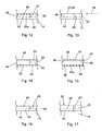
- the opening arrangement comprises only a single inner line of weakness in the inner laminate structure, the inner line of weakness being located between the spaced outer lines of weakness, the outer tear strip portion being bonded to an underlying region of the inner laminate structure in a peelable manner.
- the tear strip comprises an inner tear strip portion defined in the inner laminate structure between two spaced inner lines of weakness in the inner structure.
- Each of the inner lines of weakness substantially follows the path of a corresponding one of the outer lines a weakness and at least one of the inner lines of weakness is offset relative to its corresponding outer line of weakness.
- the outer tear strip portion may be bonded to the inner tear strip portion, in which case the bond strength between the inner outer tear strip portions is stronger than peelable bond between said at least part of the tear strip defined in one of the outer and inner laminate structures and the overlapping region of the other of the outer and inner laminate structures.
- peelable adhesive is used to bond said at least part of the tear strip defined in one of the outer and inner laminate structures and the overlapping region of the other of the outer and inner laminate structures in a peelable manner and a permanent adhesive used to bond the inner and outer laminate structures together elsewhere.
- the inner and outer laminate structures are bonded together using single adhesive, the adhesive being patterned to provide the different required bond strengths.
- the adhesive may be a permanent adhesive, a peelable/resalable adhesive or cold seal.
- the outer tear strip portion may not be bonded to the inner tear strip portion, in which case the outer lines of weakness only extend partway through the outer laminate structure.
- One of the outer and inner tear strip portions may have a longitudinal edge region which projects in a lateral direction of the tear strip beyond a corresponding longitudinal edge of the other of the outer and inner tear strip portions to define a longitudinal edge region which overlaps a portion of one of the outer and inner laminate structures, the longitudinal edge region being bonded to the overlapping portion of said one of the outer and inner laminate structures in a peelable manner.
- the inner tear strip portion may be narrower than the outer tear strip portion, the outer tear strip portion having at least one longitudinal edge region which projects beyond a corresponding longitudinal edge of the inner tear strip portion, and the at least one longitudinal edge region may be bonded to an underlying portion of the inner laminate structure in a peelable manner. Both longitudinal edges of the outer tear strip portion project may beyond the corresponding longitudinal edges of the inner tear strip portion to define longitudinal edge regions on either side of the tear strip, in which case, both longitudinal edge regions may be bonded to respective underlying portions of the inner laminate structure in a peelable manner.
- the inner tear strip portion may be wider than the outer tear strip portion, the inner tear strip portion having at least one longitudinal edge region which projects beyond a corresponding longitudinal edge of the outer tear strip portion, and the at least one longitudinal edge region may be bonded to an overlying portion of the outer laminate structure in a peelable manner. Both longitudinal edges of the inner tear strip portion may project beyond the corresponding longitudinal edges of the outer tear strip portion to define longitudinal edge regions on either side of the outer tear strip, in which case both longitudinal edge regions may be bonded to respective overlying portions of the outer laminate structure in a peelable manner.
- the inner tear strip portion may be partially offset to one side of the outer tear strip portion so that a longitudinal edge of the outer tear strip portion projects beyond a corresponding longitudinal edge of the inner tear strip along one side of the tear strip to define a longitudinal edge region which is bonded to the underlying portion of the inner laminate structure in a peelable manner, and a longitudinal edge of the inner tear strip portion projects beyond a corresponding longitudinal edge of the outer tear strip along the other side of the tear strip to define a longitudinal edge region which is bonded to the overlying portion of the outer laminate structure in a peelable manner.
- the outer tear strip portion may have a maximum width of no more than 10mm, or no more than 8mm, or no more than 6mm, or no more than 4mm, or no more than 2mm, or no more 1 mm.
- the longitudinal edges of the tear strip may be non-linear.
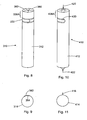
- the packet may form an elongate tube surrounding the one or more products having a longitudinal axis, the tubular packet being closed at either end.
- the tear strip may extend generally in a lateral direction about the tubular packet at a position between the ends.
- the tear strip may encircle the tubular packet completely or partially.
- the tear strip may be positioned proximal to one end of the tubular packet.
- the tear strip may extend generally in a longitudinal direction of the packet.
- the tear strip can be aligned transversely or longitudinally or it can be angled relative to the longitudinal axis of the packet.
- the tear strip can be any desired shaped and may be straight, angled or curved.
- the tear strip can begin and end at any desired positions in the packet.
- the packet may be a flow-wrapped packet.
- the packet may have a longitudinal fin seal or a longitudinal lap seal.
- the ends of the tubular packet may be crimped to form end fin seals or they may be folded to produce overlaying flaps which form end closures.
- the at least one product may be a substantially rigid product which is not able to pass through an opening formed in the packet by removal of the tear strip as such.
- the tear strip may be positioned so that once opened, an end region of the packet can be folded over an end of the product to allow access to the product.
- the product may be generally block shaped.
- the at least one product may at least one confectionery product.
- the at least one confectionery product may be a chocolate or other snack bar.
- the at least one product may comprise a plurality of confectionery products aligned in a stack.
- the confectionery products may be gum pellets, mints, gums, hard boiled sweets, candies, chocolates, toffee and the like.
- a section of laminated material for forming a package comprising an outer laminate structure and an inner laminate structure, the outer and inner laminate structures being bonded together in face to face relation, the section of laminated packaging material having opening arrangement comprising a tear strip defined in the material, the tear strip having an outer tear strip portion defined in the outer laminate structure between two spaced outer lines of weakness in the outer laminate structure and at least one inner line of weakness in the inner laminate structure offset from but following the same general path as the spaced outer lines of weakness, at least part of the tear strip defined in one of the outer and inner laminate structures being bonded to an overlapping region of the other of the outer and inner laminate structures in a peelable manner.
- the opening arrangement comprises only a single inner line of weakness in the inner laminate structure located between the spaced outer lines of weakness, the outer tear strip portion being bonded to the underlying region of the inner laminate structure in a peelable manner.
- the tear strip comprises an inner tear strip portion defined in the inner laminate structure between two spaced inner lines of weakness in the inner structure.
- Each of the inner lines of weakness may substantially following the path of a corresponding one of the outer lines a weakness and at least one of the inner lines of weakness may be offset relative to its corresponding outer line of weakness.
- the outer tear strip portion may be bonded to the inner tear strip portion, in which case the bond strength between the inner and outer tear strip portions is stronger than the peelable bond between said at least part of the tear strip defined in one of the outer and inner laminate structures and the overlapping region of the other of the outer and inner laminate structures.
- a peelable adhesive is used to bond said at least part of the tear strip defined in one of the outer and inner laminate structures and the overlapping region of the other of the outer and inner laminate structures in a peelable manner and a permanent adhesive used to bond the inner and outer laminate structures together where the structures are not intended to be separated.
- the inner and outer laminate structures are bonded with a single adhesive, the adhesive being patterned to provide the different required bond strengths.
- the adhesive may be a permanent adhesive, a peelable/resalable adhesive or cold seal.
- the outer tear strip portion may not be bonded to the inner tear strip portion, in which case the outer lines of weakness only extend partway through the outer laminate structure.
- the inner tear strip portion may be narrower than the outer tear strip portion, the outer tear strip portion having at least one longitudinal edge region which projects beyond a corresponding longitudinal edge of the inner tear strip portion, and the at least one longitudinal edge region may be bonded to an underlying portion of the inner laminate structure in a peelable manner. Both longitudinal edges of the outer tear strip portion may project beyond the corresponding longitudinal edges of the inner tear strip portion to define longitudinal edge regions on either side of the tear strip, in which case both longitudinal edge regions may be bonded to respective underlying portions of the inner laminate structure in a peelable manner.
- the inner tear strip portion may be wider than the outer tear strip portion, the inner tear strip portion having at least one longitudinal edge region which projects beyond a corresponding longitudinal edge of the outer tear strip portion and the at least one longitudinal edge region may be bonded to an overlying portion of the outer laminate structure in a peelable manner. Both longitudinal edges of the inner tear strip portion may project beyond the corresponding longitudinal edges of the outer tear strip portion to define longitudinal edge regions on either side of the tear strip, in which case both longitudinal edge regions may be bonded to respective overlying portions of the outer laminate structure in a peelable manner.
- the inner tear strip portion may be partially offset to one side of the outer tear strip portion so that a longitudinal edge of the outer tear strip portion projects beyond a corresponding longitudinal edge of the inner tear strip along one side of the tear strip to define a first longitudinal edge region and a longitudinal edge of the inner tear strip portion projects beyond a corresponding longitudinal edge of the outer tear strip along the other side of the tear strip to define a second longitudinal edge region, in which case the first longitudinal edge region in the outer laminate structure may be bonded to the underlying portion of the inner laminate structure in a peelable manner whilst the second longitudinal edge region in the inner laminate structure may be bonded to the overlying portion of the outer laminate structure in a peelable manner.
- the outer tear strip portion may have a maximum width of no more than 10mm, or no more than 8mm, or no more than 6mm, or no more than 4mm, or no more than 2mm, or no more 1mm.
- the material may be a laminated board, such as paperboard, cartonboard, cardboard or the like.
- the section of material may be a flexible laminated wrapper which may form part of a continuous length of flexible laminated packaging material having a plurality of opening arrangements defined along its length.
- the continuous length may be formed into a roll.
- the tear strip may extend in any desired direction in the material and may be any desired shape. In one embodiment, the tear strip extends in a generally transverse direction of the section of material across the whole or part of its width.
- a method of manufacturing a package assembly comprising one or more products and a packet enclosing the one or more products, the method comprising:
- the method may also comprise forming the packaging material into a packet enclosing the one or more products.
- the material may be a laminated board, such as paperboard, cartonboard, cardboard or the like.
- the material may be a flexible laminated wrapper and the method may comprise forming a plurality of wrappers in a continuous length.
- the method may comprise forming the wrapper into a packet enclosing the one or more products using flow-wrap techniques.
- the lines of weakness may be produced in the respective outer and inner laminate structures either before or after the structures are bonded together or a combination of the two.
- the method may comprise applying a permanent laminating adhesive and a peelable adhesive to a surface of at least one of the outer and inner laminate structures at appropriate positions for registration with the lines of weakness.
- the method may comprise applying a single adhesive to a surface of at least one of the outer and inner laminate structures and patterning the adhesive in registration with the lines of weakness to form the required range of bond strengths.
- the method comprises producing only a single inner line of weakness in the inner laminate structure located between the spaced outer lines of weakness and bonding the outer tear strip portion to the underlying region of the inner laminate structure in a peelable manner.
- the method comprises producing two spaced inner lines of weakness in the inner structure to define an inner tear strip portion.
- the inner lines of weakness may each substantially follow the path of a corresponding one of the outer lines a weakness, at least one of the inner lines of weakness may be produced in a position that is offset relative to its corresponding outer line of weakness.
- the method may comprise positioning the lines of weakness such that at least one of the outer and inner tear strip portions has a longitudinal edge region which projects in a lateral direction of the tear strip beyond a corresponding longitudinal edge of the other of the outer and inner tear strip portions to define a longitudinal edge region which overlaps a portion of one of the outer and inner laminate structures, the longitudinal edge region being bonded to the overlapping portion of said one of the outer and inner laminate structures in a peelable manner.
- the method may comprise bonding the inner and outer laminate structures together using one or more adhesives and patterning the adhesive such that the outer tear strip portion is not bonded to the inner tear strip portion, and forming the lines of weakness in the outer laminate structure such that only extend part way through the outer laminate structure.
- the method may comprise bonding the inner and outer laminate structures together using one or more adhesives and patterning the adhesives so that the bond strength between the outer and inner tear strip portions is stronger than the bond strength between said longitudinal edge region of one of the inner and outer tear strip portions and the overlapping portion of one of the outer and inner laminate structures.
- the method may comprise bonding the inner and outer laminate structures together over the majority of their opposed surface areas with a permanent laminating adhesive and bonding said longitudinal edge region of one of the inner and outer tear strip portions and the overlapping portion of one of the outer and inner laminate structures with a peelable adhesive.
- the method may comprise bonding the inner and outer laminate structures together using only a single adhesive, the method comprising patterning the adhesive so that the bond strength formed between the inner and outer laminate structures is lower where a peelable bond is required than in regions where the inner and outer laminate structures are not intended to be separated.
Landscapes
- Engineering & Computer Science (AREA)
- Mechanical Engineering (AREA)
- Packages (AREA)
- Wrappers (AREA)
Claims (15)
- Verpackungsanordnung, welche ein oder mehrere Produkte und eine Verpackung aufweist, die das eine oder die mehreren Produkte umschließt, wobei die Verpackung aus einer flexiblen Schichthülle (14) mit einer äußeren Schichtstruktur (26) und einer inneren Schichtstruktur (24) gebildet ist, wobei die Verpackung eine Öffnungsanordnung hat, welche einen Aufziehstreifen (30) aufweist, der in der Hülle gebildet ist, wobei der Aufziehstreifen (30) einen äußeren Aufziehstreifenteil (40) hat, welcher in der äußeren Schichtstruktur (26) zwischen einem Paar von beabstandeten äußeren Schwachstellenlinien (42, 44) in der äußeren Schichtstruktur definiert ist, wobei der Aufziehstreifen ebenfalls mittels mindestens einer inneren Schwachstellenlinie (48, 50) in der inneren Schichtstruktur definiert ist,
dadurch gekennzeichnet,
dass zumindest eine innere Schwachstellenlinie (48, 50) versetzt zu den äußeren Schwachstellenlinien (42, 44) angeordnet ist, dass mindestens ein Teil des Aufziehstreifens dadurch definiert ist, dass eines der inneren und äußeren Schichtstrukturen (24, 26) an einen überlappenden Bereich des anderen der inneren und äußeren Schichtstrukturen (24, 26) abziehbar gebunden ist. - Verpackungsanordnung nach Anspruch 1,
in welcher der mindestens eine Teil des Aufziehstreifens (30) an den überlappenden Bereich des anderen der inneren und äußeren Schichtstrukturen (24, 26) mittels eines abziehbaren Adhäsivs gebunden ist, welches ein wiederverschließbares Adhäsiv sein kann. - Verpackungsanordnung nach einem der Ansprüche 1 oder 2,
in welcher die Öffnungsanordnung nur eine einzelne innere Schwachstellenlinie (48, 50) in der inneren Schichtstruktur (24) aufweist, wobei die innere Schwachstellenlinie zwischen den beabstandeten äußeren Schwachstellenlinien (42, 44) angeordnet ist, wobei der äußere Aufziehstreifenteil an einen darunter liegenden Bereich der inneren Schichtstruktur abziehbar gebunden ist. - Verpackungsanordnung nach einem der Ansprüche 1 oder 2,
in welcher der Aufziehstreifen einen inneren Aufziehstreifenteil (46) aufweist, welcher in der inneren Schichtstruktur, zwischen zwei beabstandeten inneren Schwachstellenlinien (48, 50) in der inneren Struktur, definiert ist. - Verpackungsanordnung nach Anspruch 4,
in welcher der äußere Aufziehstreifenteil (40) an den inneren Aufziehstreifenteil (46) gebunden ist, wobei die Bindewirkung zwischen dem äußeren Aufziehstreifenteil und dem inneren Aufziehstreifenteil stärker ist, als die abziehbare Bindung zwischen dem mindestens einen Teil des Aufziehstreifens, welcher durch einen der äußeren und inneren Schichtstrukturen und einen überlappenden Bereich des anderen der äußeren und inneren Schichtstrukturen definiert ist, oder wobei der äußere Aufziehstreifenteil nicht an den inneren Aufziehstreifenteil gebunden ist, wobei die Schwachstellenlinien in der äußeren Schichtstruktur sich nur teilweise durch die äußere Schichtstruktur erstrecken. - Verpackungsanordnung nach einem der Ansprüche 4 oder 5,
in welcher mindestens eines der äußeren und inneren Aufziehstreifenteile (40, 46) einen longitudinalen Randbereich aufweist, welcher in einer lateralen Richtung des Aufziehstreifens über einen korrespondierenden Rand des anderen der äußeren und inneren Abreißstreifenteile zum Definieren eines longitudinalen Randbereichs hinausragt, welcher einen Teil von einem der äußeren und inneren Schichtstrukturen überlappt, wobei der longitudinale Randbereich an den überlappenden Teil des einen der äußeren und inneren Schichtstrukturen abziehbar gebunden ist. - Verpackungsanordnung nach einem der Ansprüche 4 bis 6,
in welcher der innere Aufziehstreifenteil (46) schmaler als der äußere Aufziehstreifenteil (40) ist, wobei der äußere Aufziehstreifenteil (46) mindestens einen longitudinalen Randbereich hat, welcher über einen korrespondierenden longitudinalen Rand des inneren Aufziehstreifenteils hinausragt, wobei der mindestens eine longitudinale Randbereich an einen darunter liegenden Teil der inneren Schichtstruktur abziehbar gebunden ist, oder wobei der innere Aufziehstreifenteil breiter als der äußere Aufziehstreifenteil ist, wobei der innere Aufziehstreifenteil (46) mindestens einen longitudinalen Randbereich hat, welcher über einen korrespondierend longitudinalen Rand des äußeren Aufziehstreifenteils hinausragt, wobei der mindestens eine longitudinale Randbereich an einen darüber liegenden Teil der äußeren Schichtstruktur abziehbar gebunden ist, oder wobei der innere Aufziehstreifenteil (46) teilweise versetzt zu einer Seite des äußeren Aufziehstreifenteils angeordnet ist, wobei ein longitudinaler Rand des äußeren Aufziehstreifenteils (40) über einen korrespondierenden longitudinalen Rand des inneren Aufziehstreifens entlang einer Seite des Aufziehstreifens hinausragt, wodurch ein longitudinaler Randbereich definiert ist, welcher an den darunter liegenden Teil der inneren Schichtstruktur abziehbar gebunden ist, wobei ein longitudinaler Rand des inneren Aufziehstreifenteils über einen korrespondierenden longitudinalen Rand des äußeren Aufziehstreifens entlang der anderen Seite des Aufziehstreifens hinausragt, wodurch ein longitudinaler Randbereich definiert ist, welcher an den darüber befindlichen Teil der äußeren Schichtstruktur abziehbar gebunden ist. - Verpackungsanordnung nach einem der voranstehenden Ansprüche,
in welcher die Verpackung eine längliche Röhre bildet, welche das eine oder die mehreren Produkte umschließt und eine longitudinale Achse hat, wobei die röhrenförmige Verpackung an beiden Enden verschlossen ist und wobei die Öffnungsanordnung sich in grundsätzlich lateraler Richtung um die röhrenförmige Verpackung an einer Stelle zwischen den Enden erstreckt, wobei sie die röhrenförmige Verpackung ganz oder teilweise umrandet, oder wobei der Aufziehstreifen sich grundsätzlich in einer longitudinalen Richtung der Verpackung erstreckt. - Verfahren zum Herstellen einer Verpackungsanordnung, welche eine oder mehrere Produkte und eine Verpackung aufweist, die das eine oder die mehreren Produkte umschließt, bei welchem,a. eine flexible Schichthülle (14) gebildet wird, welche eine äußere Schichtstruktur (26) und eine innere Schichtstruktur (24) aufweist, die flächig fluchtend zueinander angeordnet sind,b. zwei beabstandete äußeren Schwachstellenlinien (42, 44) in der äußeren Schichtstruktur (26) gebildet werden, wodurch ein äußerer Aufziehstreifenteil (40) definiert wird,c. mindestens eine inneren Schwachstellenlinie (48, 50) in der inneren Schichtstruktur (24) gebildet wird, welche versetzt zu den beabstandeten äußeren Schwachstellenlinien (42, 44), jedoch derselben grundsätzlichen Bahn wie diese folgend, angeordnet ist, undd. mindestens ein Teil des Aufziehstreifens (30), welcher durch einen der äußeren und inneren Schichtstrukturen definiert ist, abziehbar an einen überlappenden Bereich des anderen der äußeren und inneren Schichtstrukturen gebunden wird.
- Verfahren nach Anspruch 9,
wobei das Verfahren das Herstellen nur einer einzelnen inneren Schwachstellenlinie (48, 50) in der inneren Schichtstruktur, welche zwischen den äußeren Schwachstellenlinien angeordnet ist, und das Binden des äußeren Aufziehstreifenteils in abziehbarer Weise an den darunter liegenden Bereich der inneren Schichtstruktur aufweist. - Verfahren nach Anspruch 9,
wobei das Verfahren das Herstellen von zwei beabstandeten inneren Schwachstellenlinien (48, 50) in der inneren Struktur zum Definieren eines inneren Aufziehstreifenteils (46), welche angeordnet sind, so dass mindestens eines der äußeren und inneren Aufziehstreifenteile einen longitudinalen Randbereich hat, welcher in lateraler Richtung des Aufziehstreifens über einen korrespondierenden longitudinalen Rand des anderen der äußeren und inneren Aufziehstreifenteile hinausragt, um einen longitudinalen Randbereich zu definieren, welcher mit einem der äußeren und inneren Schichtstrukturen überlappt, und das Binden des mindestens einen longitudinalen Randbereichs an den überlappenden Teil des einen der äußeren und inneren laminierten Strukturen in abziehbarer Weise aufweist. - Verfahren nach Anspruch 11,
wobei das Verfahren das Verbinden der inneren und äußeren Schichtstrukturen mittels eines oder mehrerer Adhäsive und das Mustern der Adhäsiv(e), so dass der äußere Aufziehstreifenteil (40) nicht an den inneren Aufziehstreifenteil (46) gebunden ist, und das Bilden der Schwachstellenlinien in der äußeren Schichtstruktur aufweist, so dass sich diese nur teilweise durch die äußere Schichtstruktur erstreckt, oder wobei das Verfahren das Verbinden der inneren und äußeren Schichtstrukturen mittels einer oder mehrerer Adhäsive und dem Mustern der Adhäsive aufweist, so dass die Bindungsstärke zwischen des äußeren und inneren Aufziehstreifenteils stärker ist als die Bindungsstärke des longitudinalen Randbereichs des einen der inneren und äußeren Abreißstreifenteile und dem überlappenden Teil des einen der äußeren und inneren Schichtstrukturen, oder wobei das Verfahren das Verbinden der inneren und äußeren Schichtstrukturen über den Großteil ihrer Flächen mit einem dauerhaft klebenden Adhäsiv und das Binden des longitudinalen Randbereichs eines der inneren und äußeren Abreißstreifenteile und des überlappenden Teils von einer der äußeren und inneren Schichtstrukturen mit einem abziehbaren Adhäsiv, aufweist, oder wobei das Verfahren das Verbinden der inneren und äußeren Schichtstrukturen mittels nur eines einzelnen Adhäsivs aufweist, wobei das Verfahren das Mustern des Adhäsivs aufweist, so dass die Bindungsstärke dort zwischen der inneren und äußeren Schichtstruktur geringer ist, wo eine abziehbare Bindung benötigt wird, als in Bereichen, in denen die inneren und äußeren Schichtstrukturen nicht beabsichtigt sind, voneinander trennbar zu sein. - Verfahren nach einem der Ansprüche 10 bis 12,
wobei das Verfahren das Ausbilden der Schwachstellenlinien, so dass die Beabstandung zwischen den inneren Schwachstellenlinien (48, 50) geringer ist als die Beabstandung zwischen den äußeren Schwachstellenlinien (42, 44), so dass der innere Aufziehstreifenteil (46) schmaler ist als der äußere Abreißstreifenteil (40), wobei der äußere Aufziehstreifenteil mindestens einen longitudinalen Randbereich hat, welcher über einen korrespondierenden longitudinalen Rand des inneren Aufziehstreifenteils hinausragt, und das Binden des mindestens einen longitudinalen Randbereichs des äußeren Aufziehstreifenteils an einem darunter liegenden Teil der inneren Schichtstruktur in abziehbarer Weise aufweist, oder wobei das Verfahren das Ausbilden der Schwachstellenlinien, so dass die Beabstandung zwischen den inneren Schwachstellenlinien größer ist als die Beabstandung zwischen den äußeren Schwachstellenlinien, so dass der innere Aufziehstreifenteil breiter ist als der äußere Aufziehstreifenteil, wobei der innere Aufziehstreifenteil mindestens einen longitudinalen Randbereich hat, welcher über einen korrespondierenden longitudinalen Rand des äußeren Abreißstreifenteils hinausragt, und das Binden des mindestens einen longitudinalen Randbereichs der inneren Schichtstruktur an einen darüber liegenden Teil der äußeren Schichtstruktur in abziehbarer Weise aufweist, oder wobei das Verfahren das Ausbilden der Schwachstellenlinien, so dass der innere Aufziehstreifenteil (46) teilweise versetzt zu einer Seite des äußeren Aufziehstreifenteils (40) angeordnet ist, wobei ein longitudinaler Rand des äußeren Aufziehstreifenteils über einen korrespondierenden longitudinalen Rand des inneren Aufziehstreifens entlang einer Seite des Aufziehstreifens übersteht, wobei ein erster longitudinaler Randbereich definiert wird und ein longitudinaler Rand des inneren Aufziehstreifenteils, welcher über einen korrespondierenden longitudinalen Rand des äußeren Aufziehstreifens entlang der anderen Seite des Aufziehstreifens übersteht, wobei ein zweiter longitudinaler Randbereich definiert wird, und das Binden des ersten longitudinalen Randbereiches an den darunter liegenden Teils der inneren Schichtstruktur in abziehbarer Weise und das Binden des zweiten longitudinalen Randbereichs an den darüber liegenden Teil der äußeren Schichtstruktur in abziehbarer Weise aufweist. - Verfahren nach einem der Ansprüche 10 bis 13,
wobei das Verfahren das Ausbilden der Schwachstellenlinien mittels eines Paar von entgegengesetzt rotierenden Färbezylindern, welche auf gegenüberliegenden Seiten des Schichtmaterials angeordnet sind, aufweist, wobei einer der Färbezylinder für einen Kontakt mit der äußeren Schichtstruktur angeordnet ist, und Schneidmesser aufweist, mittels welcher die äußeren Schwachstellenlinien (42, 44) ausgebildet werden, wobei der andere Würfelzylinder für einen Kontakt mit der inneren Schichtstruktur angeordnet ist und eine oder mehrere Schneidmesser zum Bilden der inneren Schwachstellenlinie(n) hat. - Verfahren nach einem der Ansprüche 10 bis 14,
wobei das Verfahren das Ausbilden einer Vielzahl von Hüllen als durchgehender Film aufweist.
Priority Applications (1)
| Application Number | Priority Date | Filing Date | Title |
|---|---|---|---|
| PL11714088T PL2552801T3 (pl) | 2010-03-30 | 2011-03-24 | Pakowanie, sposób wytwarzania opakowania |
Applications Claiming Priority (2)
| Application Number | Priority Date | Filing Date | Title |
|---|---|---|---|
| GBGB1005354.4A GB201005354D0 (en) | 2010-03-30 | 2010-03-30 | Packaging |
| PCT/GB2011/050602 WO2011121337A2 (en) | 2010-03-30 | 2011-03-24 | Packaging |
Publications (2)
| Publication Number | Publication Date |
|---|---|
| EP2552801A2 EP2552801A2 (de) | 2013-02-06 |
| EP2552801B1 true EP2552801B1 (de) | 2015-09-02 |
Family
ID=42228615
Family Applications (1)
| Application Number | Title | Priority Date | Filing Date |
|---|---|---|---|
| EP11714088.9A Active EP2552801B1 (de) | 2010-03-30 | 2011-03-24 | Verpackung, Verfahren zur Herstellung der Verpackung |
Country Status (12)
| Country | Link |
|---|---|
| US (1) | US9902541B2 (de) |
| EP (1) | EP2552801B1 (de) |
| CN (1) | CN102917962B (de) |
| AU (1) | AU2011234211C1 (de) |
| BR (1) | BR112012023842B8 (de) |
| CA (1) | CA2792468C (de) |
| ES (1) | ES2554727T3 (de) |
| GB (1) | GB201005354D0 (de) |
| MX (1) | MX2012010992A (de) |
| PL (1) | PL2552801T3 (de) |
| RU (1) | RU2566911C2 (de) |
| WO (1) | WO2011121337A2 (de) |
Families Citing this family (32)
| Publication number | Priority date | Publication date | Assignee | Title |
|---|---|---|---|---|
| US9150342B2 (en) | 2003-04-16 | 2015-10-06 | Intercontinental Great Brands Llc | Resealable tray container |
| US7963413B2 (en) | 2006-05-23 | 2011-06-21 | Kraft Foods Global Brands Llc | Tamper evident resealable closure |
| US8308363B2 (en) | 2006-05-23 | 2012-11-13 | Kraft Foods Global Brands Llc | Package integrity indicator for container closure |
| US8114451B2 (en) | 2006-12-27 | 2012-02-14 | Kraft Foods Global Brands Llc | Resealable closure with package integrity feature |
| US8408792B2 (en) | 2007-03-30 | 2013-04-02 | Kraft Foods Global Brands Llc | Package integrity indicating closure |
| US20100018974A1 (en) | 2008-07-24 | 2010-01-28 | Deborah Lyzenga | Package integrity indicating closure |
| GB0819200D0 (en) | 2008-10-20 | 2008-11-26 | Cadbury Holdings Ltd | Packaging |
| CN102548425B (zh) | 2009-06-12 | 2017-09-29 | 马斯公司 | 含有乙基纤维素的巧克力组合物 |
| DK2347971T3 (da) | 2010-01-26 | 2012-09-17 | Gen Biscuit | Genlukkelig emballage til fødevarer og fremgangsmåde til fremstilling |
| ES2390568T3 (es) | 2010-03-23 | 2012-11-14 | Generale Biscuit | Envase que se puede volver a cerrar para productos alimenticios y método de fabricación |
| PL2571766T3 (pl) | 2010-05-18 | 2015-02-27 | Intercontinental Great Brands Llc | Elastyczne opakowanie z możliwością wielokrotnego zamykania oraz sposoby jego wytwarzania |
| US9656783B2 (en) | 2010-05-18 | 2017-05-23 | Intercontinental Great Brands Llc | Reclosable flexible packaging and methods for manufacturing same |
| GB2485421B (en) | 2010-11-15 | 2016-05-25 | Mars Inc | Dough products exhibiting reduced oil migration |
| EP3109172B1 (de) | 2011-03-17 | 2018-08-15 | Intercontinental Great Brands LLC | Wiederverschliessbare flexible folienverpackungsprodukte und verfahren zur herstellung |
| US20130182977A1 (en) * | 2012-01-18 | 2013-07-18 | Sonoco Development, Inc. | Flexible package |
| MX367984B (es) | 2012-09-28 | 2019-09-13 | Mars Inc | Chocolate resistente al calor. |
| USD756801S1 (en) * | 2013-09-13 | 2016-05-24 | Intercontinental Great Brands Llc | Package |
| USD756800S1 (en) * | 2013-09-13 | 2016-05-24 | Intercontinental Great Brands Llc | Package |
| GB2522190B (en) * | 2014-01-13 | 2017-10-04 | Essentra Packaging & Security Ltd | Label |
| CA2956327C (en) | 2014-10-09 | 2020-01-07 | Intercontinental Great Brands Llc | Packages containing a food product and methods of opening |
| US9834353B2 (en) * | 2014-12-15 | 2017-12-05 | Sonoco Development, Inc. | Flexible package with reclose region |
| US20160237388A1 (en) * | 2015-02-12 | 2016-08-18 | Sheila Walberg-O'Neil | Method for Removing Impurities from a Liquid by Attracting the Impurities through Absorption and Adsorption |
| US20160311598A1 (en) * | 2015-04-22 | 2016-10-27 | Brian R. O'Hagan | Resealable Flexible Packages |
| US10053263B2 (en) | 2015-08-21 | 2018-08-21 | Inteplast Group Corporation | Tearable container closure and envelope comprising same |
| KR101770366B1 (ko) * | 2015-11-23 | 2017-09-05 | 최경복 | 음료캔 용 위생커버 제조방법 |
| US9643766B1 (en) * | 2016-03-22 | 2017-05-09 | Sonoco Development, Inc. | Precision scored wrapper for in home use |
| US10266329B2 (en) * | 2016-06-07 | 2019-04-23 | Bemis Company, Inc. | Packages and methods for manufacturing packages |
| EP4410703A3 (de) * | 2016-06-14 | 2024-11-20 | Polytex Fibers LLC | Gewebte kunststoffbeutel mit merkmalen zur reduzierung von lecks, bruch und befall |
| BR112019001074B1 (pt) * | 2016-07-29 | 2022-04-26 | Bemis Company, Inc | Pacotes com função de drenagem controlada |
| RU2655853C1 (ru) * | 2017-07-17 | 2018-05-29 | Общество с ограниченной ответственностью "Гранд Кенди" | Конфета в оригинальной упаковке |
| DE202018106868U1 (de) | 2018-12-03 | 2019-01-07 | Bischof + Klein Se & Co. Kg | Sack und Folienschlauch zur Herstellung eines derartigen Sackes |
| IL269266B (en) * | 2019-09-11 | 2021-04-29 | Peretz Liron | Single-use coverage for medical needs |
Family Cites Families (33)
| Publication number | Priority date | Publication date | Assignee | Title |
|---|---|---|---|---|
| US3127087A (en) * | 1964-03-31 | Tearable sheet construction | ||
| US1987545A (en) * | 1932-05-26 | 1935-01-08 | Columbia Paper Supply Company | Paper container for fruit wrap |
| US2952395A (en) * | 1957-10-21 | 1960-09-13 | Arthur T Spees | Tear tape |
| US2991001A (en) * | 1959-04-06 | 1961-07-04 | William L Hughes | Resealable container |
| US3217969A (en) * | 1963-12-05 | 1965-11-16 | Schmit-Ohlhoff Hans-Jurgen | Tear-open strips for packages |
| US3266965A (en) * | 1964-03-26 | 1966-08-16 | Arthur T Spees | Method of making a tearable laminated sheet material |
| US3446632A (en) * | 1965-10-23 | 1969-05-27 | P Le Van Wayne | Food merchandising package for a toaster-heated food product |
| US3873018A (en) * | 1973-02-20 | 1975-03-25 | Minnesota Mining & Mfg | Easily rupturable band of tape |
| US4650079A (en) * | 1983-02-08 | 1987-03-17 | Kazuhiro Itoh | Easy-to-open synthetic resin bag and apparatus for the manufacture thereof |
| GB2172545B (en) * | 1983-02-18 | 1988-01-20 | Kanari Tani | Apparatus for the manufacture of an easy-to-open synthetic resin bag |
| CA1256072A (en) * | 1985-07-10 | 1989-06-20 | Langen (H. J.) & Sons Limited | Tear strips for wrappers |
| US4629071A (en) * | 1985-08-29 | 1986-12-16 | Kanari Tani | Easy-to-open bag |
| US5035329A (en) * | 1986-12-30 | 1991-07-30 | Kim Myun H | Tear strip opening device |
| US4773541A (en) * | 1987-03-06 | 1988-09-27 | Kimberly-Clark Corporation | Package with tear-away opening including an inner pull strip and outer guide tape |
| US5035328A (en) * | 1990-06-12 | 1991-07-30 | Kim Myun H | Composite tear strip opening device with carrier strip feature |
| US5203634A (en) * | 1990-06-14 | 1993-04-20 | Kim Myun H | Double guide strip opening device |
| JP2810215B2 (ja) * | 1990-06-15 | 1998-10-15 | 株式会社平野屋物産 | 開封容易な合成樹脂製袋 |
| US5782733A (en) * | 1992-10-26 | 1998-07-21 | Innoflex Incorporated | Zippered film and bag |
| JP2520847B2 (ja) * | 1993-09-16 | 1996-07-31 | 株式会社ヤマガタグラビヤ | 袋の開封装置 |
| IT1273179B (it) * | 1994-05-05 | 1997-07-07 | Sales Spa | Dispositivo di apertura per contenitori flessibili, contenitore provvisto di tale dispositivo e procedimento per la sua applicazione |
| DK9500245U3 (da) * | 1995-06-29 | 1995-09-22 | Klimax Etikettering As | Forseglingsetiket |
| ES2200009T3 (es) * | 1995-08-09 | 2004-03-01 | James Worth Yeager | Lamina y bolsa que se puede volver a cerrar. |
| US5954433A (en) * | 1997-12-05 | 1999-09-21 | Innoflex Incorporated | Reclosable bag with improved opening feature |
| US6085904A (en) * | 1998-05-28 | 2000-07-11 | Perdue, Jr.; Harry A. | Self stick single face package |
| US6354739B1 (en) * | 1998-05-28 | 2002-03-12 | 3M Innovative Properties Company | Tear control closing tape and container with tear control closing tape |
| US6224262B1 (en) * | 1999-03-08 | 2001-05-01 | Innoflex Incorporated | Bag with perforated opening and reinforcing patch |
| US20030215165A1 (en) * | 2002-05-20 | 2003-11-20 | Hogan Robert E. | Easy-open strip and bags incorporating the same |
| US7717620B2 (en) * | 2004-06-11 | 2010-05-18 | Sonoco Development, Inc. | Flexible packaging structure with a built-in opening and reclose feature, and method for making same |
| ITTO20050269A1 (it) * | 2005-04-21 | 2006-10-22 | Sales Spa | Dispositivo di apertura per contenitori flessibili ermetici |
| US8308363B2 (en) * | 2006-05-23 | 2012-11-13 | Kraft Foods Global Brands Llc | Package integrity indicator for container closure |
| GB2441320A (en) * | 2006-09-04 | 2008-03-05 | Cadbury Schweppes Plc | Easy-open packaging |
| JP2008074474A (ja) * | 2006-09-25 | 2008-04-03 | Dainippon Printing Co Ltd | スティック包装用包装材 |
| US7744131B2 (en) * | 2007-10-05 | 2010-06-29 | Corporate Express Us Inc. | One-piece label with integral tear strip |
-
2010
- 2010-03-30 GB GBGB1005354.4A patent/GB201005354D0/en not_active Ceased
-
2011
- 2011-03-24 CA CA2792468A patent/CA2792468C/en active Active
- 2011-03-24 AU AU2011234211A patent/AU2011234211C1/en active Active
- 2011-03-24 PL PL11714088T patent/PL2552801T3/pl unknown
- 2011-03-24 EP EP11714088.9A patent/EP2552801B1/de active Active
- 2011-03-24 RU RU2012146109/12A patent/RU2566911C2/ru not_active IP Right Cessation
- 2011-03-24 ES ES11714088.9T patent/ES2554727T3/es active Active
- 2011-03-24 BR BR112012023842A patent/BR112012023842B8/pt active IP Right Grant
- 2011-03-24 WO PCT/GB2011/050602 patent/WO2011121337A2/en not_active Ceased
- 2011-03-24 CN CN201180027183.0A patent/CN102917962B/zh active Active
- 2011-03-24 MX MX2012010992A patent/MX2012010992A/es not_active Application Discontinuation
-
2013
- 2013-04-08 US US13/858,168 patent/US9902541B2/en not_active Expired - Fee Related
Also Published As
| Publication number | Publication date |
|---|---|
| PL2552801T3 (pl) | 2016-01-29 |
| CA2792468C (en) | 2018-11-27 |
| GB201005354D0 (en) | 2010-05-12 |
| BR112012023842B1 (pt) | 2020-04-14 |
| AU2011234211C1 (en) | 2015-03-05 |
| BR112012023842A2 (pt) | 2017-10-03 |
| AU2011234211A1 (en) | 2013-01-17 |
| CN102917962B (zh) | 2015-01-07 |
| WO2011121337A3 (en) | 2012-05-10 |
| US9902541B2 (en) | 2018-02-27 |
| ES2554727T3 (es) | 2015-12-22 |
| EP2552801A2 (de) | 2013-02-06 |
| WO2011121337A2 (en) | 2011-10-06 |
| RU2012146109A (ru) | 2014-05-10 |
| BR112012023842B8 (pt) | 2020-05-19 |
| US20130224346A1 (en) | 2013-08-29 |
| CN102917962A (zh) | 2013-02-06 |
| RU2566911C2 (ru) | 2015-10-27 |
| MX2012010992A (es) | 2012-11-23 |
| CA2792468A1 (en) | 2011-10-06 |
| AU2011234211B2 (en) | 2014-08-14 |
Similar Documents
| Publication | Publication Date | Title |
|---|---|---|
| CA2792468C (en) | Packaging | |
| EP2349866B1 (de) | Verpackung | |
| US9914572B2 (en) | Packaging | |
| EP2614013B1 (de) | Verpackung mit monoaxial orientiertem film und verfahren dafür | |
| EP3074321B1 (de) | Leicht zu öffnende verpackung | |
| US20140170272A1 (en) | Packaging |
Legal Events
| Date | Code | Title | Description |
|---|---|---|---|
| PUAI | Public reference made under article 153(3) epc to a published international application that has entered the european phase |
Free format text: ORIGINAL CODE: 0009012 |
|
| 17P | Request for examination filed |
Effective date: 20121002 |
|
| AK | Designated contracting states |
Kind code of ref document: A2 Designated state(s): AL AT BE BG CH CY CZ DE DK EE ES FI FR GB GR HR HU IE IS IT LI LT LU LV MC MK MT NL NO PL PT RO RS SE SI SK SM TR |
|
| DAX | Request for extension of the european patent (deleted) | ||
| RAP1 | Party data changed (applicant data changed or rights of an application transferred) |
Owner name: MONDELEZ UK HOLDINGS & SERVICES LIMITED |
|
| 17Q | First examination report despatched |
Effective date: 20140730 |
|
| GRAP | Despatch of communication of intention to grant a patent |
Free format text: ORIGINAL CODE: EPIDOSNIGR1 |
|
| INTG | Intention to grant announced |
Effective date: 20150527 |
|
| GRAS | Grant fee paid |
Free format text: ORIGINAL CODE: EPIDOSNIGR3 |
|
| GRAA | (expected) grant |
Free format text: ORIGINAL CODE: 0009210 |
|
| AK | Designated contracting states |
Kind code of ref document: B1 Designated state(s): AL AT BE BG CH CY CZ DE DK EE ES FI FR GB GR HR HU IE IS IT LI LT LU LV MC MK MT NL NO PL PT RO RS SE SI SK SM TR |
|
| REG | Reference to a national code |
Ref country code: GB Ref legal event code: FG4D |
|
| REG | Reference to a national code |
Ref country code: AT Ref legal event code: REF Ref document number: 746416 Country of ref document: AT Kind code of ref document: T Effective date: 20150915 Ref country code: CH Ref legal event code: EP |
|
| REG | Reference to a national code |
Ref country code: IE Ref legal event code: FG4D |
|
| REG | Reference to a national code |
Ref country code: DE Ref legal event code: R096 Ref document number: 602011019353 Country of ref document: DE |
|
| REG | Reference to a national code |
Ref country code: ES Ref legal event code: FG2A Ref document number: 2554727 Country of ref document: ES Kind code of ref document: T3 Effective date: 20151222 |
|
| REG | Reference to a national code |
Ref country code: AT Ref legal event code: MK05 Ref document number: 746416 Country of ref document: AT Kind code of ref document: T Effective date: 20150902 |
|
| PG25 | Lapsed in a contracting state [announced via postgrant information from national office to epo] |
Ref country code: LV Free format text: LAPSE BECAUSE OF FAILURE TO SUBMIT A TRANSLATION OF THE DESCRIPTION OR TO PAY THE FEE WITHIN THE PRESCRIBED TIME-LIMIT Effective date: 20150902 Ref country code: NO Free format text: LAPSE BECAUSE OF FAILURE TO SUBMIT A TRANSLATION OF THE DESCRIPTION OR TO PAY THE FEE WITHIN THE PRESCRIBED TIME-LIMIT Effective date: 20151202 Ref country code: FI Free format text: LAPSE BECAUSE OF FAILURE TO SUBMIT A TRANSLATION OF THE DESCRIPTION OR TO PAY THE FEE WITHIN THE PRESCRIBED TIME-LIMIT Effective date: 20150902 Ref country code: GR Free format text: LAPSE BECAUSE OF FAILURE TO SUBMIT A TRANSLATION OF THE DESCRIPTION OR TO PAY THE FEE WITHIN THE PRESCRIBED TIME-LIMIT Effective date: 20151203 Ref country code: LT Free format text: LAPSE BECAUSE OF FAILURE TO SUBMIT A TRANSLATION OF THE DESCRIPTION OR TO PAY THE FEE WITHIN THE PRESCRIBED TIME-LIMIT Effective date: 20150902 |
|
| REG | Reference to a national code |
Ref country code: LT Ref legal event code: MG4D Ref country code: NL Ref legal event code: MP Effective date: 20150902 |
|
| PG25 | Lapsed in a contracting state [announced via postgrant information from national office to epo] |
Ref country code: RS Free format text: LAPSE BECAUSE OF FAILURE TO SUBMIT A TRANSLATION OF THE DESCRIPTION OR TO PAY THE FEE WITHIN THE PRESCRIBED TIME-LIMIT Effective date: 20150902 Ref country code: SE Free format text: LAPSE BECAUSE OF FAILURE TO SUBMIT A TRANSLATION OF THE DESCRIPTION OR TO PAY THE FEE WITHIN THE PRESCRIBED TIME-LIMIT Effective date: 20150902 Ref country code: AT Free format text: LAPSE BECAUSE OF FAILURE TO SUBMIT A TRANSLATION OF THE DESCRIPTION OR TO PAY THE FEE WITHIN THE PRESCRIBED TIME-LIMIT Effective date: 20150902 |
|
| REG | Reference to a national code |
Ref country code: FR Ref legal event code: PLFP Year of fee payment: 6 |
|
| PG25 | Lapsed in a contracting state [announced via postgrant information from national office to epo] |
Ref country code: NL Free format text: LAPSE BECAUSE OF FAILURE TO SUBMIT A TRANSLATION OF THE DESCRIPTION OR TO PAY THE FEE WITHIN THE PRESCRIBED TIME-LIMIT Effective date: 20150902 Ref country code: EE Free format text: LAPSE BECAUSE OF FAILURE TO SUBMIT A TRANSLATION OF THE DESCRIPTION OR TO PAY THE FEE WITHIN THE PRESCRIBED TIME-LIMIT Effective date: 20150902 Ref country code: IS Free format text: LAPSE BECAUSE OF FAILURE TO SUBMIT A TRANSLATION OF THE DESCRIPTION OR TO PAY THE FEE WITHIN THE PRESCRIBED TIME-LIMIT Effective date: 20160102 Ref country code: SK Free format text: LAPSE BECAUSE OF FAILURE TO SUBMIT A TRANSLATION OF THE DESCRIPTION OR TO PAY THE FEE WITHIN THE PRESCRIBED TIME-LIMIT Effective date: 20150902 |
|
| PG25 | Lapsed in a contracting state [announced via postgrant information from national office to epo] |
Ref country code: RO Free format text: LAPSE BECAUSE OF FAILURE TO SUBMIT A TRANSLATION OF THE DESCRIPTION OR TO PAY THE FEE WITHIN THE PRESCRIBED TIME-LIMIT Effective date: 20150902 Ref country code: PT Free format text: LAPSE BECAUSE OF FAILURE TO SUBMIT A TRANSLATION OF THE DESCRIPTION OR TO PAY THE FEE WITHIN THE PRESCRIBED TIME-LIMIT Effective date: 20160104 |
|
| REG | Reference to a national code |
Ref country code: DE Ref legal event code: R097 Ref document number: 602011019353 Country of ref document: DE |
|
| PLBE | No opposition filed within time limit |
Free format text: ORIGINAL CODE: 0009261 |
|
| STAA | Information on the status of an ep patent application or granted ep patent |
Free format text: STATUS: NO OPPOSITION FILED WITHIN TIME LIMIT |
|
| 26N | No opposition filed |
Effective date: 20160603 |
|
| PG25 | Lapsed in a contracting state [announced via postgrant information from national office to epo] |
Ref country code: SI Free format text: LAPSE BECAUSE OF FAILURE TO SUBMIT A TRANSLATION OF THE DESCRIPTION OR TO PAY THE FEE WITHIN THE PRESCRIBED TIME-LIMIT Effective date: 20150902 Ref country code: DK Free format text: LAPSE BECAUSE OF FAILURE TO SUBMIT A TRANSLATION OF THE DESCRIPTION OR TO PAY THE FEE WITHIN THE PRESCRIBED TIME-LIMIT Effective date: 20150902 |
|
| PG25 | Lapsed in a contracting state [announced via postgrant information from national office to epo] |
Ref country code: LU Free format text: LAPSE BECAUSE OF FAILURE TO SUBMIT A TRANSLATION OF THE DESCRIPTION OR TO PAY THE FEE WITHIN THE PRESCRIBED TIME-LIMIT Effective date: 20160324 Ref country code: MC Free format text: LAPSE BECAUSE OF FAILURE TO SUBMIT A TRANSLATION OF THE DESCRIPTION OR TO PAY THE FEE WITHIN THE PRESCRIBED TIME-LIMIT Effective date: 20150902 |
|
| REG | Reference to a national code |
Ref country code: IE Ref legal event code: MM4A |
|
| PG25 | Lapsed in a contracting state [announced via postgrant information from national office to epo] |
Ref country code: IE Free format text: LAPSE BECAUSE OF NON-PAYMENT OF DUE FEES Effective date: 20160324 |
|
| REG | Reference to a national code |
Ref country code: FR Ref legal event code: PLFP Year of fee payment: 7 |
|
| PG25 | Lapsed in a contracting state [announced via postgrant information from national office to epo] |
Ref country code: MT Free format text: LAPSE BECAUSE OF FAILURE TO SUBMIT A TRANSLATION OF THE DESCRIPTION OR TO PAY THE FEE WITHIN THE PRESCRIBED TIME-LIMIT Effective date: 20150902 |
|
| REG | Reference to a national code |
Ref country code: FR Ref legal event code: PLFP Year of fee payment: 8 |
|
| PG25 | Lapsed in a contracting state [announced via postgrant information from national office to epo] |
Ref country code: HU Free format text: LAPSE BECAUSE OF FAILURE TO SUBMIT A TRANSLATION OF THE DESCRIPTION OR TO PAY THE FEE WITHIN THE PRESCRIBED TIME-LIMIT; INVALID AB INITIO Effective date: 20110324 Ref country code: CY Free format text: LAPSE BECAUSE OF FAILURE TO SUBMIT A TRANSLATION OF THE DESCRIPTION OR TO PAY THE FEE WITHIN THE PRESCRIBED TIME-LIMIT Effective date: 20150902 Ref country code: SM Free format text: LAPSE BECAUSE OF FAILURE TO SUBMIT A TRANSLATION OF THE DESCRIPTION OR TO PAY THE FEE WITHIN THE PRESCRIBED TIME-LIMIT Effective date: 20150902 |
|
| PG25 | Lapsed in a contracting state [announced via postgrant information from national office to epo] |
Ref country code: MK Free format text: LAPSE BECAUSE OF FAILURE TO SUBMIT A TRANSLATION OF THE DESCRIPTION OR TO PAY THE FEE WITHIN THE PRESCRIBED TIME-LIMIT Effective date: 20150902 Ref country code: HR Free format text: LAPSE BECAUSE OF FAILURE TO SUBMIT A TRANSLATION OF THE DESCRIPTION OR TO PAY THE FEE WITHIN THE PRESCRIBED TIME-LIMIT Effective date: 20150902 Ref country code: TR Free format text: LAPSE BECAUSE OF FAILURE TO SUBMIT A TRANSLATION OF THE DESCRIPTION OR TO PAY THE FEE WITHIN THE PRESCRIBED TIME-LIMIT Effective date: 20150902 Ref country code: MT Free format text: LAPSE BECAUSE OF FAILURE TO SUBMIT A TRANSLATION OF THE DESCRIPTION OR TO PAY THE FEE WITHIN THE PRESCRIBED TIME-LIMIT Effective date: 20160331 |
|
| PG25 | Lapsed in a contracting state [announced via postgrant information from national office to epo] |
Ref country code: BG Free format text: LAPSE BECAUSE OF FAILURE TO SUBMIT A TRANSLATION OF THE DESCRIPTION OR TO PAY THE FEE WITHIN THE PRESCRIBED TIME-LIMIT Effective date: 20150902 |
|
| PG25 | Lapsed in a contracting state [announced via postgrant information from national office to epo] |
Ref country code: AL Free format text: LAPSE BECAUSE OF FAILURE TO SUBMIT A TRANSLATION OF THE DESCRIPTION OR TO PAY THE FEE WITHIN THE PRESCRIBED TIME-LIMIT Effective date: 20150902 |
|
| P01 | Opt-out of the competence of the unified patent court (upc) registered |
Effective date: 20230324 |
|
| PGFP | Annual fee paid to national office [announced via postgrant information from national office to epo] |
Ref country code: DE Payment date: 20250327 Year of fee payment: 15 |
|
| PGFP | Annual fee paid to national office [announced via postgrant information from national office to epo] |
Ref country code: BE Payment date: 20250327 Year of fee payment: 15 |
|
| PGFP | Annual fee paid to national office [announced via postgrant information from national office to epo] |
Ref country code: FR Payment date: 20250325 Year of fee payment: 15 Ref country code: PL Payment date: 20250306 Year of fee payment: 15 Ref country code: CZ Payment date: 20250307 Year of fee payment: 15 |
|
| PGFP | Annual fee paid to national office [announced via postgrant information from national office to epo] |
Ref country code: IT Payment date: 20250319 Year of fee payment: 15 Ref country code: GB Payment date: 20250327 Year of fee payment: 15 |
|
| PGFP | Annual fee paid to national office [announced via postgrant information from national office to epo] |
Ref country code: ES Payment date: 20250401 Year of fee payment: 15 |
|
| PGFP | Annual fee paid to national office [announced via postgrant information from national office to epo] |
Ref country code: CH Payment date: 20250401 Year of fee payment: 15 |