EP2553536B1 - Procédé permettant de faire fonctionner une cabine de traitement équipée d'au moins un robot - Google Patents
Procédé permettant de faire fonctionner une cabine de traitement équipée d'au moins un robot Download PDFInfo
- Publication number
- EP2553536B1 EP2553536B1 EP11706174.7A EP11706174A EP2553536B1 EP 2553536 B1 EP2553536 B1 EP 2553536B1 EP 11706174 A EP11706174 A EP 11706174A EP 2553536 B1 EP2553536 B1 EP 2553536B1
- Authority
- EP
- European Patent Office
- Prior art keywords
- measuring
- coordinates
- reference points
- treatment
- robot
- Prior art date
- Legal status (The legal status is an assumption and is not a legal conclusion. Google has not performed a legal analysis and makes no representation as to the accuracy of the status listed.)
- Active
Links
Images


Classifications
-
- G—PHYSICS
- G05—CONTROLLING; REGULATING
- G05B—CONTROL OR REGULATING SYSTEMS IN GENERAL; FUNCTIONAL ELEMENTS OF SUCH SYSTEMS; MONITORING OR TESTING ARRANGEMENTS FOR SUCH SYSTEMS OR ELEMENTS
- G05B19/00—Program-control systems
- G05B19/02—Program-control systems electric
- G05B19/418—Total factory control, i.e. centrally controlling a plurality of machines, e.g. direct or distributed numerical control [DNC], flexible manufacturing systems [FMS], integrated manufacturing systems [IMS] or computer integrated manufacturing [CIM]
- G05B19/41815—Total factory control, i.e. centrally controlling a plurality of machines, e.g. direct or distributed numerical control [DNC], flexible manufacturing systems [FMS], integrated manufacturing systems [IMS] or computer integrated manufacturing [CIM] characterised by the cooperation between machine tools, manipulators and conveyor or other workpiece supply system, workcell
- G05B19/4182—Total factory control, i.e. centrally controlling a plurality of machines, e.g. direct or distributed numerical control [DNC], flexible manufacturing systems [FMS], integrated manufacturing systems [IMS] or computer integrated manufacturing [CIM] characterised by the cooperation between machine tools, manipulators and conveyor or other workpiece supply system, workcell manipulators and conveyor only
-
- G—PHYSICS
- G05—CONTROLLING; REGULATING
- G05B—CONTROL OR REGULATING SYSTEMS IN GENERAL; FUNCTIONAL ELEMENTS OF SUCH SYSTEMS; MONITORING OR TESTING ARRANGEMENTS FOR SUCH SYSTEMS OR ELEMENTS
- G05B19/00—Program-control systems
- G05B19/02—Program-control systems electric
- G05B19/18—Numerical control [NC], i.e. automatically operating machines, in particular machine tools, e.g. in a manufacturing environment, so as to execute positioning, movement or co-ordinated operations by means of program data in numerical form
- G05B19/401—Numerical control [NC], i.e. automatically operating machines, in particular machine tools, e.g. in a manufacturing environment, so as to execute positioning, movement or co-ordinated operations by means of program data in numerical form characterised by control arrangements for measuring, e.g. calibration and initialisation, measuring workpiece for machining purposes
- G05B19/4015—Numerical control [NC], i.e. automatically operating machines, in particular machine tools, e.g. in a manufacturing environment, so as to execute positioning, movement or co-ordinated operations by means of program data in numerical form characterised by control arrangements for measuring, e.g. calibration and initialisation, measuring workpiece for machining purposes going to a reference at the beginning of machine cycle, e.g. for calibration
-
- G—PHYSICS
- G05—CONTROLLING; REGULATING
- G05B—CONTROL OR REGULATING SYSTEMS IN GENERAL; FUNCTIONAL ELEMENTS OF SUCH SYSTEMS; MONITORING OR TESTING ARRANGEMENTS FOR SUCH SYSTEMS OR ELEMENTS
- G05B2219/00—Program-control systems
- G05B2219/30—Nc systems
- G05B2219/39—Robotics, robotics to robotics hand
- G05B2219/39022—Transform between measuring and manipulator coordinate system
-
- G—PHYSICS
- G05—CONTROLLING; REGULATING
- G05B—CONTROL OR REGULATING SYSTEMS IN GENERAL; FUNCTIONAL ELEMENTS OF SUCH SYSTEMS; MONITORING OR TESTING ARRANGEMENTS FOR SUCH SYSTEMS OR ELEMENTS
- G05B2219/00—Program-control systems
- G05B2219/30—Nc systems
- G05B2219/40—Robotics, robotics mapping to robotics vision
- G05B2219/40607—Fixed camera to observe workspace, object, workpiece, global
-
- G—PHYSICS
- G05—CONTROLLING; REGULATING
- G05B—CONTROL OR REGULATING SYSTEMS IN GENERAL; FUNCTIONAL ELEMENTS OF SUCH SYSTEMS; MONITORING OR TESTING ARRANGEMENTS FOR SUCH SYSTEMS OR ELEMENTS
- G05B2219/00—Program-control systems
- G05B2219/30—Nc systems
- G05B2219/45—Nc applications
- G05B2219/45065—Sealing, painting robot
-
- Y—GENERAL TAGGING OF NEW TECHNOLOGICAL DEVELOPMENTS; GENERAL TAGGING OF CROSS-SECTIONAL TECHNOLOGIES SPANNING OVER SEVERAL SECTIONS OF THE IPC; TECHNICAL SUBJECTS COVERED BY FORMER USPC CROSS-REFERENCE ART COLLECTIONS [XRACs] AND DIGESTS
- Y02—TECHNOLOGIES OR APPLICATIONS FOR MITIGATION OR ADAPTATION AGAINST CLIMATE CHANGE
- Y02P—CLIMATE CHANGE MITIGATION TECHNOLOGIES IN THE PRODUCTION OR PROCESSING OF GOODS
- Y02P90/00—Enabling technologies with a potential contribution to greenhouse gas [GHG] emissions mitigation
- Y02P90/02—Total factory control, e.g. smart factories, flexible manufacturing systems [FMS] or integrated manufacturing systems [IMS]
Definitions
- the invention relates to a method for operating a treatment cabin equipped with at least one robot according to the preamble of patent claim 1.
- a tool or gripper system mounted on the robot grips processes, assembles, and coats an object, including, in particular, a coarse and a fine-seam seal. All of these and comparable processes are summarized here under the term "treat".
- a tool or gripper system mounted on the robot grips processes, assembles, and coats an object, including, in particular, a coarse and a fine-seam seal. All of these and comparable processes are summarized here under the term "treat”.
- the article to be treated is brought into a processing position by a conveyor system in the cabin that is sufficiently accurate to allow the robot to reach the desired positions necessary to accomplish the task. This is what is meant at the beginning of the "reach" of the robot.
- this treatment position is not accurate enough to the desired Be able to perform treatment with the required accuracy. Therefore, stationary measuring devices, for example camera systems, are used in the cabin, which detect the position and the orientation of the object and transmit it to the robot controller.
- the robot controller now determines on the basis of the determined position of the object to be processed necessary for the program sequence bases in the robot coordinate system defined by the robot axes. To handle the object then the robot axes are controlled accordingly.
- this object In order for the "Tool Center Point" of the robot to be able to follow the trajectory predetermined by a plurality of interpolation points with respect to the object to be treated, this object must first be measured, which generally takes place by means of a coordinate measuring machine.
- the object to be treated is provided with reference points on which the coordinate measuring machine can orient itself.
- the cameras forming the stationary measuring device are aligned with these reference points of the objects, whereby the position of the object coordinate system with respect to the cameras can be determined.
- a method of the type mentioned is from the EP 1 345 099 A2 known.
- a cabin-fixed reference system called "world coordinate system” is used, in which robots, grippers and cameras are measured in a preliminary surveying process; the determined coordinates are stored in an image processing system.
- the objects to be treated become one brought and measured individual treatment position, with deviations from an ideal treatment position are determined. These deviations are taken into account when calculating the gripper positions to be approached by the robot.
- the absolute accuracy is improved, the effort during the calibration but quite high.
- Object of the present invention is to provide a method of the type mentioned, in which the preparation and Verticiansaufwand is reduced.
- a "tertium comparationis” is created with the cabin coordinate system, ie a system which both the robot and the object to be treated can use in its individual treatment position for determining the coordinates.
- To use the treatment cubicle as this "tertium comparationis” is advantageous because it has to be precisely measured anyway in order to be able to assemble the equipment to be installed there precisely.
- the cabin coordinate system for example, in order to be reproducible in the course of a replacement of a defective robot, must be defined by reference markings as reference points. In this way, the cabin coordinate system is constantly available without additional effort.
- a mobile measurement system connected to a measurement object which may have the same reference points as the objects to be treated, and the unit of measurement object and mobile measuring system may optionally be passed through several treatment cabins.
- the metrological effort in the preparation of the actual operation of the treatment cabin is significantly reduced.
- the reference points on the objects to be treated, on the measurement object or on the treatment cabin need not necessarily be specially attached parts. In some cases, striking, already existing places, such as holes or corners, can be used.
- At least one camera is used as a stationary measuring device in the treatment cabin.
- Cameras are particularly suitable for detecting small changes in position, whereby the absolute position of the measured reference point or object does not matter.
- a laser tracker be used as a mobile measuring system.
- an external, stationary measuring system is used for measuring the coordinates of the reference points of the measuring object in the measuring coordinate system, wherein the external, stationary measuring system comprises three stationary reference points not connected to the measuring object and the reference points of the measuring object and the mobile Measuring system misses the stationary reference points.
- the external, stationary measurement system thus forms a kind of "mediator" between the measurement coordinate system and the object coordinate system.
- a coordinate measuring machine is preferably used as an external, stationary measuring system. This is particularly because, as already mentioned above, in any case a measurement of the measurement object with a coordinate measuring machine is required.
- the present invention is particularly well suited for the treatment of vehicle bodies, the type of treatment often being coating, in particular seam sealing.
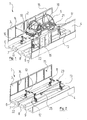
- FIG. 1 perspective view of a cabin is shown, which is generally designated by the reference numeral 1 and the Grobnahtabdichtung to vehicle bodies 2 is used.
- the cabin 1 has two parallel side walls 3, 4 and a ceiling, not shown, and also not shown opposite end walls in which the gates are located, via which the vehicle bodies 2 can be retracted into the interior of the cabin 1.
- the vehicle bodies 2 are held by a support frame 5, which is fed by a conveying system, not shown, for example, a monorail, the cabin 1, transported therethrough and optionally introduced into subsequent, similarly built cabins.
- the cabin 1 has a bottom 6 which, for reasons not of further interest here, has profiles 7, 8, 9 extending parallel to the conveying direction and extending like ribs.
- the vehicle body 2 is stopped in a position which is defined so precisely that the robots 10, 11, 12, 13 can spray all the seam areas of the vehicle body 2 intended for them.
- a stationary measuring system which in the present case comprises four cameras 14, 15, 16, 17 mounted on the side walls 3, 4 of the booth 1 (the two in FIG FIG. 1 front cameras 16, 17 are largely obscured by the side wall 4).
- the cameras 14, 15, 16, 17 determine the position of four fixedly connected to the vehicle body 2 reference points 18, 19, 20, 21, which may be, for example, four connected to the vehicle body 2 measuring balls.
- a vehicle body 2 immanenten coordinate system (here called "body coordinate system") in the cabin 1 are the axes of the robots 10, 11, 12, 13 are controlled taking into account this determined position so that the trajectory of the "Tool Center Point” (TCP) of the robot 10, 11, 12, 13 go through exactly the desired trajectory in the seam sealing process.
- TCP Tool Center Point
- This trajectory is defined by a plurality of interpolation points in a known manner, between which the control of the robots 10, 11, 12, 13 calculates an interpolation curve which the TCP of the robots 10, 11, 12, 13 follows between the individual interpolation points. From the deviations of the individual treatment positions of the various successive vehicle bodies necessarily follows that the interpolation points according to the measurements of the cameras 14, 15, 16, 17 must be recalculated for each vehicle body 2.
- a separate, cabin-fixed coordinate system "cabin coordinate system" called, furnished. This happens as in FIG. 2 represented in that in the interior of the cabin 1, in FIG. 2 on the profiles 7, 9, permanent reference points 22, 23, 24 (the reference point 24 is hidden by the profile 9) are attached. These reference points 22, 23, 24 may also be measuring balls. In the case of the car 1 as well, a fourth reference point could basically be used for checking purposes and for improving the measuring accuracy.
- the exact position of the reference points 22, 23, 24 is measured by means of a stationary measuring device 25.
- this is a laser tracker which is mounted on the top of the middle profile 8.
- the laser tracker 25 determines the vectors that lead from it to the individual reference points 22, 23, 24, from which, of course, if necessary, the position can be calculated in a Cartesian coordinate system.
- FIG. 3 A second preparation step is in FIG. 3 shown.
- This is the measurement of the various robots 10, 11, 12, 13.
- the position of an axis of all robots 10, 11, 12, 13 measured by the corresponding robot arm to the axis in question is rotated and the position of the TCP is measured in three different angular positions.
- the geometrical relationships within the robots 10, 11, 12, 13 are known, a relation between the cabin coordinate system and the internal robot coordinate system, that is, through the various axes of the robots 10, 11, 12, 13 defined coordinate system, manufactured.
- FIG. 3 For the sake of clarity, only the measurement of the robot 12 is shown; the others, in FIG. 3 Of course, not shown robots 10, 11, 13 are measured in the same way.
- FIG. 4 finally shows a third preparation step before the car 1 can go into operation.
- a measuring body 2 ' is shown, whose geometry and internal coordinate system coincide identically with geometry and internal coordinate system of the vehicle bodies 2 to be treated later. In principle, it would be sufficient for the step described here if a measurement object were used which has only the same reference points as the vehicle bodies 2.
- a measuring device 27 is attached, which is again preferably a laser tracker.
- a coordinate measuring machine is used as the external measuring system 28, this is because such a coordinate measuring machine 28 is anyway required to measure the measuring body 2 '.
- the coordinate measuring machine 28 is connected to a platform 29 on which three designed as measuring balls reference points 30, 31, 32 are attached. Again, the use of a fourth reference point at this point would be conceivable.
- the platform reference points 30, 31, 32 are read out by the laser tracker 27 connected to the measuring body 2 '.
- the coordinate measuring machine 28 in turn also measures the position of the platform reference points 30, 31, 32 and also the position of the body reference points 18 ', 19', 20 ', 21'.
- the measuring body 2 ' will now, as in FIG. 5 represented, moved by means of the conveyor system in an "ideal" machining position in the car 1.
- the reference points 18 ', 19', 20 ', 21' of the measuring body 2 ' are measured in their position.
- the laser tracker 27 connected to the measurement body 2 ' misses the car reference points 22, 23, 24, whereby a relationship between the body coordinate system and the car coordinate system in the "ideal" machining position can be established.
- the interpolation points to be approached by the various robots 10, 11, 12, 13 are now determined.
- Each vehicle body 2 is brought to an individual treatment position that is within the "reach" of the various robots 10, 11, 12, 13.
- this individual treatment position does not normally coincide exactly with the "ideal" machining position for which the measurement with the aid of the measuring body 2 'took place.
- the aid of the cameras 14, 15, 16, 17, which measure the reference points 18, 19, 20, 21 of the vehicle body 2 currently being processed it can be ascertained what kind the deviation between the individual occupied by the vehicle body 2 Treatment position and the "ideal" machining position is.
- laser trackers as measuring systems is particularly favorable in the present context, since three values are measured with each measurement and the measurement accuracy is in the range of a few hundredths of a millimeter.
- other measuring methods can also be used, in particular one-dimensional measuring systems. These are available in a variety of designs, such as cable, measuring boxes, laser triangulation, inexpensive. However, care must be taken with these systems to the accuracy of measurement, which should be at least in the range of a few tenths of a millimeter.
- FIG. 7 shows how such a linear measuring system, namely three distance sensors 40, 41, 42, which are mounted on the underside of the measuring body 2 ', is measured by means of a coordinate measuring machine 28. To mechanically align the distance sensors 40, 41, 42 requires two drives each.
Landscapes
- Engineering & Computer Science (AREA)
- Manufacturing & Machinery (AREA)
- Physics & Mathematics (AREA)
- General Physics & Mathematics (AREA)
- Automation & Control Theory (AREA)
- Human Computer Interaction (AREA)
- General Engineering & Computer Science (AREA)
- Quality & Reliability (AREA)
- Manipulator (AREA)
- Automobile Manufacture Line, Endless Track Vehicle, Trailer (AREA)
Claims (9)
- Procédé d'actionnement d'une cabine de traitement (1) équipée d'au moins un robot (10, 11, 12, 13), procédé dans lequela) les objets (2) à traiter sont pourvus d'au moins trois points de référence non situés sur une ligne droite, définissant ainsi un système de coordonnées desdits objets ;b) lesdits objets (2) à traiter sont amenés, dans la cabine de traitement (1), à un emplacement de traitement auquel ils se trouvent dans le rayon d'action du robot (10, 11, 12, 13) ;c) les coordonnées exactes des objets (2) sont déterminées audit emplacement de traitement par mesure des points de référence, sur lesdits objets (2), au moyen d'un dispositif mesureur fixe (14, 15, 16, 17) ;d) les axes du robot (10, 11, 12, 13) sont activés, par utilisation des coordonnées de l'objet (2) déterminées, de façon telle que le point central d'outil (TCP) dudit robot (10, 11, 12, 13) suive une trajectoire préétablie par plusieurs points d'appui ;
sachant que,e) préalablement au traitement des objets (2), il s'opère un processus de préparation et de mesure englobant les étapes suivantes :ea) un système de coordonnées de la cabine, faisant corps avec ladite cabine, est défini par instauration, dans l'espace intérieur de ladite cabine de traitement (1), d'au moins trois points de référence (22, 23, 24) qui ne sont pas situés sur une ligne droite, et dont les coordonnées sont mesurées par rapport à une quelconque origine faisant corps avec ladite cabine ;eb) le robot (10, 11, 12, 13) est mesuré dans ledit système de coordonnées de la cabine, permettant ainsi d'établir une relation mathématique entre le système de coordonnées du robot, préétabli par les axes dudit robot, et ledit système de coordonnées de la cabine ;f) l'actionnement de la cabine de traitement (1), proprement dit, inclut ensuite les étapes suivantes :fa) les objets (2) à traiter sont amenés à un emplacement individuel de traitement, dans ladite cabine de traitement (1) ;fb) un écart dudit emplacement individuel de traitement, par rapport à l'emplacement idéal de traitement, est déterminé à l'aide du dispositif mesureur fixe (14, 15, 16, 17) ;fc) les points d'appui, devant être abordés par le TCP du robot (10, 11, 12, 13), sont déplacés d'une manière correspondant audit écart mesuré de l'emplacement individuel de traitement, par rapport à l'emplacement idéal de traitement ;caractérisé par le fait que,g) préalablement au traitement des objets (2), il s'opère un processus supplémentaire de préparation et de mesure englobant les étapes suivantes :ga) un objet de mesure (2'), présentant les mêmes points de référence (18', 19', 20', 21') que les objets (2) à traiter, est relié à un dispositif mesureur mobile (27) qui est à même de mesurer les coordonnées de points de référence, dans son système de coordonnées de mesure ;gb) les points de référence (18', 19', 20', 21') dudit objet de mesure (2') sont mesurés avec implication dudit dispositif mesureur mobile (27), dans le système de coordonnées de mesure de ce dernier, de telle sorte qu'une relation mathématique puisse être établie entre le système de coordonnées de l'objet et le système de coordonnées de mesure ;gc) ledit objet de mesure (2') est amené dans la cabine de traitement (1), avec le système mesureur mobile (27), à un emplacement idéal de traitement auquel les points fixes de référence (22, 23, 24) de ladite cabine de traitement (1) sont mesurés à l'aide dudit système mesureur mobile (27), dans le système de coordonnées de mesure de ce dernier, de telle sorte qu'une relation mathématique puisse être établie entre le système de coordonnées de la cabine et le système de coordonnées de mesure, et donc également entre le système de coordonnées du robot et le système de coordonnées de l'objet. - Procédé selon la revendication 1, caractérisé par le fait qu'au moins une caméra (14, 15, 16, 17) est utilisée en tant que dispositif mesureur fixe.
- Procédé selon la revendication 1 ou 2, caractérisé par le fait qu'un laser de poursuite (25) est employé pour mesurer les points fixes de référence (22, 23, 24).
- Procédé selon l'une des revendications précédentes, caractérisé par le fait qu'un laser de poursuite (27) est employé en tant que système mesureur mobile.
- Procédé selon l'une des revendications précédentes, caractérisé par le fait qu'il est recouru à un système mesureur fixe extérieur (28) pour mesurer les coordonnées des points de référence (18', 19', 20', 21') de l'objet de mesure (2'), dans le système de coordonnées de mesure, sachant que ledit système mesureur fixe extérieur (28) mesure trois points fixes de référence (30, 31, 32) non reliés audit objet de mesure (2'), ainsi que lesdits points de référence (18', 19', 20', 21') dudit objet de mesure (2'), et que le système mesureur mobile (27) mesure lesdits points fixes de référence (30, 31, 32).
- Procédé selon la revendication 5, caractérisé par le fait que le système mesureur fixe extérieur est une machine (28) de mesure de coordonnées.
- Procédé selon l'une des revendications précédentes, caractérisé par le fait qu'il est prévu plusieurs cabines de traitement (1) parcourues, en succession, par l'objet de mesure (2') et par les objets (2) à traiter.
- Procédé selon l'une des revendications précédentes, caractérisé par le fait que les objets (2) à traiter sont des carrosseries de véhicules.
- Procédé selon l'une des revendications précédentes, caractérisé par le fait que le traitement se présente comme un revêtement, notamment comme un laquage.
Applications Claiming Priority (2)
| Application Number | Priority Date | Filing Date | Title |
|---|---|---|---|
| DE102010013391A DE102010013391A1 (de) | 2010-03-30 | 2010-03-30 | Verfahren zum Betreiben einer mit mindestens einem Roboter bestückten Behandlungskabine |
| PCT/EP2011/000810 WO2011120610A1 (fr) | 2010-03-30 | 2011-02-19 | Procédé permettant de faire fonctionner une cabine de traitement équipée d'au moins un robot |
Publications (2)
| Publication Number | Publication Date |
|---|---|
| EP2553536A1 EP2553536A1 (fr) | 2013-02-06 |
| EP2553536B1 true EP2553536B1 (fr) | 2014-05-14 |
Family
ID=44201789
Family Applications (1)
| Application Number | Title | Priority Date | Filing Date |
|---|---|---|---|
| EP11706174.7A Active EP2553536B1 (fr) | 2010-03-30 | 2011-02-19 | Procédé permettant de faire fonctionner une cabine de traitement équipée d'au moins un robot |
Country Status (3)
| Country | Link |
|---|---|
| EP (1) | EP2553536B1 (fr) |
| DE (1) | DE102010013391A1 (fr) |
| WO (1) | WO2011120610A1 (fr) |
Families Citing this family (3)
| Publication number | Priority date | Publication date | Assignee | Title |
|---|---|---|---|---|
| US10725478B2 (en) * | 2013-07-02 | 2020-07-28 | The Boeing Company | Robotic-mounted monument system for metrology systems |
| DE102014001376B3 (de) * | 2014-02-04 | 2015-01-08 | Daimler Ag | Abgleich von Koordinatensystemen mit Hilfe von Fahrzeuginnenraummerkmalen |
| DE102015006338A1 (de) * | 2015-05-19 | 2016-11-24 | Jan-Philipp Fuhr | Vorrichtung und Verfahren zur fotographischen Erfassung von Personenkraftwagen oder anderen gleichartigen Objekten |
Family Cites Families (7)
| Publication number | Priority date | Publication date | Assignee | Title |
|---|---|---|---|---|
| US6070109A (en) * | 1998-03-10 | 2000-05-30 | Fanuc Robotics North America, Inc. | Robot calibration system |
| EP1001251A1 (fr) * | 1998-11-10 | 2000-05-17 | Leica Geosystems AG | Système de positionnement par laser |
| US7289230B2 (en) * | 2002-02-06 | 2007-10-30 | Cyberoptics Semiconductors, Inc. | Wireless substrate-like sensor |
| ATE531488T1 (de) * | 2002-03-04 | 2011-11-15 | Vmt Vision Machine Technic Bildverarbeitungssysteme Gmbh | Verfahren zur bestimmung der lage eines objektes und eines werkstücks im raum zur automatischen montage des werkstücks am objekt |
| US6822412B1 (en) * | 2003-06-11 | 2004-11-23 | Zhongxue Gan | Method for calibrating and programming of a robot application |
| US8224607B2 (en) * | 2007-08-30 | 2012-07-17 | Applied Materials, Inc. | Method and apparatus for robot calibrations with a calibrating device |
| WO2009134708A1 (fr) * | 2008-04-28 | 2009-11-05 | University Of North Carolina At Charlotte | Procédés et systèmes de métrologie dynamique |
-
2010
- 2010-03-30 DE DE102010013391A patent/DE102010013391A1/de not_active Ceased
-
2011
- 2011-02-19 WO PCT/EP2011/000810 patent/WO2011120610A1/fr not_active Ceased
- 2011-02-19 EP EP11706174.7A patent/EP2553536B1/fr active Active
Also Published As
| Publication number | Publication date |
|---|---|
| WO2011120610A1 (fr) | 2011-10-06 |
| DE102010013391A1 (de) | 2011-10-06 |
| EP2553536A1 (fr) | 2013-02-06 |
Similar Documents
| Publication | Publication Date | Title |
|---|---|---|
| EP1602456B1 (fr) | Procédé et dispositif de commande de manipulateurs | |
| WO2019042504A1 (fr) | Chariot de transport et de positionnement d'un composant d'aéronef | |
| EP2663963B1 (fr) | Dispositif et procédé pour estimer la pose d'un objet dans une machine-outil | |
| EP3221094B1 (fr) | Procédé et système de correction d'une trajectoire d'usinage d'un outil guidé par un robot | |
| WO2008104167A2 (fr) | Procédé de vérification et d'étalonnage de machine basé sur une singularité | |
| EP2846943B1 (fr) | Procédé de manipulation automatisée d'un outil de cintrage et dispositif de fabrication | |
| EP0763406B1 (fr) | Méthode de détermination de la position d'un objet dans l'espace | |
| EP2297621B1 (fr) | Procédé et système pour l'application d'une matière de revêtement avec un robot programmable | |
| DE102015011535A1 (de) | Trajektorie-Anzeigevorrichtung zum Anzeigen von Motorende- und Maschinenende-Trajektorien | |
| DE19931676C2 (de) | Verfahren zum Vermessen von Werkstücken und Bearbeitungsstation | |
| DE69933947T2 (de) | Verfahren zur zellausrichtung und identifizierung und kalibrierung eines roboterwerkzeugs | |
| EP3037905A1 (fr) | Dispositif et procédé destinés à enregistrer des positions | |
| EP3441200A1 (fr) | Procédé et dispositif de référencement pour robots industriels | |
| WO2011120610A1 (fr) | Procédé permettant de faire fonctionner une cabine de traitement équipée d'au moins un robot | |
| DE202017102466U1 (de) | Vorrichtung zur Erkennung der genauen Position und Lage eines Bauteils in einer Bearbeitungsstation | |
| WO2017063636A1 (fr) | Dispositif et procédé d'usinage par laser d'une pièce réalisée sous forme de composant d'armoire de commande | |
| DE102012208252A1 (de) | Verfahren und Vorrichtung zur hochgenauen Positionierung eines durch einen Roboter geführten Werkzeugs | |
| DE102013007742B4 (de) | Verfahren und Vorrichtung zur Wiederherstellung der Betriebsbereitschaft einer mehrachsigen Bewegungseinrichtung | |
| DE102005051533B4 (de) | Verfahren zur Verbesserung der Positioniergenauigkeit eines Manipulators bezüglich eines Serienwerkstücks | |
| EP3045995A1 (fr) | Procede de traçage a partir de combinaison de pre-positionnement et mode manuel | |
| DE102006005990B4 (de) | Werkstückvermessung für 3-D Lageerkennung in mehreren Multi-Roboter-Stationen | |
| DE102013102651A1 (de) | System und Verfahren zur Absolutkalibrierung eines Manipulators | |
| DE102023128153B4 (de) | Robotergestützes Fertigungssystem | |
| DE102004033710B4 (de) | Verfahren zum Verbinden eines Hauptträgers mit mindestens einem Anbauteil durch Schweißen | |
| DE102021130535B3 (de) | System und Verfahren zur Positionierung einer bewegbaren Manipulatoreinheit |
Legal Events
| Date | Code | Title | Description |
|---|---|---|---|
| PUAI | Public reference made under article 153(3) epc to a published international application that has entered the european phase |
Free format text: ORIGINAL CODE: 0009012 |
|
| 17P | Request for examination filed |
Effective date: 20120913 |
|
| AK | Designated contracting states |
Kind code of ref document: A1 Designated state(s): AL AT BE BG CH CY CZ DE DK EE ES FI FR GB GR HR HU IE IS IT LI LT LU LV MC MK MT NL NO PL PT RO RS SE SI SK SM TR |
|
| DAX | Request for extension of the european patent (deleted) | ||
| GRAP | Despatch of communication of intention to grant a patent |
Free format text: ORIGINAL CODE: EPIDOSNIGR1 |
|
| INTG | Intention to grant announced |
Effective date: 20131018 |
|
| GRAS | Grant fee paid |
Free format text: ORIGINAL CODE: EPIDOSNIGR3 |
|
| GRAA | (expected) grant |
Free format text: ORIGINAL CODE: 0009210 |
|
| AK | Designated contracting states |
Kind code of ref document: B1 Designated state(s): AL AT BE BG CH CY CZ DE DK EE ES FI FR GB GR HR HU IE IS IT LI LT LU LV MC MK MT NL NO PL PT RO RS SE SI SK SM TR |
|
| REG | Reference to a national code |
Ref country code: GB Ref legal event code: FG4D Free format text: NOT ENGLISH |
|
| REG | Reference to a national code |
Ref country code: AT Ref legal event code: REF Ref document number: 668737 Country of ref document: AT Kind code of ref document: T Effective date: 20140615 |
|
| REG | Reference to a national code |
Ref country code: IE Ref legal event code: FG4D Free format text: LANGUAGE OF EP DOCUMENT: GERMAN |
|
| REG | Reference to a national code |
Ref country code: DE Ref legal event code: R096 Ref document number: 502011003087 Country of ref document: DE Effective date: 20140626 |
|
| REG | Reference to a national code |
Ref country code: NL Ref legal event code: VDEP Effective date: 20140514 |
|
| REG | Reference to a national code |
Ref country code: LT Ref legal event code: MG4D |
|
| PG25 | Lapsed in a contracting state [announced via postgrant information from national office to epo] |
Ref country code: FI Free format text: LAPSE BECAUSE OF FAILURE TO SUBMIT A TRANSLATION OF THE DESCRIPTION OR TO PAY THE FEE WITHIN THE PRESCRIBED TIME-LIMIT Effective date: 20140514 Ref country code: NO Free format text: LAPSE BECAUSE OF FAILURE TO SUBMIT A TRANSLATION OF THE DESCRIPTION OR TO PAY THE FEE WITHIN THE PRESCRIBED TIME-LIMIT Effective date: 20140814 Ref country code: CY Free format text: LAPSE BECAUSE OF FAILURE TO SUBMIT A TRANSLATION OF THE DESCRIPTION OR TO PAY THE FEE WITHIN THE PRESCRIBED TIME-LIMIT Effective date: 20140514 Ref country code: IS Free format text: LAPSE BECAUSE OF FAILURE TO SUBMIT A TRANSLATION OF THE DESCRIPTION OR TO PAY THE FEE WITHIN THE PRESCRIBED TIME-LIMIT Effective date: 20140914 Ref country code: GR Free format text: LAPSE BECAUSE OF FAILURE TO SUBMIT A TRANSLATION OF THE DESCRIPTION OR TO PAY THE FEE WITHIN THE PRESCRIBED TIME-LIMIT Effective date: 20140815 Ref country code: LT Free format text: LAPSE BECAUSE OF FAILURE TO SUBMIT A TRANSLATION OF THE DESCRIPTION OR TO PAY THE FEE WITHIN THE PRESCRIBED TIME-LIMIT Effective date: 20140514 |
|
| PG25 | Lapsed in a contracting state [announced via postgrant information from national office to epo] |
Ref country code: PL Free format text: LAPSE BECAUSE OF FAILURE TO SUBMIT A TRANSLATION OF THE DESCRIPTION OR TO PAY THE FEE WITHIN THE PRESCRIBED TIME-LIMIT Effective date: 20140514 Ref country code: ES Free format text: LAPSE BECAUSE OF FAILURE TO SUBMIT A TRANSLATION OF THE DESCRIPTION OR TO PAY THE FEE WITHIN THE PRESCRIBED TIME-LIMIT Effective date: 20140514 Ref country code: HR Free format text: LAPSE BECAUSE OF FAILURE TO SUBMIT A TRANSLATION OF THE DESCRIPTION OR TO PAY THE FEE WITHIN THE PRESCRIBED TIME-LIMIT Effective date: 20140514 Ref country code: RS Free format text: LAPSE BECAUSE OF FAILURE TO SUBMIT A TRANSLATION OF THE DESCRIPTION OR TO PAY THE FEE WITHIN THE PRESCRIBED TIME-LIMIT Effective date: 20140514 Ref country code: SE Free format text: LAPSE BECAUSE OF FAILURE TO SUBMIT A TRANSLATION OF THE DESCRIPTION OR TO PAY THE FEE WITHIN THE PRESCRIBED TIME-LIMIT Effective date: 20140514 Ref country code: LV Free format text: LAPSE BECAUSE OF FAILURE TO SUBMIT A TRANSLATION OF THE DESCRIPTION OR TO PAY THE FEE WITHIN THE PRESCRIBED TIME-LIMIT Effective date: 20140514 |
|
| PG25 | Lapsed in a contracting state [announced via postgrant information from national office to epo] |
Ref country code: PT Free format text: LAPSE BECAUSE OF FAILURE TO SUBMIT A TRANSLATION OF THE DESCRIPTION OR TO PAY THE FEE WITHIN THE PRESCRIBED TIME-LIMIT Effective date: 20140915 |
|
| PG25 | Lapsed in a contracting state [announced via postgrant information from national office to epo] |
Ref country code: DK Free format text: LAPSE BECAUSE OF FAILURE TO SUBMIT A TRANSLATION OF THE DESCRIPTION OR TO PAY THE FEE WITHIN THE PRESCRIBED TIME-LIMIT Effective date: 20140514 Ref country code: RO Free format text: LAPSE BECAUSE OF FAILURE TO SUBMIT A TRANSLATION OF THE DESCRIPTION OR TO PAY THE FEE WITHIN THE PRESCRIBED TIME-LIMIT Effective date: 20140514 Ref country code: CZ Free format text: LAPSE BECAUSE OF FAILURE TO SUBMIT A TRANSLATION OF THE DESCRIPTION OR TO PAY THE FEE WITHIN THE PRESCRIBED TIME-LIMIT Effective date: 20140514 Ref country code: SK Free format text: LAPSE BECAUSE OF FAILURE TO SUBMIT A TRANSLATION OF THE DESCRIPTION OR TO PAY THE FEE WITHIN THE PRESCRIBED TIME-LIMIT Effective date: 20140514 Ref country code: EE Free format text: LAPSE BECAUSE OF FAILURE TO SUBMIT A TRANSLATION OF THE DESCRIPTION OR TO PAY THE FEE WITHIN THE PRESCRIBED TIME-LIMIT Effective date: 20140514 |
|
| REG | Reference to a national code |
Ref country code: DE Ref legal event code: R097 Ref document number: 502011003087 Country of ref document: DE |
|
| PG25 | Lapsed in a contracting state [announced via postgrant information from national office to epo] |
Ref country code: NL Free format text: LAPSE BECAUSE OF FAILURE TO SUBMIT A TRANSLATION OF THE DESCRIPTION OR TO PAY THE FEE WITHIN THE PRESCRIBED TIME-LIMIT Effective date: 20140514 |
|
| PLBE | No opposition filed within time limit |
Free format text: ORIGINAL CODE: 0009261 |
|
| STAA | Information on the status of an ep patent application or granted ep patent |
Free format text: STATUS: NO OPPOSITION FILED WITHIN TIME LIMIT |
|
| 26N | No opposition filed |
Effective date: 20150217 |
|
| PG25 | Lapsed in a contracting state [announced via postgrant information from national office to epo] |
Ref country code: IT Free format text: LAPSE BECAUSE OF FAILURE TO SUBMIT A TRANSLATION OF THE DESCRIPTION OR TO PAY THE FEE WITHIN THE PRESCRIBED TIME-LIMIT Effective date: 20140514 |
|
| REG | Reference to a national code |
Ref country code: DE Ref legal event code: R097 Ref document number: 502011003087 Country of ref document: DE Effective date: 20150217 |
|
| PG25 | Lapsed in a contracting state [announced via postgrant information from national office to epo] |
Ref country code: BE Free format text: LAPSE BECAUSE OF NON-PAYMENT OF DUE FEES Effective date: 20150228 |
|
| PG25 | Lapsed in a contracting state [announced via postgrant information from national office to epo] |
Ref country code: SI Free format text: LAPSE BECAUSE OF FAILURE TO SUBMIT A TRANSLATION OF THE DESCRIPTION OR TO PAY THE FEE WITHIN THE PRESCRIBED TIME-LIMIT Effective date: 20140514 |
|
| PG25 | Lapsed in a contracting state [announced via postgrant information from national office to epo] |
Ref country code: LU Free format text: LAPSE BECAUSE OF FAILURE TO SUBMIT A TRANSLATION OF THE DESCRIPTION OR TO PAY THE FEE WITHIN THE PRESCRIBED TIME-LIMIT Effective date: 20150219 |
|
| REG | Reference to a national code |
Ref country code: CH Ref legal event code: PL |
|
| GBPC | Gb: european patent ceased through non-payment of renewal fee |
Effective date: 20150219 |
|
| PG25 | Lapsed in a contracting state [announced via postgrant information from national office to epo] |
Ref country code: MC Free format text: LAPSE BECAUSE OF FAILURE TO SUBMIT A TRANSLATION OF THE DESCRIPTION OR TO PAY THE FEE WITHIN THE PRESCRIBED TIME-LIMIT Effective date: 20140514 Ref country code: LI Free format text: LAPSE BECAUSE OF NON-PAYMENT OF DUE FEES Effective date: 20150228 Ref country code: CH Free format text: LAPSE BECAUSE OF NON-PAYMENT OF DUE FEES Effective date: 20150228 |
|
| REG | Reference to a national code |
Ref country code: DE Ref legal event code: R082 Ref document number: 502011003087 Country of ref document: DE Representative=s name: OSTERTAG & PARTNER, PATENTANWAELTE MBB, DE Ref country code: DE Ref legal event code: R081 Ref document number: 502011003087 Country of ref document: DE Owner name: EISENMANN SE, DE Free format text: FORMER OWNER: EISENMANN AG, 71032 BOEBLINGEN, DE |
|
| REG | Reference to a national code |
Ref country code: IE Ref legal event code: MM4A |
|
| REG | Reference to a national code |
Ref country code: FR Ref legal event code: ST Effective date: 20151030 |
|
| PG25 | Lapsed in a contracting state [announced via postgrant information from national office to epo] |
Ref country code: GB Free format text: LAPSE BECAUSE OF NON-PAYMENT OF DUE FEES Effective date: 20150219 Ref country code: IE Free format text: LAPSE BECAUSE OF NON-PAYMENT OF DUE FEES Effective date: 20150219 |
|
| PG25 | Lapsed in a contracting state [announced via postgrant information from national office to epo] |
Ref country code: FR Free format text: LAPSE BECAUSE OF NON-PAYMENT OF DUE FEES Effective date: 20150302 |
|
| PG25 | Lapsed in a contracting state [announced via postgrant information from national office to epo] |
Ref country code: MT Free format text: LAPSE BECAUSE OF FAILURE TO SUBMIT A TRANSLATION OF THE DESCRIPTION OR TO PAY THE FEE WITHIN THE PRESCRIBED TIME-LIMIT Effective date: 20140514 |
|
| REG | Reference to a national code |
Ref country code: AT Ref legal event code: MM01 Ref document number: 668737 Country of ref document: AT Kind code of ref document: T Effective date: 20160219 |
|
| PG25 | Lapsed in a contracting state [announced via postgrant information from national office to epo] |
Ref country code: HU Free format text: LAPSE BECAUSE OF FAILURE TO SUBMIT A TRANSLATION OF THE DESCRIPTION OR TO PAY THE FEE WITHIN THE PRESCRIBED TIME-LIMIT; INVALID AB INITIO Effective date: 20110219 Ref country code: SM Free format text: LAPSE BECAUSE OF FAILURE TO SUBMIT A TRANSLATION OF THE DESCRIPTION OR TO PAY THE FEE WITHIN THE PRESCRIBED TIME-LIMIT Effective date: 20140514 Ref country code: BG Free format text: LAPSE BECAUSE OF FAILURE TO SUBMIT A TRANSLATION OF THE DESCRIPTION OR TO PAY THE FEE WITHIN THE PRESCRIBED TIME-LIMIT Effective date: 20140514 Ref country code: AT Free format text: LAPSE BECAUSE OF NON-PAYMENT OF DUE FEES Effective date: 20160219 |
|
| PG25 | Lapsed in a contracting state [announced via postgrant information from national office to epo] |
Ref country code: TR Free format text: LAPSE BECAUSE OF FAILURE TO SUBMIT A TRANSLATION OF THE DESCRIPTION OR TO PAY THE FEE WITHIN THE PRESCRIBED TIME-LIMIT Effective date: 20140514 |
|
| PG25 | Lapsed in a contracting state [announced via postgrant information from national office to epo] |
Ref country code: MK Free format text: LAPSE BECAUSE OF FAILURE TO SUBMIT A TRANSLATION OF THE DESCRIPTION OR TO PAY THE FEE WITHIN THE PRESCRIBED TIME-LIMIT Effective date: 20140514 |
|
| PG25 | Lapsed in a contracting state [announced via postgrant information from national office to epo] |
Ref country code: AL Free format text: LAPSE BECAUSE OF FAILURE TO SUBMIT A TRANSLATION OF THE DESCRIPTION OR TO PAY THE FEE WITHIN THE PRESCRIBED TIME-LIMIT Effective date: 20140514 |
|
| REG | Reference to a national code |
Ref country code: DE Ref legal event code: R081 Ref document number: 502011003087 Country of ref document: DE Owner name: B+M SURFACE SYSTEMS GMBH, DE Free format text: FORMER OWNER: EISENMANN SE, 71032 BOEBLINGEN, DE |
|
| PGFP | Annual fee paid to national office [announced via postgrant information from national office to epo] |
Ref country code: DE Payment date: 20250219 Year of fee payment: 15 |