EP2553674B1 - Procédé d'éclairage d'un caisson lumineux - Google Patents
Procédé d'éclairage d'un caisson lumineux Download PDFInfo
- Publication number
- EP2553674B1 EP2553674B1 EP11723216.5A EP11723216A EP2553674B1 EP 2553674 B1 EP2553674 B1 EP 2553674B1 EP 11723216 A EP11723216 A EP 11723216A EP 2553674 B1 EP2553674 B1 EP 2553674B1
- Authority
- EP
- European Patent Office
- Prior art keywords
- light box
- light
- interface
- brightness
- control device
- Prior art date
- Legal status (The legal status is an assumption and is not a legal conclusion. Google has not performed a legal analysis and makes no representation as to the accuracy of the status listed.)
- Not-in-force
Links
Images
Classifications
-
- H—ELECTRICITY
- H05—ELECTRIC TECHNIQUES NOT OTHERWISE PROVIDED FOR
- H05B—ELECTRIC HEATING; ELECTRIC LIGHT SOURCES NOT OTHERWISE PROVIDED FOR; CIRCUIT ARRANGEMENTS FOR ELECTRIC LIGHT SOURCES, IN GENERAL
- H05B47/00—Circuit arrangements for operating light sources in general, i.e. where the type of light source is not relevant
- H05B47/10—Controlling the light source
- H05B47/105—Controlling the light source in response to determined parameters
- H05B47/11—Controlling the light source in response to determined parameters by determining the brightness or colour temperature of ambient light
-
- G—PHYSICS
- G09—EDUCATION; CRYPTOGRAPHY; DISPLAY; ADVERTISING; SEALS
- G09F—DISPLAYING; ADVERTISING; SIGNS; LABELS OR NAME-PLATES; SEALS
- G09F13/00—Illuminated signs; Luminous advertising
- G09F13/005—Illumination controller or illuminated signs including an illumination control system
-
- H—ELECTRICITY
- H05—ELECTRIC TECHNIQUES NOT OTHERWISE PROVIDED FOR
- H05B—ELECTRIC HEATING; ELECTRIC LIGHT SOURCES NOT OTHERWISE PROVIDED FOR; CIRCUIT ARRANGEMENTS FOR ELECTRIC LIGHT SOURCES, IN GENERAL
- H05B47/00—Circuit arrangements for operating light sources in general, i.e. where the type of light source is not relevant
- H05B47/10—Controlling the light source
- H05B47/105—Controlling the light source in response to determined parameters
- H05B47/115—Controlling the light source in response to determined parameters by determining the presence or movement of objects or living beings
-
- H—ELECTRICITY
- H05—ELECTRIC TECHNIQUES NOT OTHERWISE PROVIDED FOR
- H05B—ELECTRIC HEATING; ELECTRIC LIGHT SOURCES NOT OTHERWISE PROVIDED FOR; CIRCUIT ARRANGEMENTS FOR ELECTRIC LIGHT SOURCES, IN GENERAL
- H05B47/00—Circuit arrangements for operating light sources in general, i.e. where the type of light source is not relevant
- H05B47/10—Controlling the light source
- H05B47/175—Controlling the light source by remote control
-
- Y—GENERAL TAGGING OF NEW TECHNOLOGICAL DEVELOPMENTS; GENERAL TAGGING OF CROSS-SECTIONAL TECHNOLOGIES SPANNING OVER SEVERAL SECTIONS OF THE IPC; TECHNICAL SUBJECTS COVERED BY FORMER USPC CROSS-REFERENCE ART COLLECTIONS [XRACs] AND DIGESTS
- Y02—TECHNOLOGIES OR APPLICATIONS FOR MITIGATION OR ADAPTATION AGAINST CLIMATE CHANGE
- Y02B—CLIMATE CHANGE MITIGATION TECHNOLOGIES RELATED TO BUILDINGS, e.g. HOUSING, HOUSE APPLIANCES OR RELATED END-USER APPLICATIONS
- Y02B20/00—Energy efficient lighting technologies, e.g. halogen lamps or gas discharge lamps
- Y02B20/40—Control techniques providing energy savings, e.g. smart controller or presence detection
Definitions
- the invention relates to a method for illuminating a light box with at least two light sources and operating devices therefor.
- the present invention relates to a lighting system for illuminating a light box according to the preamble of claim 2.
- Light boxes are used today mainly for advertising lighting.
- classic incandescent lamps have been replaced by gas discharge lamps.
- the DE 4242204 A1 discloses a method and a device for illuminating light boxes with multicolored light sources, in particular colored fluorescent tubes, in color and intensity-changing operation.
- the colored light sources can be controlled by means of brightness control devices of a central control in their intensity, for example, according to program sequences in time sequences and varying intensity.
- the object of the invention is to improve the method for illuminating a light box with light source operating devices.
- a method for the control of electronically controlled light source operating devices is proposed.
- Typical examples of such a bulb operating device are electronic ballasts. (ECG) for gas discharge lamps or operating devices for organic or inorganic light emitting diodes.
- the invention also relates to a lighting system for controlling electronically controlled light source operating devices in light boxes, wherein the lighting system has a control unit, at least two light source operating devices and at least two sensors.
- the sensors are each connected to the controller, and the Leuchtstoffconcestechnik are also connected to the controller.
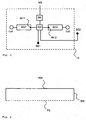
- Fig. 1 shows a schematic representation of a light box (10) with the included lighting.
- the light box (10) has an illumination system which serves to control at least two light sources (La1, La2).
- At least two operating devices (BG1, BG2) for operating in each case a lighting means (La1, La2) are present.
- the operating devices (BG1, BG2) each have a first interface (IN11, IN12) and the first interfaces (IN11, IN12) are interconnected.
- a control unit (SG) is also connected to the two operating devices (BG1, BG2) via the interface (IN11, IN12).
- At least two different sensors (SE1, SE2) are connected to the control unit (SG).
- the control unit (SG) transmits control signals via the first interface (IN11, IN12), which are dependent on the sensor signals detected by the sensors, and the light sources (La1, La2) are controlled by the operating devices (BG1, BG2) depending on the the first interface (IN11, IN12) control signals received.
- the operating devices (BG1, BG2) can optionally also transmit control signals via the first interface (IN11, IN12).
- the lighting means (La1, La2) can be controlled by the operating devices (BG1, BG2) as a function of the control signals received via the first interface (IN11, IN12).
- the bulbs (La1, La2) can be any desired bulbs, such as gas discharge lamps or organic or inorganic light emitting diodes.
- the illustrated operating devices (BG1, BG2) have connections that can be contacted with the protective conductor (earth), the phase conductor and the neutral conductor to supply power to the operating device (BG1, BG2).
- the operating device (BG1, Bug2) has a first interface (IN11, IN12) with the connections for connecting to a bus system (whereby this bus system does not necessarily have to be formed by a digital two-wire bus system, but, for example, also a system with an information transmission via the power line or via wireless communication).
- the first interface (IN11, IN12) can be designed so that digital commands can be communicated to the operating device via these connections, for example, in accordance with the DALI standard protocol or the DSI protocol from Tridonic, or the operating device can optionally also send signals.
- the first interface (IN11, IN12) may be configured so that signals can be transmitted by the supply voltage, such as the mains voltage or even push-button signals.
- first sensor (SE1) can monitor the brightness within the light box and by means of the second sensor (SE2) can monitor the brightness outside the light box.
- a motion detector can be connected to the control unit (SG). For example, it may respond to the approach or presence of a person and increase the brightness in the light box upon detection of an approach or presence of a person.
- the control unit (SG) can optionally perform an evaluation of the time of day based on the course of the ambient brightness and adjust the control of the operating devices (BG1, BG2) to the recorded time of day.
- the light box can have further operating devices with at least one first interface (IN11, IN12).
- the operating device (BG1, BG2) can additionally have a further (second) interface (IN21, IN22) (in Fig. 1 not shown).
- An additional sensor (SEB1, SEB2) for example a brightness sensor or a motion detector, can be connected to this further (second) interface (IN21, IN22).
- SEB1, SEB2 for example a brightness sensor or a motion detector.
- the respective use or usage of this further (second) interface (IN21, IN22) can be programmable.
- the sensor signals supplied via the further (second) interface can be signals from a motion detector or a brightness sensor.
- An operating device can, upon receipt of a signal transmitted via the first interface (IN11, IN12), evaluate the sensor signal from the further (second) interface (IN21, IN22). As already explained, an operating device (BG1, BG2) can correspondingly control the connected lighting device (La1, La2) upon receipt of a signal via the first interface (IN11, IN12) after evaluation of the control signal.
- the illumination system can also have further operating devices (BG3, BG4) with at least one first interface (IN13, IN14) (in Fig. 1 not shown).
- further operating devices (BG3) may be present, which also have a second interface (IN23), to which an optional additional sensor (SEB3) may be connected.
- bus coupler BK connected to the first interfaces (IN11, IN12) and allowing interface interfacing to a higher level control system (MS).
- control unit SG
- MS higher-level control system
- Bus coupling unit (BK) or the control unit (SG) to the higher-level control system (MS) is passed.
- the bus coupling unit (BK) can also be integrated in the control unit (SG).
- DALI commands can be transmitted as control signals that are passed on from the bus coupling unit (BK) to the higher-level control system.
- These control signals can be passed from the bus coupler (BK) directly as DALI commands to the higher-level control system, or be converted into another protocol and then passed to the higher-level control system (MS).
- deviating commands can be transmitted as control signals from the DALI standard (for example, according to a different protocol or in a protocol extended to the DALI standard), these control signals not being passed on from the bus coupling unit (BK) to the higher-level control system (MS).
- a local control within the lighting system with the operating devices can take place within the light box or within a room, this being done by means of monitoring by the various sensors (SE1, SE2, SE3), and
- external control information may be received from the supervisory control system (MS), such as power on and off commands, as well as information about the status of the lighting system (such as error messages or warnings) from the lighting system to the supervisory control system (MS).
- the bulbs can be an organic or inorganic LED or a gas discharge lamp (fluorescent lamp, high-pressure gas discharge lamp). But it may also be different bulbs, for example, it may be a lamp to an organic or inorganic LED and act in another to a gas discharge lamp (fluorescent lamp, high-pressure gas discharge lamp).
- the two bulbs are arranged within the light box.
- the light box can preferably be used for advertising lighting and it can take place by means of the first sensor (SE1) monitoring within the light box (10) and by means of the second sensor (SE2) monitoring outside the light box (10).
- efficient advertising lighting can be realized by means of a light box (10).
- Fig. 12 is a view of a typical construction of a light box (10) (shown is a section through the light box).
- This light box (10) may have a transparent or partially transparent front (FS).
- the light box (10) preferably has a reflective back (RW) or alternatively a transparent or partially transparent back (RW).
- the light box (10) may further comprise reflective side walls (SW) or transparent side walls (SW).
- the side walls (10) can also be designed as partially transparent side walls (10). Thus, when using reflective side panels (side walls or rear), reflector means for the light box (10) result.
- the light box (10) has at least two light sources (La1, La2), the light sources (La1, La2) preferably being aligned such that the light beams emitted by the light sources (La1, La2) and deflected by the reflector means between the back (RW) and the front (FS) of the light box (10) or on one of these two sides are irradiated.
- the front (FS) can be formed by a diffuser disk.
- the side walls (SW) as a partially transparent side parts, for example by a diffuser disc may be formed.
- the light box (10) can be regulated and optimally regulated as a function of the external brightness (detected by the sensor SE2) and also by the current brightness within the light box (detected by the sensor SE1) be set.
- a very energy-efficient illumination of a light box (10) can be achieved.
- the control unit (SG) can detect by monitoring the second sensor (SE2) when the ambient brightness (ie the external brightness) falls below a certain value. Now, the control unit (SG) according to the evaluation of the sensor signal of the second sensor (SE2) via the first interface (IN11, IN12) emit a corresponding control signal and by means of the operating devices (BG1, BG2) the control, preferably Adjust the brightness of the connected lamps (La1, La2).
- control unit (SG) can detect the current value of the brightness within the light box by means of the first sensor (SE1), which is also connected to the control unit (SG). Depending on the evaluation of the two sensors (SE1, SE2), the control unit (SG) can send out corresponding control signals via the first interface (IN11, IN12) and the operating units (BG1, BG2) can accordingly operate the connected light sources (La1, La2), for example, adjust their brightness.
- the other operating devices (BG3, BG4) connected to the first interface (IN13, IN14) via the bus system can also receive this control signal.
- all other operating devices (BG3, BG4) receive this control signal via their first interface (IN13, IN14).
- the first operating device (BG1) alternatively or additionally send out a control signal via the first interface (IN11) by evaluating the received control signals and the sensor signal detected via the second interface (IN21).
- This control signal can then be received by the second operating device (BG2) (via the first interface (IN12)) and this can adapt the activation of the light source (La2) in response to the received control signal.
- the illumination can thus be regulated and optimally adjusted for the illumination system within the light box (10).
- the dependence on the detected sensor signals can be interpreted in different directions and different operating modes for the individual lamps (La1, La2) can be defined.
- a motion detector for example a passive infrared sensor, also referred to as PIR
- a brightness sensor for example as a receiver for a remote control via infrared
- a color sensor for example as a second sensor (SE2) or further sensors (SE3)
- PIR passive infrared sensor
- SE2 infrared sensor
- SE3 color sensor
- SE3 further sensors
- a motion detector for example, to adjust the color temperature, the color locus or the emitted wavelength
- a combined sensor such as a brightness and motion sensor can be applied.
- a motion detector as a second sensor (SE2), for example, it is conceivable that upon perception of a movement in the vicinity of the light box (10) (ie outside), the lighting means (La1, La2) can be switched on or changed in their brightness accordingly.
- the monitoring within the light box can, for example, serve to compensate for brightness and / or color temperature (or also the color location or the emitted wavelength) as a result of aging of the lamps or also due to contamination, also a brightness fluctuation due to changes the temperature can thus be compensated (for example, a reduced efficiency of fluorescent lamps at low temperatures, for example in frost).
- the lighting system may also be designed such that a brightness sensor (for example a daylight sensor or a photodiode) is connected to the control unit (SG) as the first sensor (SE1).
- the brightness sensor can thus be arranged, for example, such that it detects the ambient light, ie the daylight. Depending on the detected ambient light, the brightness of the illumination system can be adjusted.
- a motion detector for example a passive infrared sensor, also referred to as PIR
- PIR passive infrared sensor
- the third sensor (SE3) for example, an infrared sensor (for example, as a receiver for a remote control by infrared, also called IR interface) to the control unit (SG) to be connected (not shown in FIG Fig. 1 ).
- This infrared sensor can be used for the programming and address assignment of the lighting system as well as for the specification of a desired brightness value.
- the brightness sensor as the first sensor (SE1) to detect the sum of artificial light generated by the lighting means (La1, La2) and the ambient light, so that the illumination system is correspondingly adjusted in its brightness .
- the brightness sensor can detect the sum of artificial light and the ambient light and adjust the brightness according to the specifications by adjusting the artificial light.
- control unit changes the brightness of the lamps (La1, La2) via corresponding control signals and detects the subsequent change in brightness by the brightness sensor.
- this changed control of the lighting means (La1, La2) can be maintained or a further change in the brightness of the lighting means (La1, La2) can be initiated by emitting new control signals.
- the proportion of artificial light and / or the proportion of ambient light can be determined. This can be done, for example, by a change in the proportion of artificial light, during which change the brightness change detected by the brightness sensor is evaluated, and based on this brightness change, it is possible to deduce the proportion of the artificial light and / or ambient light. In this case, the change in brightness can take place so rapidly that the change in brightness is imperceptible to the human eye.
- the artificial light can be deactivated at least for a short time (ie switched off) and for a measurement by means of a brightness sensor to take place in this switch-off phase.
- the artificial light can be turned on again and from the difference of the detected brightnesses can be concluded that the proportion of artificial light and ambient light.
- the switch-off phase can preferably be chosen to be so short that the change in brightness is imperceptible to the human eye.
- two separate brightness sensors could also be used, for example, one brightness sensor detecting the artificial light and another brightness sensor detecting the ambient light. It is thus also possible to connect additional sensors such as brightness sensors to the control unit (SG).
- BG1, BG2, BG3 may be present, all of which have a first interface (IN11, IN12, IN13), it may be advantageous, although several different individual sensors (SE1, SE2, SE3) to the control unit (SG), and thus can be easily built a very flexible and powerful lighting system for a light box.
- a method for illuminating a light box, preferably for advertising lighting, with at least two light sources, wherein two light sources (La1, La2) are each operated by one operating unit (BG1, BG2) and the operating units (BG1, BG2) are each one first interface (IN11, IN12) interconnected.
- a control unit (SG) is connected to the two operating devices (BG1, BG2) via the first interface (IN11, IN12), wherein at least two different sensors (SE1, SE2) are connected to the control unit (SG).
- the control unit (SG) transmits control signals via the first interface (IN11, IN12), which depend on the sensor signals detected by the sensors, and the light sources (La1, La2) are dependent on the first interface (IN11, IN12) triggered control signals.
Landscapes
- Physics & Mathematics (AREA)
- General Physics & Mathematics (AREA)
- Engineering & Computer Science (AREA)
- Theoretical Computer Science (AREA)
- Circuit Arrangement For Electric Light Sources In General (AREA)
- Illuminated Signs And Luminous Advertising (AREA)
Claims (13)
- Procédé d'éclairage d'un caisson lumineux (10), de préférence pour l'éclairage publicitaire, comprenant au moins deux moyens d'éclairage, dans lequel- deux moyens d'éclairage (La1, La2) sont respectivement commandés par un dispositif de fonctionnement (BG1, BG2),- les dispositifs de fonctionnement (BG1, BG2) sont respectivement reliés l'un à l'autre par une interface (IN11, IN12),- un dispositif de commande (SG) est relié aux deux dispositifs de fonctionnement (BG1, BG2) par l'interface (IN11, IN12),- au moins un capteur de luminosité est relié au dispositif de commande (SG),
caractérisé en ce que- le dispositif de commande (SG) envoie des signaux de commande via l'interface (IN11, IN12) qui dépendent des signaux du capteur obtenus par le capteur de luminosité, et les moyens d'éclairage (La1, La2) sont actionnés selon les signaux de commande obtenus via l'interface (IN11, IN12), dans lequel le capteur de luminosité acquiert la somme de la lumière artificielle, étant générée par les moyens d'éclairage (La1, La2), et de l'éclairage ambiant,- la lumière artificielle est désactivée au moins momentanément et mesurée au moyen du capteur (SE1) lors de cette phase d'extinction,- le pourcentage de lumière artificielle et d'éclairage ambiant est obtenu à partir de la différence des luminosités acquises,- le système d'éclairage est adapté dans sa luminosité selon les spécifications. - Caisson lumineux (10), de préférence pour l'éclairage publicitaire, doté d'au moins une face frontale transparente (FS), étant éclairée par au moins deux moyens d'éclairage, comprenant- au moins deux moyens d'éclairage (La1, La2),- au moins deux dispositifs de fonctionnement (BG1, BG2), destinés à commander, respectivement, un moyen d'éclairage (La1, La2), dans lequel les dispositifs de fonctionnement (BG1, BG2) possèdent respectivement une interface (IN11, IN12), lesdites interfaces (IN11, IN12) étant reliées l'une à l'autre et à un dispositif de commande (SG),
caractérisé en ce que- deux capteurs différents (SE1, SE2) sont reliés au dispositif de commande (SG) et les moyens d'éclairage (La1, La2) sont actionnés par les dispositifs de fonctionnement (BG1, BG2) selon les signaux de commande reçus via l'interface (IN11, IN12),- un des deux capteurs différents (SE1, SE2) est
configuré comme capteur de luminosité,
dans lequel le capteur de luminosité acquiert la somme de la lumière artificielle, étant générée par les moyens d'éclairage (La1, La2), et de l'éclairage ambiant,- en ce que le dispositif de commande est conçu de sorte que la lumière artificielle soit désactivée au moins momentanément et mesurée au moyen du capteur de luminosité lors de cette phase d'extinction, et- le pourcentage de lumière artificielle et d'éclairage ambiant est obtenu à partir de la différence des luminosités acquises,- le dispositif de commande (SG) adapte la luminosité des moyens d'éclairage (La1, La2) selon les spécifications. - Caisson lumineux (10) selon la revendication 2, caractérisé en ce que les capteurs (SE1, SE2) sont respectivement des capteurs de luminosité.
- Caisson lumineux (10) selon les revendications 2 ou 3, caractérisé en ce que une communication unidirectionnelle ou bidirectionnelle entre le dispositif de commande (SG) et les dispositifs de fonctionnement (BG1, BG2) est activée via l'interface (IN11, IN12).
- Caisson lumineux (10) selon l'une des revendications de 2 à 4, caractérisé en ce que un capteur infrarouge est raccordé au dispositif de commande (SG).
- Caisson lumineux (10) selon l'une des revendications de 2 à 5, comportant de plus des dispositifs de fonctionnement (BG3, BG4) ayant au moins une interface (IN13, IN14).
- Caisson lumineux (10) selon l'une des revendications de 2 à 6, caractérisé en la présence d'une travée de couplage (BK) reliée aux interfaces (IN11, IN12) et activant un couplage d'interface à un système de commande superordonné (MS).
- Caisson lumineux (10) selon l'une des revendications de 2 à 6, caractérisé en ce que le dispositif de commande (SG) active un couplage d'interface à un système de commande superordonné (MS).
- Caisson lumineux (10) selon les revendications 7 ou 8, caractérisé en ce que des signaux de commande différents peuvent être transmis via les interfaces (IN11, IN12), dans lequel uniquement une partie des signaux transmis est acheminée de la travée de couplage (BK) ou du dispositif de commande (SG) au système de commande superordonné (MS).
- Caisson lumineux (10) selon l'une des revendications de 2 à 9, caractérisé en ce que les moyens d'éclairage sont une DEL organique ou inorganique ou une lampe à décharge (lampe fluorescente, lampe à décharge haute pression).
- Caisson lumineux (10) selon l'une des revendications de 2 à 10, caractérisé en ce que le caisson lumineux (10) possède un côté postérieur réfléchissant (RW) ou un côté postérieur transparent (RW) .
- Caisson lumineux (10) selon l'une des revendications de 2 à 11, caractérisé en ce que le caisson lumineux (10) possède des cloisons latérales réfléchissantes (RW) ou des cloisons latérales transparentes (RW).
- Caisson lumineux (10) selon l'une des revendications de 2 à 12, caractérisé en ce que un détecteur de mouvement soit de plus relié au dispositif de commande (SG).
Applications Claiming Priority (2)
| Application Number | Priority Date | Filing Date | Title |
|---|---|---|---|
| AT2132010 | 2010-03-31 | ||
| PCT/AT2011/000156 WO2011120065A1 (fr) | 2010-03-31 | 2011-03-30 | Procédé d'éclairage d'un caisson lumineux |
Publications (2)
| Publication Number | Publication Date |
|---|---|
| EP2553674A1 EP2553674A1 (fr) | 2013-02-06 |
| EP2553674B1 true EP2553674B1 (fr) | 2016-06-08 |
Family
ID=44343892
Family Applications (1)
| Application Number | Title | Priority Date | Filing Date |
|---|---|---|---|
| EP11723216.5A Not-in-force EP2553674B1 (fr) | 2010-03-31 | 2011-03-30 | Procédé d'éclairage d'un caisson lumineux |
Country Status (6)
| Country | Link |
|---|---|
| US (2) | US20130074384A1 (fr) |
| EP (1) | EP2553674B1 (fr) |
| CN (1) | CN102934155B (fr) |
| DE (1) | DE112011101089A5 (fr) |
| RU (1) | RU2560311C2 (fr) |
| WO (1) | WO2011120065A1 (fr) |
Cited By (1)
| Publication number | Priority date | Publication date | Assignee | Title |
|---|---|---|---|---|
| DE102017130025B3 (de) | 2017-12-14 | 2019-03-07 | Klaus Wessling | Beleuchtungseinrichtung |
Families Citing this family (6)
| Publication number | Priority date | Publication date | Assignee | Title |
|---|---|---|---|---|
| US8872432B2 (en) * | 2012-03-15 | 2014-10-28 | General Electric Company | Solution for dynamic lighting control |
| DE102012205964C5 (de) * | 2012-04-12 | 2026-01-08 | Zumtobel Lighting Gmbh | Beleuchtungssystem und Verfahren hierfür |
| CN104582472B (zh) * | 2012-09-04 | 2018-06-05 | 飞利浦灯具控股公司 | 园艺照明系统以及使用这种园艺照明系统的园艺生产设施 |
| JP6429146B2 (ja) * | 2014-10-30 | 2018-11-28 | パナソニックIpマネジメント株式会社 | 照明制御方法およびそれを利用した照明制御システム、照明システム |
| WO2018198073A1 (fr) * | 2017-04-26 | 2018-11-01 | Gooee Limited | Carte de capteur pour luminaire/système d'éclairage |
| DE102018122985A1 (de) | 2018-09-19 | 2020-03-19 | Elkamet Kunststofftechnik Gmbh | Leuchtreklameanordnung und Leuchtreklame |
Family Cites Families (15)
| Publication number | Priority date | Publication date | Assignee | Title |
|---|---|---|---|---|
| US4236101A (en) * | 1978-08-18 | 1980-11-25 | Lutron Electronics Co., Inc. | Light control system |
| DE4242204A1 (de) * | 1992-12-15 | 1994-06-16 | Monika Kiesl | Verfahren und Vorrichtung zur Ausleuchtung von Leuchtkästen mit mehrfarbigen Lichtquellen in farb- und intensitätswechselnder Arbeitsweise |
| DE10143486A1 (de) * | 2001-09-05 | 2003-04-03 | Siemens Ag | Lichtmanagementsystem mit elektronischen Vorschaltgeräten EVG |
| CN101421558B (zh) * | 2003-03-24 | 2011-10-05 | 路创电子公司 | 控制空间中日光和人工照明和太阳眩光的系统 |
| CN1784933A (zh) * | 2003-05-02 | 2006-06-07 | 卢特龙电子公司 | 数字可寻址电子镇流器和控制单元 |
| DE10319693A1 (de) * | 2003-05-02 | 2004-11-25 | Klaus Burkard | Leuchte mit einem Leuchtenkörper |
| DE102004020216A1 (de) * | 2004-04-22 | 2005-11-10 | Manfred Kluth | Signalumsetzer |
| DE102004037653A1 (de) * | 2004-08-03 | 2006-02-23 | Siemens Ag | Verfahren zur Inbetriebnahme eines Beleuchtungssystems und Inbetriebnahmegerät |
| DE102004063594A1 (de) * | 2004-12-30 | 2006-07-13 | BSH Bosch und Siemens Hausgeräte GmbH | Verfahren zur Regelung der Hintergrundbeleuchtung eines Displays |
| US20080092075A1 (en) * | 2006-10-13 | 2008-04-17 | Joe Suresh Jacob | Method of building a database of a lighting control system |
| CN100578602C (zh) * | 2007-08-27 | 2010-01-06 | 重庆大学 | 户外全彩led大屏幕显示屏的自动亮度控制装置及方法 |
| RU72349U1 (ru) * | 2007-10-10 | 2008-04-10 | Общество с ограниченной ответственностью "АТОМИК" (ООО "АТОМИК") | Система для рекламирования |
| CN101621885A (zh) * | 2008-06-30 | 2010-01-06 | 深圳富泰宏精密工业有限公司 | 具亮度调节功能的照明装置及应用该照明装置的照明系统 |
| CA2957199C (fr) * | 2008-11-26 | 2019-01-08 | Wireless Environment, Llc | Dispositifs d'eclairage sans fil et applications associees |
| RU89746U1 (ru) * | 2009-10-05 | 2009-12-10 | Федеральное государственное унитарное предприятие "Производственное объединение "Уральский оптико-механический завод" имени Э.С. Яламова" (ФГУП "ПО "УОМЗ") | Информационное устройство |
-
2011
- 2011-03-30 US US13/637,395 patent/US20130074384A1/en not_active Abandoned
- 2011-03-30 DE DE112011101089T patent/DE112011101089A5/de not_active Withdrawn
- 2011-03-30 WO PCT/AT2011/000156 patent/WO2011120065A1/fr not_active Ceased
- 2011-03-30 RU RU2012143836/12A patent/RU2560311C2/ru not_active IP Right Cessation
- 2011-03-30 CN CN201180016609.2A patent/CN102934155B/zh not_active Expired - Fee Related
- 2011-03-30 EP EP11723216.5A patent/EP2553674B1/fr not_active Not-in-force
-
2017
- 2017-01-03 US US15/397,310 patent/US20170118820A1/en not_active Abandoned
Cited By (1)
| Publication number | Priority date | Publication date | Assignee | Title |
|---|---|---|---|---|
| DE102017130025B3 (de) | 2017-12-14 | 2019-03-07 | Klaus Wessling | Beleuchtungseinrichtung |
Also Published As
| Publication number | Publication date |
|---|---|
| EP2553674A1 (fr) | 2013-02-06 |
| DE112011101089A5 (de) | 2013-06-13 |
| RU2560311C2 (ru) | 2015-08-20 |
| CN102934155A (zh) | 2013-02-13 |
| CN102934155B (zh) | 2016-04-13 |
| US20170118820A1 (en) | 2017-04-27 |
| WO2011120065A1 (fr) | 2011-10-06 |
| RU2012143836A (ru) | 2014-05-10 |
| US20130074384A1 (en) | 2013-03-28 |
Similar Documents
| Publication | Publication Date | Title |
|---|---|---|
| DE102007045329B4 (de) | LED-Beleuchtungseinheit | |
| WO2011120065A1 (fr) | Procédé d'éclairage d'un caisson lumineux | |
| WO2008040454A2 (fr) | Module d'exploitation et procédé d'utilisation de moyens d'éclairage | |
| EP2364574A1 (fr) | Attribution d'adresse pour appareils de mise en fonctionnement de moyens d'éclairage compatibles bus en particulier pour led | |
| EP2305008A1 (fr) | Attribution d'une adresse de service à un appareil de service pour moyens d'éclairement à commande par bus | |
| DE102010020960A1 (de) | Leuchte und Leuchtensteuerungssystem | |
| EP2380404B1 (fr) | Procédé de commande d'appareils de service | |
| EP2218307A1 (fr) | Dispositif de fonctionnement pour moyens d'éclairage pour sortie de données | |
| DE102014202720A1 (de) | Beleuchtungssystem | |
| DE112011100662B4 (de) | Verfahren und Beleuchtungssystem zur Beleuchtung eines Lichtkastens | |
| EP2272305B1 (fr) | Système de commande de lumière et procédé de fonctionnement d'un système de commande de lumière | |
| WO2013023230A2 (fr) | Procédé d'addressage d'appareils d'actionnement d'éléments luminescents | |
| DE102013224760A1 (de) | Treiberschaltung und Verfahren zum Betrieb einer dimmbaren LED-Strecke in einem Dimmbereich mit zwei Bereichen | |
| WO2011123876A1 (fr) | Procédé pour l'éclairage d'un local | |
| DE112009002523B4 (de) | Verfahren zur Ansteuerung von Leuchtmittelbetriebsgeräten, Computersoftware-Programmprodukt, Leuchtmittelbetriebsgerät und System zur Ansteuerung von Leuchtmittelbetriebsgeräten | |
| EP2201824B1 (fr) | Interface pour appareil permettant de faire fonctionner un moyen d'éclairage | |
| WO2014176610A2 (fr) | Procédé de commande d'appareils de fonctionnement pour moyen d'éclairage | |
| DE112012004452B4 (de) | Beleuchtungssystem und Verfahren zur Beleuchtung eines Raumes | |
| DE102014101367A1 (de) | Anordnung und Verfahren zur Überwachung von LED-Beleuchtungssystemen sowie LED-Leuchte | |
| DE212015000089U1 (de) | Beleuchtungssystem und Steuergerät für ein Betriebsgerät für Leuchtmittel | |
| AT14574U1 (de) | Sensor zur Bewegungserfassung | |
| DE102007053793A1 (de) | Leuchtmittel-Betriebsgerät mit Schnittstelle | |
| EP3393208B1 (fr) | Système d'éclairage doté des générateurs de signaux | |
| WO2015143470A2 (fr) | Système d'éclairage équipé d'un contrôleur | |
| WO2011124400A2 (fr) | Capteur pour un équipement d'éclairage |
Legal Events
| Date | Code | Title | Description |
|---|---|---|---|
| PUAI | Public reference made under article 153(3) epc to a published international application that has entered the european phase |
Free format text: ORIGINAL CODE: 0009012 |
|
| 17P | Request for examination filed |
Effective date: 20121031 |
|
| AK | Designated contracting states |
Kind code of ref document: A1 Designated state(s): AL AT BE BG CH CY CZ DE DK EE ES FI FR GB GR HR HU IE IS IT LI LT LU LV MC MK MT NL NO PL PT RO RS SE SI SK SM TR |
|
| DAX | Request for extension of the european patent (deleted) | ||
| 17Q | First examination report despatched |
Effective date: 20140701 |
|
| GRAP | Despatch of communication of intention to grant a patent |
Free format text: ORIGINAL CODE: EPIDOSNIGR1 |
|
| INTG | Intention to grant announced |
Effective date: 20160120 |
|
| GRAS | Grant fee paid |
Free format text: ORIGINAL CODE: EPIDOSNIGR3 |
|
| GRAA | (expected) grant |
Free format text: ORIGINAL CODE: 0009210 |
|
| AK | Designated contracting states |
Kind code of ref document: B1 Designated state(s): AL AT BE BG CH CY CZ DE DK EE ES FI FR GB GR HR HU IE IS IT LI LT LU LV MC MK MT NL NO PL PT RO RS SE SI SK SM TR |
|
| REG | Reference to a national code |
Ref country code: GB Ref legal event code: FG4D Free format text: NOT ENGLISH |
|
| REG | Reference to a national code |
Ref country code: CH Ref legal event code: EP |
|
| REG | Reference to a national code |
Ref country code: IE Ref legal event code: FG4D Free format text: LANGUAGE OF EP DOCUMENT: GERMAN |
|
| REG | Reference to a national code |
Ref country code: AT Ref legal event code: REF Ref document number: 805722 Country of ref document: AT Kind code of ref document: T Effective date: 20160715 |
|
| REG | Reference to a national code |
Ref country code: DE Ref legal event code: R096 Ref document number: 502011009923 Country of ref document: DE |
|
| REG | Reference to a national code |
Ref country code: LT Ref legal event code: MG4D |
|
| REG | Reference to a national code |
Ref country code: NL Ref legal event code: MP Effective date: 20160608 |
|
| PG25 | Lapsed in a contracting state [announced via postgrant information from national office to epo] |
Ref country code: FI Free format text: LAPSE BECAUSE OF FAILURE TO SUBMIT A TRANSLATION OF THE DESCRIPTION OR TO PAY THE FEE WITHIN THE PRESCRIBED TIME-LIMIT Effective date: 20160608 Ref country code: NO Free format text: LAPSE BECAUSE OF FAILURE TO SUBMIT A TRANSLATION OF THE DESCRIPTION OR TO PAY THE FEE WITHIN THE PRESCRIBED TIME-LIMIT Effective date: 20160908 Ref country code: LT Free format text: LAPSE BECAUSE OF FAILURE TO SUBMIT A TRANSLATION OF THE DESCRIPTION OR TO PAY THE FEE WITHIN THE PRESCRIBED TIME-LIMIT Effective date: 20160608 |
|
| PG25 | Lapsed in a contracting state [announced via postgrant information from national office to epo] |
Ref country code: GR Free format text: LAPSE BECAUSE OF FAILURE TO SUBMIT A TRANSLATION OF THE DESCRIPTION OR TO PAY THE FEE WITHIN THE PRESCRIBED TIME-LIMIT Effective date: 20160909 Ref country code: HR Free format text: LAPSE BECAUSE OF FAILURE TO SUBMIT A TRANSLATION OF THE DESCRIPTION OR TO PAY THE FEE WITHIN THE PRESCRIBED TIME-LIMIT Effective date: 20160608 Ref country code: LV Free format text: LAPSE BECAUSE OF FAILURE TO SUBMIT A TRANSLATION OF THE DESCRIPTION OR TO PAY THE FEE WITHIN THE PRESCRIBED TIME-LIMIT Effective date: 20160608 Ref country code: RS Free format text: LAPSE BECAUSE OF FAILURE TO SUBMIT A TRANSLATION OF THE DESCRIPTION OR TO PAY THE FEE WITHIN THE PRESCRIBED TIME-LIMIT Effective date: 20160608 Ref country code: NL Free format text: LAPSE BECAUSE OF FAILURE TO SUBMIT A TRANSLATION OF THE DESCRIPTION OR TO PAY THE FEE WITHIN THE PRESCRIBED TIME-LIMIT Effective date: 20160608 Ref country code: ES Free format text: LAPSE BECAUSE OF FAILURE TO SUBMIT A TRANSLATION OF THE DESCRIPTION OR TO PAY THE FEE WITHIN THE PRESCRIBED TIME-LIMIT Effective date: 20160608 Ref country code: SE Free format text: LAPSE BECAUSE OF FAILURE TO SUBMIT A TRANSLATION OF THE DESCRIPTION OR TO PAY THE FEE WITHIN THE PRESCRIBED TIME-LIMIT Effective date: 20160608 |
|
| PG25 | Lapsed in a contracting state [announced via postgrant information from national office to epo] |
Ref country code: EE Free format text: LAPSE BECAUSE OF FAILURE TO SUBMIT A TRANSLATION OF THE DESCRIPTION OR TO PAY THE FEE WITHIN THE PRESCRIBED TIME-LIMIT Effective date: 20160608 Ref country code: SK Free format text: LAPSE BECAUSE OF FAILURE TO SUBMIT A TRANSLATION OF THE DESCRIPTION OR TO PAY THE FEE WITHIN THE PRESCRIBED TIME-LIMIT Effective date: 20160608 Ref country code: IS Free format text: LAPSE BECAUSE OF FAILURE TO SUBMIT A TRANSLATION OF THE DESCRIPTION OR TO PAY THE FEE WITHIN THE PRESCRIBED TIME-LIMIT Effective date: 20161008 Ref country code: IT Free format text: LAPSE BECAUSE OF FAILURE TO SUBMIT A TRANSLATION OF THE DESCRIPTION OR TO PAY THE FEE WITHIN THE PRESCRIBED TIME-LIMIT Effective date: 20160608 Ref country code: CZ Free format text: LAPSE BECAUSE OF FAILURE TO SUBMIT A TRANSLATION OF THE DESCRIPTION OR TO PAY THE FEE WITHIN THE PRESCRIBED TIME-LIMIT Effective date: 20160608 Ref country code: RO Free format text: LAPSE BECAUSE OF FAILURE TO SUBMIT A TRANSLATION OF THE DESCRIPTION OR TO PAY THE FEE WITHIN THE PRESCRIBED TIME-LIMIT Effective date: 20160608 |
|
| PG25 | Lapsed in a contracting state [announced via postgrant information from national office to epo] |
Ref country code: SM Free format text: LAPSE BECAUSE OF FAILURE TO SUBMIT A TRANSLATION OF THE DESCRIPTION OR TO PAY THE FEE WITHIN THE PRESCRIBED TIME-LIMIT Effective date: 20160608 Ref country code: PT Free format text: LAPSE BECAUSE OF FAILURE TO SUBMIT A TRANSLATION OF THE DESCRIPTION OR TO PAY THE FEE WITHIN THE PRESCRIBED TIME-LIMIT Effective date: 20161010 Ref country code: PL Free format text: LAPSE BECAUSE OF FAILURE TO SUBMIT A TRANSLATION OF THE DESCRIPTION OR TO PAY THE FEE WITHIN THE PRESCRIBED TIME-LIMIT Effective date: 20160608 |
|
| REG | Reference to a national code |
Ref country code: DE Ref legal event code: R097 Ref document number: 502011009923 Country of ref document: DE |
|
| REG | Reference to a national code |
Ref country code: FR Ref legal event code: PLFP Year of fee payment: 7 |
|
| PLBE | No opposition filed within time limit |
Free format text: ORIGINAL CODE: 0009261 |
|
| STAA | Information on the status of an ep patent application or granted ep patent |
Free format text: STATUS: NO OPPOSITION FILED WITHIN TIME LIMIT |
|
| 26N | No opposition filed |
Effective date: 20170309 |
|
| PG25 | Lapsed in a contracting state [announced via postgrant information from national office to epo] |
Ref country code: SI Free format text: LAPSE BECAUSE OF FAILURE TO SUBMIT A TRANSLATION OF THE DESCRIPTION OR TO PAY THE FEE WITHIN THE PRESCRIBED TIME-LIMIT Effective date: 20160608 Ref country code: DK Free format text: LAPSE BECAUSE OF FAILURE TO SUBMIT A TRANSLATION OF THE DESCRIPTION OR TO PAY THE FEE WITHIN THE PRESCRIBED TIME-LIMIT Effective date: 20160608 |
|
| REG | Reference to a national code |
Ref country code: CH Ref legal event code: PL |
|
| PG25 | Lapsed in a contracting state [announced via postgrant information from national office to epo] |
Ref country code: MC Free format text: LAPSE BECAUSE OF FAILURE TO SUBMIT A TRANSLATION OF THE DESCRIPTION OR TO PAY THE FEE WITHIN THE PRESCRIBED TIME-LIMIT Effective date: 20160608 |
|
| REG | Reference to a national code |
Ref country code: IE Ref legal event code: MM4A |
|
| PG25 | Lapsed in a contracting state [announced via postgrant information from national office to epo] |
Ref country code: LU Free format text: LAPSE BECAUSE OF NON-PAYMENT OF DUE FEES Effective date: 20170330 |
|
| PG25 | Lapsed in a contracting state [announced via postgrant information from national office to epo] |
Ref country code: CH Free format text: LAPSE BECAUSE OF NON-PAYMENT OF DUE FEES Effective date: 20170331 Ref country code: IE Free format text: LAPSE BECAUSE OF NON-PAYMENT OF DUE FEES Effective date: 20170330 Ref country code: LI Free format text: LAPSE BECAUSE OF NON-PAYMENT OF DUE FEES Effective date: 20170331 |
|
| REG | Reference to a national code |
Ref country code: BE Ref legal event code: MM Effective date: 20170331 |
|
| REG | Reference to a national code |
Ref country code: FR Ref legal event code: PLFP Year of fee payment: 8 |
|
| PG25 | Lapsed in a contracting state [announced via postgrant information from national office to epo] |
Ref country code: BE Free format text: LAPSE BECAUSE OF NON-PAYMENT OF DUE FEES Effective date: 20170331 |
|
| PGFP | Annual fee paid to national office [announced via postgrant information from national office to epo] |
Ref country code: AT Payment date: 20180328 Year of fee payment: 8 |
|
| PG25 | Lapsed in a contracting state [announced via postgrant information from national office to epo] |
Ref country code: MT Free format text: LAPSE BECAUSE OF FAILURE TO SUBMIT A TRANSLATION OF THE DESCRIPTION OR TO PAY THE FEE WITHIN THE PRESCRIBED TIME-LIMIT Effective date: 20160608 |
|
| PG25 | Lapsed in a contracting state [announced via postgrant information from national office to epo] |
Ref country code: AL Free format text: LAPSE BECAUSE OF FAILURE TO SUBMIT A TRANSLATION OF THE DESCRIPTION OR TO PAY THE FEE WITHIN THE PRESCRIBED TIME-LIMIT Effective date: 20160608 |
|
| REG | Reference to a national code |
Ref country code: DE Ref legal event code: R084 Ref document number: 502011009923 Country of ref document: DE |
|
| PG25 | Lapsed in a contracting state [announced via postgrant information from national office to epo] |
Ref country code: HU Free format text: LAPSE BECAUSE OF FAILURE TO SUBMIT A TRANSLATION OF THE DESCRIPTION OR TO PAY THE FEE WITHIN THE PRESCRIBED TIME-LIMIT; INVALID AB INITIO Effective date: 20110330 |
|
| PG25 | Lapsed in a contracting state [announced via postgrant information from national office to epo] |
Ref country code: BG Free format text: LAPSE BECAUSE OF FAILURE TO SUBMIT A TRANSLATION OF THE DESCRIPTION OR TO PAY THE FEE WITHIN THE PRESCRIBED TIME-LIMIT Effective date: 20160608 |
|
| PG25 | Lapsed in a contracting state [announced via postgrant information from national office to epo] |
Ref country code: CY Free format text: LAPSE BECAUSE OF NON-PAYMENT OF DUE FEES Effective date: 20160608 |
|
| REG | Reference to a national code |
Ref country code: AT Ref legal event code: MM01 Ref document number: 805722 Country of ref document: AT Kind code of ref document: T Effective date: 20190330 |
|
| PG25 | Lapsed in a contracting state [announced via postgrant information from national office to epo] |
Ref country code: MK Free format text: LAPSE BECAUSE OF FAILURE TO SUBMIT A TRANSLATION OF THE DESCRIPTION OR TO PAY THE FEE WITHIN THE PRESCRIBED TIME-LIMIT Effective date: 20160608 |
|
| PG25 | Lapsed in a contracting state [announced via postgrant information from national office to epo] |
Ref country code: AT Free format text: LAPSE BECAUSE OF NON-PAYMENT OF DUE FEES Effective date: 20190330 |
|
| PG25 | Lapsed in a contracting state [announced via postgrant information from national office to epo] |
Ref country code: TR Free format text: LAPSE BECAUSE OF FAILURE TO SUBMIT A TRANSLATION OF THE DESCRIPTION OR TO PAY THE FEE WITHIN THE PRESCRIBED TIME-LIMIT Effective date: 20160608 |
|
| PGFP | Annual fee paid to national office [announced via postgrant information from national office to epo] |
Ref country code: FR Payment date: 20200326 Year of fee payment: 10 |
|
| PG25 | Lapsed in a contracting state [announced via postgrant information from national office to epo] |
Ref country code: FR Free format text: LAPSE BECAUSE OF NON-PAYMENT OF DUE FEES Effective date: 20210331 |
|
| PGFP | Annual fee paid to national office [announced via postgrant information from national office to epo] |
Ref country code: GB Payment date: 20220322 Year of fee payment: 12 |
|
| P01 | Opt-out of the competence of the unified patent court (upc) registered |
Effective date: 20230530 |
|
| GBPC | Gb: european patent ceased through non-payment of renewal fee |
Effective date: 20230330 |
|
| PG25 | Lapsed in a contracting state [announced via postgrant information from national office to epo] |
Ref country code: GB Free format text: LAPSE BECAUSE OF NON-PAYMENT OF DUE FEES Effective date: 20230330 |
|
| PG25 | Lapsed in a contracting state [announced via postgrant information from national office to epo] |
Ref country code: GB Free format text: LAPSE BECAUSE OF NON-PAYMENT OF DUE FEES Effective date: 20230330 |
|
| PGFP | Annual fee paid to national office [announced via postgrant information from national office to epo] |
Ref country code: DE Payment date: 20240328 Year of fee payment: 14 |
|
| REG | Reference to a national code |
Ref country code: DE Ref legal event code: R119 Ref document number: 502011009923 Country of ref document: DE |
|
| PG25 | Lapsed in a contracting state [announced via postgrant information from national office to epo] |
Ref country code: DE Free format text: LAPSE BECAUSE OF NON-PAYMENT OF DUE FEES Effective date: 20251001 |