EP2553701B1 - Alarmhandschaltvorrichtung - Google Patents
Alarmhandschaltvorrichtung Download PDFInfo
- Publication number
- EP2553701B1 EP2553701B1 EP11712211.9A EP11712211A EP2553701B1 EP 2553701 B1 EP2553701 B1 EP 2553701B1 EP 11712211 A EP11712211 A EP 11712211A EP 2553701 B1 EP2553701 B1 EP 2553701B1
- Authority
- EP
- European Patent Office
- Prior art keywords
- operating element
- alarm device
- manual alarm
- base
- circuit board
- Prior art date
- Legal status (The legal status is an assumption and is not a legal conclusion. Google has not performed a legal analysis and makes no representation as to the accuracy of the status listed.)
- Active
Links
Images


Classifications
-
- H—ELECTRICITY
- H01—ELECTRIC ELEMENTS
- H01H—ELECTRIC SWITCHES; RELAYS; SELECTORS; EMERGENCY PROTECTIVE DEVICES
- H01H21/00—Switches operated by an operating part in the form of a pivotable member acted upon directly by a solid body, e.g. by a hand
- H01H21/02—Details
- H01H21/18—Movable parts; Contacts mounted thereon
- H01H21/22—Operating parts, e.g. handle
-
- H—ELECTRICITY
- H01—ELECTRIC ELEMENTS
- H01H—ELECTRIC SWITCHES; RELAYS; SELECTORS; EMERGENCY PROTECTIVE DEVICES
- H01H13/00—Switches having rectilinearly-movable operating part or parts adapted for pushing or pulling in one direction only, e.g. push-button switch
- H01H13/02—Details
- H01H13/12—Movable parts; Contacts mounted thereon
- H01H13/14—Operating parts, e.g. push-button
-
- H—ELECTRICITY
- H01—ELECTRIC ELEMENTS
- H01H—ELECTRIC SWITCHES; RELAYS; SELECTORS; EMERGENCY PROTECTIVE DEVICES
- H01H13/00—Switches having rectilinearly-movable operating part or parts adapted for pushing or pulling in one direction only, e.g. push-button switch
- H01H13/02—Details
- H01H13/12—Movable parts; Contacts mounted thereon
- H01H13/20—Driving mechanisms
-
- H—ELECTRICITY
- H01—ELECTRIC ELEMENTS
- H01H—ELECTRIC SWITCHES; RELAYS; SELECTORS; EMERGENCY PROTECTIVE DEVICES
- H01H9/00—Details of switching devices, not covered by groups H01H1/00 - H01H7/00
- H01H9/16—Indicators for switching condition, e.g. "on" or "off"
-
- H—ELECTRICITY
- H01—ELECTRIC ELEMENTS
- H01H—ELECTRIC SWITCHES; RELAYS; SELECTORS; EMERGENCY PROTECTIVE DEVICES
- H01H3/00—Mechanisms for operating contacts
- H01H3/02—Operating parts, i.e. for operating driving mechanism by a mechanical force external to the switch
- H01H3/022—Emergency operating parts, e.g. for stop-switch in dangerous conditions
- H01H2003/0233—Emergency operating parts, e.g. for stop-switch in dangerous conditions for alarm triggering, e.g. fire alarm, emergency off switches operated by breaking a glass
Definitions
- the present invention relates to an alarm device and, especially, to an alarm device with a switch or other devices which can be triggered by a manual touch in an abnormal condition.
- US 4,857,678 A discloses an electrical switch with contact carrier means for sliding in a first direction, a housing for slidably supporting the carrier means, terminal means mounted on the housing, a contact mounted on the carrier means for contacting the terminal means, and a plunger mounted on and slidable with the contact carrier for moving in a second direction substantially perpendicular to the first direction to cause said contact to engage or disengage the terminal means.
- EP 1 113 472 A1 discloses an electrical switch comprising two fixed contacts in a housing, a tripping member which can deform elastically in a direction perpendicular to the bottom of the housing, and an actuation pusher mounted so as to slide in a lateral direction parallel to the bottom of the housing, so as to convert the actuation force exerted on the pusher into a perpendicular tripping force.
- Modern manual alarm devices have to be usable in various harsh environments. For example, in the case of a high temperature, the plastic components of a manual fire alarm device when heated tends to creep, and the direction of the creeping deformation is usually parallel with the pressing direction of the manual alarm device, and then, even if there is no positive triggering on the alarm button, the alarm device may sound an alarm spontaneously, then the phenomenon of a false alarm occurs, which seriously affects the reliability of the manual alarm devices used at high temperatures.
- the object of the present invention is to provide a manual alarm device, which can work accurately and reliably regardless of the severe environments such as high temperature, sand storms, rains and snows, etc.
- the present invention intends to provide a manual alarm device, and for it to sound an alarm, the pressing direction by the operator is perpendicular to the triggering direction of the switch, thus avoiding a false alarm caused by the creeping deformation of the plastic components at a high temperature.
- the operating element can return to the plane which is in its state of monitoring after an operator has completed a pressing operation for sounding an alarm, so that even if in the state for sounding an alarm, the manual alarm device can also achieve good dust- and waterproof effects.
- the present invention provides a manual alarm device, and since the pressing direction is perpendicular to the direction of triggering the switch for sounding an alarm, the movement of the switch in the triggering direction when an operator presses the alarm device can be further used to produce a distinct visual change compared with the state of monitoring to prompt the user that the alarm device has been put in the state for sounding an alarm, which further improves its reliability and safety when being used.
- a manual alarm device comprising:
- the manual alarm device comprises a circuit board assembly with a switch unit thereon; an operating element which can be pressed along a pressing direction by an operator, including a contact member which can come into contact with the switch unit; and a base in which the circuit board assembly and the operating element can be disposed; the operating element further comprises a pair of lugs which are arranged on both sides of the end of the operating element away from the contact member; the base is further provided with a pair of guide rails, and the lugs are respectively disposed in each corresponding guide rail; and a locator is further disposed between the end of the operating element close to the lugs and the base corresponding thereto, so that when the operating element is pressed, the locator can drive the operating element to move in a direction perpendicular to the pressing direction, thus bringing the contact member on the operating element to separate from or to come into contact with said switch unit.
- the locator disposed between the end of the operating element close to the lugs and the base corresponding thereto is an elastic element with both ends respectively fixed on the lugs of the operating element and a protruded middle part bearing against a position of said base, which position is opposite to the end of said operating element close to the lugs.
- the locator can also be a spring, which spring is pressed between the end of the operating element close to the lugs and a position on said base, which position is opposite to the end of the operating element close to the lugs.
- the manual alarm device of the present invention further comprises an elastic member with one end being disposed on the base and the other end being pressed against the operating element, so as to enable the operating element, after the pressing on the operating element stops, to return to the same plane as it was when not being pressed.
- the elastic member can also be pushed against the operating element via an end cap.
- the operating element is further provided with a transparent hole, through which said circuit board assembly can be partly displayed.
- the circuit board assembly can be provided with a color sign on the position corresponding to the transparent hole of the operating element, and after the operating element is moved under the drive of the locator, the color sign can be shown through the transparent hole; alternatively, the circuit board assembly can be covered by a circuit board assembly cover, a color sign is disposed on the surface of the circuit board assembly cover towards the operating element, and after the operating element has moved under the drive of the locator, the color sign can be shown through the transparent hole.
- the manual alarm device further comprises an upper cover which is disposed together with the base, and a window is provided in the middle of the upper cover for the operating element to be pressed.
- the color sign on the circuit board assembly or the circuit board assembly cover can be shown by the window in the middle of the upper cover through the transparent hole on the operating element.
- the action direction of the operating element is parallel with the triggering direction of the switch unit, and the creeping direction of the operating element at a high temperature is often parallel with the action direction of the operating element too, therefore if the creeping direction is the same as the triggering direction of the switch unit, a false alarm may occur.
- the manual alarm devices provided in the present invention since the triggering direction of the switch unit is perpendicular to the creeping direction of the operating element, i.e. the creeping of the operating element cannot cause the switch element's position to change in the triggering direction, thus avoiding a false alarm.
- the operating element is in the same plane before and after sounding an alarm by means of the action of the elastic member, therefore it can effectively prevent water and dust from entering the manual alarm device.
- Fig. 1 is an exploded illustrative view of the structure of a manual alarm device of the present invention, which comprises a base 10, a circuit board assembly 20 and an operating element 40.
- the base 10 has two opposite side walls 11, and guide rails 12 (only one is shown in Fig. 1 ) corresponding to each other which are respectively disposed in the two opposite side walls 11.
- a circuit board assembly 20 is disposed in the base 10, and in the particular embodiment shown in Fig. 1 , two switch units 24 (only one switch unit 24 is illustratively shown in the figure) are disposed on the circuit board assembly 20; however, those skilled in the art would understand that the positions of the switch units can be disposed on the side of the circuit board assembly 20 facing the base 10, or on the other side facing away from the base 10, or on the two different sides of the circuit board assembly 20 respectively according to different situations.
- Fig. 1 indicates the case that two switch units 24 are used, those skilled in the art would understand that the number of switch units 24 can also be only one or more than two according to the particular structural design and the state of use.
- An operating element 40 is disposed on the circuit board assembly 20, and in the particular embodiment shown in Fig. 1 , two contact members 46 (only one contact member 46 is illustratively shown in the figure) are disposed on the operating element 40, and the contact members 46 can come into contact with or separate from the switch units 24 in the triggering direction shown in the figure.
- the contact members 46 are in contact with the switch units 24; and when the manual alarm device is in the state for sounding an alarm, the contact members 46 are separated from the switch units 24.
- a pair of lugs 44 (only one lug at one side is depicted in Fig.
- the lugs 44 are respectively disposed in the guide rails 12, and the lugs 44 can be moved in the guide rails 12 when the manual alarm device transforms from a state of monitoring to the state for sounding an alarm.
- a locator 50 is disposed between the end 48 of the operating element 40 and the side wall of the base 10 opposite to it.
- the locator 50 is made from an elastic material, and during the process, the manual alarm device transforms from the state of monitoring to the state for sounding an alarm, the elastic restoring force of the locator 50 can push the operating element 40 to move in the triggering direction as shown in the figure.
- the locator 50 is an elastic element, and it is conceivable by those skilled in the art that the locator 50 can use a spring compressed between the end 48 and the respective position in the base corresponding thereto.
- Fig. 2 is a cross-sectional view of the manual alarm device shown in Fig. 1 after it has been assembled, and in the state of monitoring as shown in Fig. 2 , the contact members 46 on the operating element 40 are in contact with the switch units 24 on the circuit board assembly 20, the locator 50 is connected between one end of the operating element 40 and one side wall of the base 10, a clip-hook 18 is disposed on the base 10, with the clip-hook 18 clipping the operating element 40 at the end close to the contact members 46, so as to prevent the operating element 40 from sliding at this moment under the effect of the elastic force of the locator 50 in the triggering direction shown in Fig. 2 .
- the lugs 44 of the operating element 40 are provided in the guide rails 12 of the base 10.
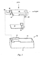
- Fig. 3 illustrates a perspective exploded view of another particular embodiment of the manual alarm device in the present invention, and the parts in this figure with the same or similar structures and the same functions as those in Fig. 1 will not be explained redundantly.
- the locator 50 is an elastic element with two ends each having a clamping part 52 (only one of them is shown in Fig. 3 ), the clamping parts 52 can be provided on the lugs 44 of the operating element 40, and the protruded middle part of the elastic element bears against the position on the base 10 opposing the end 48, thus realizing the pushing of the operating element 40 along the triggering direction.
- two elastic members 14 are disposed on the base 10 with one end of the elastic member 14 connected to the bottom face of the base 10 and the other end supporting the operating element 40, and when the operating element 40 is pressed, the elastic force of the elastic members 14 can make the operating element 40 return to the plane as it was previously.
- the elastic members 14 can not only support the operating element 40 directly, as shown in Fig. 3 , but also enter into end caps 16 first and then be connected with the operating element 40 via the end caps 16.
- the elastic members 14 can also be only one or more than two according to the particular structural design and the state of use. Likewise, the elastic members 14 can use not only the springs as shown in Fig. 3 , but also the elastic members with other structures but with the same function.
- circuit board assembly 20 is covered by a circuit board assembly cover 30.
- a transparent hole 42 is disposed in the middle of the operating element 40, and the circuit board assembly cover 30 can be observed through the transparent hole 42.
- the condition of the circuit board assembly 20 can be directly observed through the transparent hole 42.
- an apparent color sign 32 can be carried on the circuit board assembly cover 30, so that when the manual alarm device is in the state for sounding an alarm, the color sign 32 can be shown through the transparent hole 42 on the operating element 40, and when the manual alarm device is in the state of monitoring, the color sign 32 is not shown through the transparent hole 42.
- the color of the color sign 32 should be clearly distinguished from the circuit board assembly cover 30, so as to allow a user to distinguish the state of monitoring and the state for sounding an alarm of the manual alarm device from the colors.
- the color sign can also be disposed directly on the circuit board assembly 20, and a user can likewise observe the color change through the transparent hole 42.
- the manual alarm device can also include an upper cover 60, which upper cover 60 can be connected together with the base 10, and the circuit board assembly 20, the circuit board assembly cover 30 and the operating element 40, etc. of the manual alarm device are provided in the space defined by the upper cover 60 and the base 10.
- a window 62 is disposed in the middle of the upper cover 60 for the operating element to be pressed, and from the window 62 the alarming and state of monitoring shown by the transparent hole 42 on the operating element 40 can be observed. The user can look through the transparent hole 42 and the window 62, and when the color sign 32 is seen, it indicates that the manual alarm device is in the state for sounding an alarm.
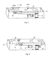
- Fig. 4 shows a schematic diagram of the manual alarm device in the state of monitoring, and at this moment, the contact members 46 on the operating element 40 are in contact with the switch units 24 on the circuit board assembly.
- an operator presses the operating element 40 along the pressing direction as shown in Fig. 4 , and at this moment, the operating element 40 pivots about the lugs 44 to the position shown in Fig. 5 .
- the operating element 40 is separated from the clip-hook 18 (referring to Fig. 2 ) on the base 10, the operating element 40 is free from the constraint of the clip-hook 18, the operating element 40 pivots about the lugs 44 towards the base 10, then the elastic members 14 on the base 10 are suppressed, and the operating element 40 slides under the effect of the elastic force of the locator 50 (referring to Fig. 2 ) along the triggering direction as shown in Fig. 5 .
- the contact members 46 on the operating element 40 start to separate from the switch units 24, and at the instant when the contact members 46 separate completely from the switch units 24, the manual alarm device produces an alarm signal.
- the lugs 44 of the operating element 40 move along the guide rails 12.
- the operating element 40 pivots under the elastic restoring force action of the elastic members 14 about the lugs 44 back towards the base 10 into the same plane as the operating element 40 stays in the state of monitoring (i.e., into the same plane as shown in Fig. 4 ), and the manual alarm device finishes the transition from the state of monitoring to the state for sounding alarm.
- the transparent hole 42 on the operating element 40 just moves to the top of the color sign 32 of the circuit board assembly cover 30, and at this moment, the user can observe the color sign 32 on the circuit board assembly cover 30 through the window 62 on the upper cover 60 and the transparent hole 42, thus confirming that the manual alarm device has been in the state for sounding an alarm.
- the switch units 24 are in contact with the contact members 46 in the state of monitoring; after the operating element 40 is pressed, referring to Fig. 6 , the switch units 24 separate from the contact members 46, and the manual alarm device sounds an alarm.
- the switch units are separated from the contact members in the state of monitoring, and after the operating element is pressed, the switch units are in contact with the contact members 46, and the manual alarm device sounds an alarm
- the operating element In an environment at a relatively high temperature, the operating element is likely to creep, and the creeping direction is usually parallel with the pressing direction of the operating element.
- the pressing direction of the operating element In the manual alarm device of the present invention, upon sounding an alarm, the pressing direction of the operating element is perpendicular to the triggering direction of the switch unit, therefore even if there is a creeping deformation in the pressing direction of the operating element, it will not cause the switch unit to be displaced in the triggering direction, thus effectively avoiding a false alarm of the manual alarm device from occurring at a high temperature.
- the operating element not only pivots about the lugs, but also produces a movement, and after the operating element finishes the alarming action, it can return to the same plane as it was when in the state of monitoring, which enables the manual alarm device of the present invention to have good dust- and waterproof characteristics.
- the color sign, the transparent hole and the window are respectively provided on the circuit board assembly cover, the operating element and the upper cover of the manual alarm device of the present invention, when the manual alarm device is in the state for sounding an alarm, the color sign, the transparent hole and the window can be superposed one on top of another, which is advantageous for users to determine what state the manual alarm device is in.
Landscapes
- Audible And Visible Signals (AREA)
- Fire Alarms (AREA)
- Alarm Systems (AREA)
- Emergency Alarm Devices (AREA)
Claims (12)
- Notrufschalter, aufweisend:eine Leiterplatten-Baugruppe (20) mit einer Schalteinheit (24) darauf;ein Bedienelement (40), welches entlang einer Drückrichtung gedrückt werden kann und ein Kontaktelement (46) umfasst, welches mit der Schalteinheit (24) in Kontakt kommen kann; undeine Basis (10), in welcher die Leiterplatten-Baugruppe (20) und das Bedienelement (40) angeordnet sein können;wobeidas Bedienelement (40) in der Basis (10) in der Richtung senkrecht zu der Drückrichtung bewegbar ist und drehgelenkig an der vom Ende des Kontaktelements (46) entfernten Seite angeordnet ist unddas Bedienelement (40) ferner mit einem Positionierelement (50) in der Nähe der und zwischen der vom Ende des Kontaktelements (46) entfernten Seite und der entsprechenden Basis dazu versehen ist, so dass, wenn eine Drückdistanz ein vorgegebenes Ausmaß übersteigt, das Positionierelement (50) das Bedienelement (40) dazu treiben kann, sich in eine Richtung senkrecht zu der Drückrichtung zu bewegen, wodurch es das Kontaktelement (46) auf dem Bedienelement (40) dazu bringt, sich von der Schalteinheit (24) zu trennen oder mit dieser in Kontakt zu kommen.
- Notrufschalter nach Anspruch 1, wobei das Bedienelement (40) ferner ein Paar Ansätze (44) aufweist, welche auf beiden Seiten des Endes des Bedienelements (40) angeordnet sind, das von dessen Kontaktelement (46) entfernt ist.
- Notrufschalter nach Anspruch 1, wobei die Basis (10) ferner mit einem Paar Führungsschienen (12) versehen ist und die Ansätze (44) jeweils bewegbar in einer entsprechenden Führungsschiene (12) angeordnet sind.
- Notrufschalter nach Anspruch 2, wobei das Positionierelement (50) ein elastisches Element ist, wobei zwei Enden desselben entsprechend an den Ansätzen (44) befestigt sind und ein vorstehendes Mittelteil desselben gegen eine Position auf der Basis (10) anliegt, wobei sich die Position gegenüber dem Ende des Bedienelements (40) in der Nähe von dessen Ansätzen (44) befindet.
- Notrufschalter nach Anspruch 2, wobei das Positionierelement (50) eine Feder ist, welche zwischen das Ende des Bedienelements (40) in der Nähe der Ansätze (44) und eine Position auf der Basis (10) gedrückt ist, wobei sich die Position gegenüber dem Ende des Bedienelements (40) in der Nähe von dessen Ansätzen (44) befindet.
- Notrufschalter nach Anspruch 1, welche ferner ein elastisches Element (14) aufweist, wobei ein Ende desselben auf der Basis (10) angeordnet ist und das andere Ende desselben gegen das Bedienelement (40) gedrückt ist, um zu ermöglichen, dass das Bedienelement (40), nachdem das Drücken auf das Bedienelement (40) beendet ist, in dieselbe Ebene zurückkehrt, in der es war, bevor es gedrückt wurde.
- Notrufschalter nach Anspruch 6, wobei das elastische Element (14) über eine Abschlusskappe gegen das Bedienelement (40) gedrückt ist.
- Notrufschalter nach Anspruch 1, wobei das Bedienelement (40) mit einer transparenten Öffnung (42) versehen ist, durch welche die Leiterplatten-Baugruppe (20) teilweise gezeigt werden kann.
- Notrufschalter nach Anspruch 8, wobei die Leiterplatten-Baugruppe (20) an der Position, welche der transparenten Öffnung (42) des Bedienelements (40) entspricht, mit einem Farbzeichen (32) versehen ist, und nachdem sich das Bedienelement (40) unter dem Antrieb des Positionierelements (50) bewegt hat, das Farbzeichen (32) durch die transparente Öffnung (42) gezeigt werden kann.
- Notrufschalter nach Anspruch 8, wobei die Leiterplatten-Baugruppe (20) von einer Leiterplatten-Baugruppen-Abdeckung (30) abgedeckt ist, ein Farbzeichen (32) auf der Oberfläche der Leiterplatten-Baugruppen-Abdeckung (30) dem Bedienelement (40) zugewandt angeordnet ist, und nachdem sich das Bedienelement (40) unter dem Antrieb des Positionierelements (50) bewegt hat, das Farbzeichen (32) durch die transparente Öffnung (42) gezeigt werden kann.
- Notrufschalter nach einem der Ansprüche 1 bis 8, wobei der Notrufschalter ferner eine obere Abdeckung (60) aufweist, die obere Abdeckung (60) zusammen mit der Basis (10) angeordnet ist und in der Mitte der oberen Abdeckung (60) ein Fenster (62) zum Drücken des Bedienelements (40) bereitgestellt ist.
- Notrufschalter nach Anspruch 9 oder 10, wobei der Notrufschalter ferner eine obere Abdeckung (60) aufweist, die obere Abdeckung (60) zusammen mit der Basis (10) angeordnet ist, in der Mitte der oberen Abdeckung (60) ein Fenster (62) zum Drücken des Bedienelements (40) bereitgestellt ist und, nachdem sich das Bedienelement (40) unter dem Antrieb des Positionierelements (50) bewegt hat, durch das Fenster (62) das Farbzeichen (32) gezeigt werden kann.
Applications Claiming Priority (2)
| Application Number | Priority Date | Filing Date | Title |
|---|---|---|---|
| CN 201010142076 CN102208126B (zh) | 2010-03-31 | 2010-03-31 | 手动报警装置 |
| PCT/EP2011/054405 WO2011120849A1 (en) | 2010-03-31 | 2011-03-23 | Manual alarm switching device |
Publications (2)
| Publication Number | Publication Date |
|---|---|
| EP2553701A1 EP2553701A1 (de) | 2013-02-06 |
| EP2553701B1 true EP2553701B1 (de) | 2014-04-30 |
Family
ID=44167696
Family Applications (1)
| Application Number | Title | Priority Date | Filing Date |
|---|---|---|---|
| EP11712211.9A Active EP2553701B1 (de) | 2010-03-31 | 2011-03-23 | Alarmhandschaltvorrichtung |
Country Status (3)
| Country | Link |
|---|---|
| EP (1) | EP2553701B1 (de) |
| CN (1) | CN102208126B (de) |
| WO (1) | WO2011120849A1 (de) |
Families Citing this family (4)
| Publication number | Priority date | Publication date | Assignee | Title |
|---|---|---|---|---|
| CN102750808B (zh) * | 2012-07-20 | 2014-04-02 | 无锡蓝天电子有限公司 | 手动火灾报警器的按钮结构 |
| CN103794009B (zh) * | 2014-03-06 | 2016-03-16 | 山东交通学院 | 便携式警示器 |
| CN104916064A (zh) * | 2015-06-19 | 2015-09-16 | 哈尔滨东方报警设备开发有限公司 | 一种火灾声光报警装置 |
| CN108766814B (zh) * | 2018-07-30 | 2024-04-16 | 深圳晶点光科有限公司 | 一种光纤手动消火栓按钮 |
Family Cites Families (7)
| Publication number | Priority date | Publication date | Assignee | Title |
|---|---|---|---|---|
| US4857678A (en) * | 1988-09-23 | 1989-08-15 | Emhart Industries, Inc. | Combination plunger and slider switch |
| FR2803428B1 (fr) * | 1999-12-30 | 2002-02-08 | Itt Mfg Entpr S Inc | Commutateur electrique a actionnement lateral |
| CN2562333Y (zh) * | 2002-08-19 | 2003-07-23 | 游聪谋 | 安全开关结构 |
| DE102004035193A1 (de) * | 2004-07-21 | 2006-02-16 | Schaltbau Gmbh | Mikroschalter |
| JP2007329022A (ja) * | 2006-06-08 | 2007-12-20 | Matsushita Electric Ind Co Ltd | プッシュスイッチ |
| DE102007020284A1 (de) * | 2007-04-30 | 2008-11-06 | Robert Bosch Gmbh | Meldevorrichtung mit manueller Auslösung und Alarmanzeige |
| FR2924858B1 (fr) * | 2007-12-06 | 2011-04-01 | Coactive Technologies Inc | Commutateur electrique a actionnement lateral et ensemble comportant un tel commutateur |
-
2010
- 2010-03-31 CN CN 201010142076 patent/CN102208126B/zh active Active
-
2011
- 2011-03-23 WO PCT/EP2011/054405 patent/WO2011120849A1/en not_active Ceased
- 2011-03-23 EP EP11712211.9A patent/EP2553701B1/de active Active
Also Published As
| Publication number | Publication date |
|---|---|
| CN102208126A (zh) | 2011-10-05 |
| EP2553701A1 (de) | 2013-02-06 |
| CN102208126B (zh) | 2013-06-12 |
| WO2011120849A1 (en) | 2011-10-06 |
| HK1158801A1 (en) | 2012-07-20 |
Similar Documents
| Publication | Publication Date | Title |
|---|---|---|
| US7916459B2 (en) | Key structure and electronic device having the key structure | |
| EP2068334B1 (de) | Elektrischer Schalter mit seitlicher Betätigung und Anordnung mit solchem Schalter | |
| CN110752117A (zh) | 接触器装置 | |
| EP2553701A1 (de) | Manuelle alarmumschaltungsvorrichtung | |
| CN109841438B (zh) | 一种微动开关的防尘结构 | |
| EP1801827B1 (de) | Vorrichtung mit einer Steueranordnung und einem Schaltgerät | |
| US4967043A (en) | Absorbing overtravel in sequential switching | |
| EP3151209B1 (de) | Brandmelder | |
| KR20070033262A (ko) | 작동영역이 넓은 절환장치 | |
| DE502004007576D1 (de) | Schutzschalter mit einer bimetallschnappscheibe | |
| WO2011120850A1 (en) | A reset mechanism for a manual alarm device and a manual alarm device with the same | |
| CN103632877B (zh) | 多方向开关装置 | |
| EP0510917A2 (de) | Umschaltungsvorrichtungen | |
| CN223092722U (zh) | 一种自动复位汽车按键开关 | |
| US3961146A (en) | Pretravel switch for portable tools | |
| CN216902648U (zh) | 一种辅助触头组件、操作机构及隔离开关 | |
| CN109192573B (zh) | 开关装置 | |
| HK1158801B (en) | A manual alarm device | |
| CN203103141U (zh) | 松绳检测开关 | |
| JPS608347Y2 (ja) | 押釦スイツチ装置 | |
| KR200224393Y1 (ko) | 화재발신기용 비상스위치의 누름장치 | |
| CN220963181U (zh) | 附件集成模块及断路器 | |
| JP4043313B2 (ja) | 押釦スイッチ | |
| US2942088A (en) | Electric switch | |
| EP4592983A1 (de) | Brandmelderrufpunkt auf der basis von leitfähiger farbe und verfahren dafür |
Legal Events
| Date | Code | Title | Description |
|---|---|---|---|
| PUAI | Public reference made under article 153(3) epc to a published international application that has entered the european phase |
Free format text: ORIGINAL CODE: 0009012 |
|
| 17P | Request for examination filed |
Effective date: 20120925 |
|
| AK | Designated contracting states |
Kind code of ref document: A1 Designated state(s): AL AT BE BG CH CY CZ DE DK EE ES FI FR GB GR HR HU IE IS IT LI LT LU LV MC MK MT NL NO PL PT RO RS SE SI SK SM TR |
|
| RAP1 | Party data changed (applicant data changed or rights of an application transferred) |
Owner name: SIEMENS AKTIENGESELLSCHAFT |
|
| DAX | Request for extension of the european patent (deleted) | ||
| REG | Reference to a national code |
Ref country code: DE Ref legal event code: R079 Ref document number: 602011006559 Country of ref document: DE Free format text: PREVIOUS MAIN CLASS: H01H0015100000 Ipc: H01H0019160000 |
|
| GRAP | Despatch of communication of intention to grant a patent |
Free format text: ORIGINAL CODE: EPIDOSNIGR1 |
|
| RIC1 | Information provided on ipc code assigned before grant |
Ipc: H01H 13/20 20060101ALI20131025BHEP Ipc: H01H 3/02 20060101ALI20131025BHEP Ipc: H01H 21/22 20060101ALI20131025BHEP Ipc: H01H 19/16 20060101AFI20131025BHEP Ipc: H01H 13/14 20060101ALI20131025BHEP Ipc: H01H 9/16 20060101ALI20131025BHEP |
|
| INTG | Intention to grant announced |
Effective date: 20131126 |
|
| GRAS | Grant fee paid |
Free format text: ORIGINAL CODE: EPIDOSNIGR3 |
|
| GRAA | (expected) grant |
Free format text: ORIGINAL CODE: 0009210 |
|
| AK | Designated contracting states |
Kind code of ref document: B1 Designated state(s): AL AT BE BG CH CY CZ DE DK EE ES FI FR GB GR HR HU IE IS IT LI LT LU LV MC MK MT NL NO PL PT RO RS SE SI SK SM TR |
|
| REG | Reference to a national code |
Ref country code: GB Ref legal event code: FG4D Ref country code: CH Ref legal event code: EP |
|
| REG | Reference to a national code |
Ref country code: AT Ref legal event code: REF Ref document number: 665603 Country of ref document: AT Kind code of ref document: T Effective date: 20140515 |
|
| REG | Reference to a national code |
Ref country code: IE Ref legal event code: FG4D |
|
| REG | Reference to a national code |
Ref country code: DE Ref legal event code: R096 Ref document number: 602011006559 Country of ref document: DE Effective date: 20140612 |
|
| REG | Reference to a national code |
Ref country code: AT Ref legal event code: MK05 Ref document number: 665603 Country of ref document: AT Kind code of ref document: T Effective date: 20140430 |
|
| REG | Reference to a national code |
Ref country code: LT Ref legal event code: MG4D |
|
| REG | Reference to a national code |
Ref country code: NL Ref legal event code: VDEP Effective date: 20140430 |
|
| PG25 | Lapsed in a contracting state [announced via postgrant information from national office to epo] |
Ref country code: GR Free format text: LAPSE BECAUSE OF FAILURE TO SUBMIT A TRANSLATION OF THE DESCRIPTION OR TO PAY THE FEE WITHIN THE PRESCRIBED TIME-LIMIT Effective date: 20140731 Ref country code: LT Free format text: LAPSE BECAUSE OF FAILURE TO SUBMIT A TRANSLATION OF THE DESCRIPTION OR TO PAY THE FEE WITHIN THE PRESCRIBED TIME-LIMIT Effective date: 20140430 Ref country code: IS Free format text: LAPSE BECAUSE OF FAILURE TO SUBMIT A TRANSLATION OF THE DESCRIPTION OR TO PAY THE FEE WITHIN THE PRESCRIBED TIME-LIMIT Effective date: 20140830 Ref country code: NL Free format text: LAPSE BECAUSE OF FAILURE TO SUBMIT A TRANSLATION OF THE DESCRIPTION OR TO PAY THE FEE WITHIN THE PRESCRIBED TIME-LIMIT Effective date: 20140430 Ref country code: NO Free format text: LAPSE BECAUSE OF FAILURE TO SUBMIT A TRANSLATION OF THE DESCRIPTION OR TO PAY THE FEE WITHIN THE PRESCRIBED TIME-LIMIT Effective date: 20140730 Ref country code: CY Free format text: LAPSE BECAUSE OF FAILURE TO SUBMIT A TRANSLATION OF THE DESCRIPTION OR TO PAY THE FEE WITHIN THE PRESCRIBED TIME-LIMIT Effective date: 20140430 Ref country code: FI Free format text: LAPSE BECAUSE OF FAILURE TO SUBMIT A TRANSLATION OF THE DESCRIPTION OR TO PAY THE FEE WITHIN THE PRESCRIBED TIME-LIMIT Effective date: 20140430 Ref country code: BG Free format text: LAPSE BECAUSE OF FAILURE TO SUBMIT A TRANSLATION OF THE DESCRIPTION OR TO PAY THE FEE WITHIN THE PRESCRIBED TIME-LIMIT Effective date: 20140730 |
|
| PG25 | Lapsed in a contracting state [announced via postgrant information from national office to epo] |
Ref country code: ES Free format text: LAPSE BECAUSE OF FAILURE TO SUBMIT A TRANSLATION OF THE DESCRIPTION OR TO PAY THE FEE WITHIN THE PRESCRIBED TIME-LIMIT Effective date: 20140430 Ref country code: PL Free format text: LAPSE BECAUSE OF FAILURE TO SUBMIT A TRANSLATION OF THE DESCRIPTION OR TO PAY THE FEE WITHIN THE PRESCRIBED TIME-LIMIT Effective date: 20140430 Ref country code: RS Free format text: LAPSE BECAUSE OF FAILURE TO SUBMIT A TRANSLATION OF THE DESCRIPTION OR TO PAY THE FEE WITHIN THE PRESCRIBED TIME-LIMIT Effective date: 20140430 Ref country code: LV Free format text: LAPSE BECAUSE OF FAILURE TO SUBMIT A TRANSLATION OF THE DESCRIPTION OR TO PAY THE FEE WITHIN THE PRESCRIBED TIME-LIMIT Effective date: 20140430 Ref country code: AT Free format text: LAPSE BECAUSE OF FAILURE TO SUBMIT A TRANSLATION OF THE DESCRIPTION OR TO PAY THE FEE WITHIN THE PRESCRIBED TIME-LIMIT Effective date: 20140430 Ref country code: SE Free format text: LAPSE BECAUSE OF FAILURE TO SUBMIT A TRANSLATION OF THE DESCRIPTION OR TO PAY THE FEE WITHIN THE PRESCRIBED TIME-LIMIT Effective date: 20140430 Ref country code: HR Free format text: LAPSE BECAUSE OF FAILURE TO SUBMIT A TRANSLATION OF THE DESCRIPTION OR TO PAY THE FEE WITHIN THE PRESCRIBED TIME-LIMIT Effective date: 20140430 |
|
| PG25 | Lapsed in a contracting state [announced via postgrant information from national office to epo] |
Ref country code: PT Free format text: LAPSE BECAUSE OF FAILURE TO SUBMIT A TRANSLATION OF THE DESCRIPTION OR TO PAY THE FEE WITHIN THE PRESCRIBED TIME-LIMIT Effective date: 20140901 |
|
| RAP2 | Party data changed (patent owner data changed or rights of a patent transferred) |
Owner name: SIEMENS SCHWEIZ AG |
|
| PG25 | Lapsed in a contracting state [announced via postgrant information from national office to epo] |
Ref country code: BE Free format text: LAPSE BECAUSE OF FAILURE TO SUBMIT A TRANSLATION OF THE DESCRIPTION OR TO PAY THE FEE WITHIN THE PRESCRIBED TIME-LIMIT Effective date: 20140430 Ref country code: RO Free format text: LAPSE BECAUSE OF FAILURE TO SUBMIT A TRANSLATION OF THE DESCRIPTION OR TO PAY THE FEE WITHIN THE PRESCRIBED TIME-LIMIT Effective date: 20140430 Ref country code: CZ Free format text: LAPSE BECAUSE OF FAILURE TO SUBMIT A TRANSLATION OF THE DESCRIPTION OR TO PAY THE FEE WITHIN THE PRESCRIBED TIME-LIMIT Effective date: 20140430 Ref country code: SK Free format text: LAPSE BECAUSE OF FAILURE TO SUBMIT A TRANSLATION OF THE DESCRIPTION OR TO PAY THE FEE WITHIN THE PRESCRIBED TIME-LIMIT Effective date: 20140430 Ref country code: DK Free format text: LAPSE BECAUSE OF FAILURE TO SUBMIT A TRANSLATION OF THE DESCRIPTION OR TO PAY THE FEE WITHIN THE PRESCRIBED TIME-LIMIT Effective date: 20140430 Ref country code: EE Free format text: LAPSE BECAUSE OF FAILURE TO SUBMIT A TRANSLATION OF THE DESCRIPTION OR TO PAY THE FEE WITHIN THE PRESCRIBED TIME-LIMIT Effective date: 20140430 |
|
| REG | Reference to a national code |
Ref country code: DE Ref legal event code: R097 Ref document number: 602011006559 Country of ref document: DE |
|
| PLBE | No opposition filed within time limit |
Free format text: ORIGINAL CODE: 0009261 |
|
| STAA | Information on the status of an ep patent application or granted ep patent |
Free format text: STATUS: NO OPPOSITION FILED WITHIN TIME LIMIT |
|
| PG25 | Lapsed in a contracting state [announced via postgrant information from national office to epo] |
Ref country code: IT Free format text: LAPSE BECAUSE OF FAILURE TO SUBMIT A TRANSLATION OF THE DESCRIPTION OR TO PAY THE FEE WITHIN THE PRESCRIBED TIME-LIMIT Effective date: 20140430 |
|
| 26N | No opposition filed |
Effective date: 20150202 |
|
| REG | Reference to a national code |
Ref country code: DE Ref legal event code: R081 Ref document number: 602011006559 Country of ref document: DE Owner name: SIEMENS SCHWEIZ AG, CH Free format text: FORMER OWNER: SIEMENS AKTIENGESELLSCHAFT, 80333 MUENCHEN, DE Effective date: 20150407 Ref country code: DE Ref legal event code: R097 Ref document number: 602011006559 Country of ref document: DE Effective date: 20150202 |
|
| PG25 | Lapsed in a contracting state [announced via postgrant information from national office to epo] |
Ref country code: SI Free format text: LAPSE BECAUSE OF FAILURE TO SUBMIT A TRANSLATION OF THE DESCRIPTION OR TO PAY THE FEE WITHIN THE PRESCRIBED TIME-LIMIT Effective date: 20140430 |
|
| PG25 | Lapsed in a contracting state [announced via postgrant information from national office to epo] |
Ref country code: MC Free format text: LAPSE BECAUSE OF FAILURE TO SUBMIT A TRANSLATION OF THE DESCRIPTION OR TO PAY THE FEE WITHIN THE PRESCRIBED TIME-LIMIT Effective date: 20140430 Ref country code: LU Free format text: LAPSE BECAUSE OF FAILURE TO SUBMIT A TRANSLATION OF THE DESCRIPTION OR TO PAY THE FEE WITHIN THE PRESCRIBED TIME-LIMIT Effective date: 20150323 |
|
| REG | Reference to a national code |
Ref country code: CH Ref legal event code: PL |
|
| GBPC | Gb: european patent ceased through non-payment of renewal fee |
Effective date: 20150323 |
|
| REG | Reference to a national code |
Ref country code: FR Ref legal event code: ST Effective date: 20151130 |
|
| REG | Reference to a national code |
Ref country code: IE Ref legal event code: MM4A |
|
| PG25 | Lapsed in a contracting state [announced via postgrant information from national office to epo] |
Ref country code: GB Free format text: LAPSE BECAUSE OF NON-PAYMENT OF DUE FEES Effective date: 20150323 Ref country code: CH Free format text: LAPSE BECAUSE OF NON-PAYMENT OF DUE FEES Effective date: 20150331 Ref country code: LI Free format text: LAPSE BECAUSE OF NON-PAYMENT OF DUE FEES Effective date: 20150331 Ref country code: IE Free format text: LAPSE BECAUSE OF NON-PAYMENT OF DUE FEES Effective date: 20150323 |
|
| PG25 | Lapsed in a contracting state [announced via postgrant information from national office to epo] |
Ref country code: FR Free format text: LAPSE BECAUSE OF NON-PAYMENT OF DUE FEES Effective date: 20150331 |
|
| PG25 | Lapsed in a contracting state [announced via postgrant information from national office to epo] |
Ref country code: MT Free format text: LAPSE BECAUSE OF FAILURE TO SUBMIT A TRANSLATION OF THE DESCRIPTION OR TO PAY THE FEE WITHIN THE PRESCRIBED TIME-LIMIT Effective date: 20140430 |
|
| PG25 | Lapsed in a contracting state [announced via postgrant information from national office to epo] |
Ref country code: SM Free format text: LAPSE BECAUSE OF FAILURE TO SUBMIT A TRANSLATION OF THE DESCRIPTION OR TO PAY THE FEE WITHIN THE PRESCRIBED TIME-LIMIT Effective date: 20140430 Ref country code: HU Free format text: LAPSE BECAUSE OF FAILURE TO SUBMIT A TRANSLATION OF THE DESCRIPTION OR TO PAY THE FEE WITHIN THE PRESCRIBED TIME-LIMIT; INVALID AB INITIO Effective date: 20110323 |
|
| PG25 | Lapsed in a contracting state [announced via postgrant information from national office to epo] |
Ref country code: TR Free format text: LAPSE BECAUSE OF FAILURE TO SUBMIT A TRANSLATION OF THE DESCRIPTION OR TO PAY THE FEE WITHIN THE PRESCRIBED TIME-LIMIT Effective date: 20140430 |
|
| PG25 | Lapsed in a contracting state [announced via postgrant information from national office to epo] |
Ref country code: MK Free format text: LAPSE BECAUSE OF FAILURE TO SUBMIT A TRANSLATION OF THE DESCRIPTION OR TO PAY THE FEE WITHIN THE PRESCRIBED TIME-LIMIT Effective date: 20140430 |
|
| PG25 | Lapsed in a contracting state [announced via postgrant information from national office to epo] |
Ref country code: AL Free format text: LAPSE BECAUSE OF FAILURE TO SUBMIT A TRANSLATION OF THE DESCRIPTION OR TO PAY THE FEE WITHIN THE PRESCRIBED TIME-LIMIT Effective date: 20140430 |
|
| P01 | Opt-out of the competence of the unified patent court (upc) registered |
Effective date: 20230523 |
|
| PGFP | Annual fee paid to national office [announced via postgrant information from national office to epo] |
Ref country code: DE Payment date: 20250520 Year of fee payment: 15 |