EP2553881B1 - Procédé de protection contre les superboucles dans un anneau ethernet - Google Patents
Procédé de protection contre les superboucles dans un anneau ethernet Download PDFInfo
- Publication number
- EP2553881B1 EP2553881B1 EP10849102.8A EP10849102A EP2553881B1 EP 2553881 B1 EP2553881 B1 EP 2553881B1 EP 10849102 A EP10849102 A EP 10849102A EP 2553881 B1 EP2553881 B1 EP 2553881B1
- Authority
- EP
- European Patent Office
- Prior art keywords
- ring
- ethernet ring
- ethernet
- node
- interface node
- Prior art date
- Legal status (The legal status is an assumption and is not a legal conclusion. Google has not performed a legal analysis and makes no representation as to the accuracy of the status listed.)
- Not-in-force
Links
- 238000000034 method Methods 0.000 title claims description 24
- 230000002457 bidirectional effect Effects 0.000 claims description 2
- 238000001514 detection method Methods 0.000 claims description 2
- 230000000903 blocking effect Effects 0.000 description 5
- 230000006399 behavior Effects 0.000 description 3
- 230000008901 benefit Effects 0.000 description 3
- 239000004305 biphenyl Substances 0.000 description 3
- 201000000760 cerebral cavernous malformation Diseases 0.000 description 3
- 230000007246 mechanism Effects 0.000 description 3
- 230000003213 activating effect Effects 0.000 description 2
- 238000010586 diagram Methods 0.000 description 2
- 230000006870 function Effects 0.000 description 2
- 101100433290 Homo sapiens ZNF471 gene Proteins 0.000 description 1
- 101100389697 Saccharomyces cerevisiae (strain ATCC 204508 / S288c) ERP1 gene Proteins 0.000 description 1
- 101100066419 Xenopus laevis fbxo43 gene Proteins 0.000 description 1
- 102100029037 Zinc finger protein 471 Human genes 0.000 description 1
- 230000002776 aggregation Effects 0.000 description 1
- 238000004220 aggregation Methods 0.000 description 1
- 230000005540 biological transmission Effects 0.000 description 1
- 238000004590 computer program Methods 0.000 description 1
- 230000008450 motivation Effects 0.000 description 1
- LWIHDJKSTIGBAC-UHFFFAOYSA-K potassium phosphate Substances [K+].[K+].[K+].[O-]P([O-])([O-])=O LWIHDJKSTIGBAC-UHFFFAOYSA-K 0.000 description 1
- 230000002265 prevention Effects 0.000 description 1
- 230000004044 response Effects 0.000 description 1
- 230000011664 signaling Effects 0.000 description 1
Images





Classifications
-
- H—ELECTRICITY
- H04—ELECTRIC COMMUNICATION TECHNIQUE
- H04L—TRANSMISSION OF DIGITAL INFORMATION, e.g. TELEGRAPHIC COMMUNICATION
- H04L12/00—Data switching networks
- H04L12/28—Data switching networks characterised by path configuration, e.g. LAN [Local Area Networks] or WAN [Wide Area Networks]
- H04L12/42—Loop networks
- H04L12/437—Ring fault isolation or reconfiguration
-
- H—ELECTRICITY
- H04—ELECTRIC COMMUNICATION TECHNIQUE
- H04L—TRANSMISSION OF DIGITAL INFORMATION, e.g. TELEGRAPHIC COMMUNICATION
- H04L12/00—Data switching networks
- H04L12/28—Data switching networks characterised by path configuration, e.g. LAN [Local Area Networks] or WAN [Wide Area Networks]
- H04L12/40—Bus networks
- H04L12/40143—Bus networks involving priority mechanisms
- H04L12/4015—Bus networks involving priority mechanisms by scheduling the transmission of messages at the communication node
-
- H—ELECTRICITY
- H04—ELECTRIC COMMUNICATION TECHNIQUE
- H04L—TRANSMISSION OF DIGITAL INFORMATION, e.g. TELEGRAPHIC COMMUNICATION
- H04L12/00—Data switching networks
- H04L12/28—Data switching networks characterised by path configuration, e.g. LAN [Local Area Networks] or WAN [Wide Area Networks]
- H04L12/46—Interconnection of networks
- H04L12/4637—Interconnected ring systems
Definitions
- the present invention relates to a method for use in an interface node and an interface node in a broadband communication network, and in particular to a method in an interface node in an Ethernet ring, and an interface node in an Ethernet ring for protecting against superloops going through the Ethernet ring.
- An Ethernet ring 15 is a collection of ring nodes forming a closed loop whereby each ring node is connected to two adjacent ring nodes via duplex communication links 16.
- Figure 1 illustrates an Ethernet ring 15 comprising 6 ring nodes connected to adjacent ring nodes via duplex communication links 16.
- a loop of data in the Ethernet ring 15 consumes a lot of resources in the Ethernet ring 15 and is therefore an undesired condition. There is therefore a need for protection against loops in the Ethernet ring 15.
- the topology of an Ethernet Ring Protection, ERP, network can be a single Ethernet ring or a collection of interconnected Ethernet rings.
- the G.8032 protocol is designed for Ethernet ring topologies and is developed as a standardized alternative to replace the spanning tree protocol, xSTP. It assumes standard 802.1 Q bridges are used and standard 802.3 MAC frames go around the Ethernet ring. G.8032 Ethernet ring nodes support standard FDB MAC learning, forwarding, flush behavior and port blocking/unblocking mechanisms.
- the principle of loop prevention within the Ethernet ring 15 is to block one of the ring links 16, either a pre-determined link or a failed link.
- one of the ring links 16 is designated as a Ring Protection Link, RPL, 90.
- the RPL 90 blocks Ethernet traffic to avoid traffic looping.
- An RPL blocking is provided by port blocking at both end of the RPL 90.
- One of the nodes is called RPL Owner Node, e.g. ring node E 95, which is also responsible for activating reversion behavior from protected or Manual Switching or Forced Switching conditions.
- the other node is called RPL Node, e.g. ring node D 97, which is not responsible for activating reversion behavior.
- G.8032 version 1 one end of RPL is blocked for breaking the loop in the normal state.
- both ends of RPL are blocked in a normal state to avoid unnecessary flooding.
- FIG. 2 illustrates an Ethernet Ring Protection, ERP, state.
- a link failure occurs, for example, a link 200 between Node A 210 and Node B 220.
- Node A 210 and Node B 220 block ports 211, 212 for the failed link 200 and send a R-APS, Ring-APS, Signal Failure messages to indicate the link failure.
- the Signal Failure messages are circulated around the Ethernet ring through a Ring APS channel (not shown).
- the RPL Owner Node E 230 and RPL Node D 240 receive this message, they unblock ports to RPL.
- Figure 3 illustrates an example of a multi-ring/ladder network 300 comprising two Ethernet rings 310, 320.
- the G.8032 standard also supports the multi-ring/ladder network 300 illustrated in figure 3 .
- RPL Owner Node and RPL node of each ring block the transmission and reception of traffic over the RPL for that ring.
- RPL Owner Node for ERP 1 is H 330 and for ERP 2 is E 340 .
- Figure 4 illustrates a multi-ring/ladder network 400 in which a superloop 410 can be created.
- a superloop 410 is formed when a shared link failure occurs. For example in Figure 4 , if a link 425 between Node A 420 and Node B 430 fails, as this link 425 belongs to both ring 1 440 and ring 2 450, both rings 440, 450 initiate protection and unblock ports to RPL. A superloop 410 is formed. We therefore need a special protection mechanism for multi-ring/ ladder network 400 to avoid the superloop problem.
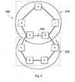
- FIG. 5 illustrates a Multi-ring/ladder network 500 with protection against a superloop.
- the superloop problem is solved by creating sub-rings.
- ERP 1 510 is composed of nodes A, B, I, H and G and all links therein between.
- ERP 2 520 is composed of nodes A, B, C, D , E and F and all links except a link 530 between A and B.
- the link 530 between A and B only belongs to ERP 1 510. If the link 530 between A and B fails, only ERP1 510 will respond and ERP 2 520 will do nothing.
- ERP 2 520 is a sub-ring as defined in G.8032, which transmits R-APS message on the R-APS virtual channel.
- a metro network is a network that covers a metropolitan area.
- the metro network is often based on the Ethernet standard.
- the metro network is commonly used as a metropolitan access network to connect subscribers and businesses to a larger service network or the Internet.
- G.8032 in an aggregation network and Virtual private LAN service, VPLS, in a core network.
- Figure 6 illustrates interworking between Provider edge, PE, routers 601, 602 and an Ethernet ring 603 running G.8032.
- the motivation of integrating Provider Edge routers 601, 602 into Ethernet ring 603 is to provide interface protection.
- an interface (not shown) facing the Ethernet ring may be G.8032 ring ports.
- the G.8032 ring control messages received on the ring ports of PE1 601 or PE2 602 are transmitted transparently through the tunnel back to the Ethernet ring 603. No local ring control messages are leaked to a core network 613. No link level CCMs are sent through the tunnel between PE1 and PE2.
- a link 604 between the Ring Bridge 605 and PE2 602 fails as shown figure 7 .
- PE2 602 does nothing.
- the adjacent ring bridge 605 initiates Ethernet ring protection after detecting the link failure by unblocking RPL 606.
- a tunnel 607 between PE1 601 and PE2 602 fails as in figure 8 .
- PE1 601 and PE2 602 know it is a tunnel failure when they do not receive IGP withdrawal of partner edge router PE1 601, PE 2 602 after certain amount of time. Any PE node 601, 602, 608, 609 will send a withdrawal message to other PE nodes 601, 602, 608, 609 if it finds out another PE node 601, 602, 608, 609 does not exist.
- PE1 601 and PE2 602 stop sending CCM from their ring interface towards ring bridges.
- the adjacent ring bridges 610, 611 detect there is a failure and initiate ring protection by unblocking RPL 612.
- the node of PE2 602 fails as in figure 9 .
- the adjacent ring bridge 611 initiates ring protection after detecting the failure, e.g. no CCMs.
- PE1 601 know it is a node failure when it receives IGP withdrawal message of PE2 602 from PE4 609.
- PE1 601 then also sends out SF, signal failure, message to adjacent ring bridge 610 to inform of this failure.
- the RPL 612 will be unblocked to provide protection.
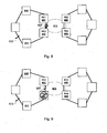
- Figure 10 illustrates a case where the core network 110 is segmented.
- the core network 110 is segmented into two portions 110a and 110b.
- a superloop 116 can be created if the existing mechanisms for protection against loops are used.
- the core network 110 is segmented into two parts 110a, 110b and there is therefore no communication between PE 1 601, PE2 602 and PE3 608, PE4 609, respectively.
- PE1 601 Since the core network is segmented into two parts 110a, 110b, PE1 601 is only connected to PE3 608 and PE2 602 is only connected to PE4 609. There is no communication between PE1 601, PE3 608 and PE2 602, PE4 609. PE1 601 will send out withdrawal messages about PE2 602 and PE4 609. PE2 602 will send out withdrawal messages about PE1 601 and PE3 608. PE3 608 will send out withdrawal messages about PE2 602 and PE4 609. PE4 609 will send out withdrawal messages about PE1 601 and PE3 608. After receiving those withdrawal messages, PE1 601 will assume PE2 602 has a node failure, at the same time, PE2 602 will assume PE1 601 has a node failure.
- Both PE1 601 and PE2 602 will send out SF message to adjacent ring bridges 125 to initiate the ring protection by unblocking RPL 160.
- PE3 608 and PE4 609 will behave the same way to unblock RPL 127 to provide protection. The result will be a superloop 116 as shown in Figure 10 .
- An object of the present invention is thus to provide a method and an arrangement for increasing the robustness of Ethernet rings by preventing a superloop from being created.
- the present invention relates to a method in an interface node for protecting an Ethernet ring from a superloop going through the Ethernet ring.
- the Ethernet ring comprises a pair of interface nodes between the Ethernet ring and a VPLS-domain.
- the method comprising the steps of: receiving in the interface nodes a priority message indicating a priority level for each Ethernet ring connected to the VPLS-domain; receiving in the interface nodes a withdrawal message intended to indicate that the other interface node is malfunctioning; and transmitting from the interface node a signal failure message to the Ethernet ring in a case any of the other Ethernet rings has a lower priority level than the Ethernet ring.
- the object is achieved according to the present invention by implementing a coordinating protocol among the Ethernet rings connected to the VPLS-domain.
- a priority message is received in the interface node indicating a priority level for each Ethernet ring connected to the VPLS-domain.
- an interface node in an Ethernet ring receives a message indicating that the other interface node in the Ethernet ring is malfunctioning it only transmit a signal failure message in a case any other Ethernet ring has a lower priority than the Ethernet ring to which the interface node belongs.
- the present invention relates to an interface node for protecting an Ethernet ring from a superloop going through the Ethernet ring, wherein the Ethernet ring comprises a pair of interface nodes between the Ethernet ring and a VPLS-domain, the interface node comprising: receiving means for receiving a priority message indicating a priority level for each Ethernet ring connected to the VPLS-domain.
- the receiving means being further configured for receiving a withdrawal message intended to indicate that the other interface node is malfunctioning; and transmitting means configured to transmitting a signal failure message to the Ethernet ring in a case any of the other Ethernet rings has a lower priority level than the Ethernet ring.
- An advantage with embodiments of the present invention is that a superloop can not be created since at least one Ethernet ring will keep its ring protection link in response to a message indicating that its partner interface node is malfunctioning.
- Yet another advantage with embodiments of the present invention is that less network resources are consumed since a superloop is prevented from being created. Yet another advantage of embodiments of the present invention is that a failure rate of the network also is reduced, since no superloop can be created.
- the network 100 comprises a core network 110 and at least one Ethernet ring 120, 130.
- the Ethernet ring 120 comprises at least one ring node 125 and two interface nodes PE1 140, PE2 150 between the Ethernet ring 120 and the core network 110.
- the Ethernet ring 130 also comprises at least one ring node 136 and two interface nodes PE 3 141, PE 4 151 between the Ethernet ring 130 and the core network 110.
- the core network 110 may be a VPLS-domain.
- the Ethernet ring 120 comprises a ring protection link 160 for protecting the Ethernet ring 120 from loops.
- the Ethernet ring 130 also comprises a ring protection link 175 for protecting the Ethernet ring 130 from loops.
- a ring protection link 175 for protecting the Ethernet ring 130 from loops.
- priority messages (not shown) exchanged between the PE nodes 140, 150, 141 and 151. These priority messages indicate a priority level for each of the Ethernet rings 120, 130 connected to the VPLS-domain 110.
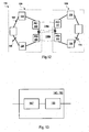
- FIG 12 illustrates a certain situations where the core network 110 is segmented.
- the core network 110 can for instance be segmented into two parts 110 a and 110 b as illustrated in figure 12 .
- the core network 110 is segmented into two parts 110 a and 110 b as illustrated in figure 12 .
- PE 4 151 Since the core network is segmented PE 4 151 does not have any communication path to PE1 140. PE 4 151 will therefore send out a withdrawal message (not shown) indicating that PE 4 151 can not reach PE 1 140. This withdrawal message will be received by PE2 150.
- PE2 150 will then assume that PE 1 140 has a node failure.
- PE2 150, PE3 141 and PE4 151 they will all assume their respective partner PE-node has a node failure. This since they will receive a withdrawal message concerning their respective partner PE node.
- each PE-node 140, 150, 141 and 151 have, respectively, received a priority message indicating a priority level for each Ethernet ring 120, 130 connected to the VPLS-domain 110.
- the PE-nodes 140, 150 will, according to the present invention, transmit a signal failure message to the Ethernet ring 120 since there is another Ethernet ring 130 with a lower priority level, as indicated by the priority messages received by the PE-nodes 140, 150. This will result in that the ring protection link 160 will be unblocked.
- PE3 141 and PE4 151 will, according to the present invention, on the other hand not transmit any signal failure messages to the Ethernet ring 130 since there is no other Ethernet ring with a lower priority level, as indicated by the priority messages received by the PE-nodes 141, 151. This will result in that the ring protection link 175 will stayed blocked. Since the ring protection link 175 will stayed blocked a superloop (not shown) can not be created in a network 113.
- a signal failure message is according to exemplary embodiments of the present invention transmitted, from the PE-nodes 140, 150, 141, 151 to its respective Ethernet ring 120, 130 in a case the respective PE-node have information that there exists any other Ethernet ring 120, 130 with a lower priority level.
- In another exemplary embodiment of the present invention is a signal failure message transmitted from the respective PE-node 140, 150, 141, 151 to its respective Ethernet ring 120, 130 in case the respective PE-node 140, 150, 141, 151 belongs to an Ethernet ring which is the only Ethernet ring connected to the VPLS-domain 110.
- the priority messages may in an exemplary embodiment of the present invention be periodically transmitted in the VPLS-domain 110.
- the periodically sent messages may according to an exemplary embodiment of the present invention be BFD, Bidirectional Forwarding Detection, frames containing the priority levels.
- the method comprises the further step of unblocking the ring protection links 160, 175 when receiving the signal failure message in the ring nodes 125, 136 adjacent to the ring protection links 160, 175.
- the ring nodes in the Ethernet rings 120, 130 may according to the present invention be connected to each other with duplex communication links.
- the duplex communication links may be standard 802.1 bridges.
- the signal failure message in the present invention may be a signal failure message according to a G.8032 protocol standard.
- the interface node 140, 150 comprise receiving means 167 for receiving a priority message indicating a priority level for each Ethernet ring 120, 130 connected to the VPLS-domain 110.
- the receiving means 167 are further configured for receiving a withdrawal message intended to indicate that the other interface node 140, 150 is malfunctioning.
- transmitting means 168 for transmitting a signal failure message to the Ethernet ring 120 in a case any of the other Ethernet rings 130 has a lower priority level than the Ethernet ring 120.
- the transmitting means 168 is the transmitting means 168 further configured to transmit a signal failure message in a case the transmitting means 168 detects that the Ethernet ring 120 is the only Ethernet ring 120 connected to the VPLS-domain 110.
- interface node 140, 150 depicted in figure 13 may comprise other elements or means not illustrated. Furthermore, the different blocks in the interface node 140, 150 may not necessarily be separated but could be included in a single block.
- FIG 14 there is illustrated a flowchart of a method describing the steps an interface node 140, 150 for protecting an Ethernet ring 120 from a superloop going through the Ethernet ring 120, in accordance with previously described embodiments of the present invention.
- the method comprises:
- the method may also comprise the further step of unblocking (not shown) the ring protection link 160 when receiving a signal failure message in the ring node 125 adjacent to the ring protection link 160.
- the core network was segmented into two parts. Note that it is however possible that a superloop is created when the core network is segmented into more than two parts.
Landscapes
- Engineering & Computer Science (AREA)
- Computer Networks & Wireless Communication (AREA)
- Signal Processing (AREA)
- Small-Scale Networks (AREA)
Claims (13)
- Procédé dans un noeud d'interface (140, 150) de protection d'un anneau Ethernet (120) à partir d'une superboucle passant par l'anneau Ethernet (120), ledit anneau Ethernet (120) comprenant une paire de noeuds d'interface (140, 150) entre l'anneau Ethernet (120) et un domaine VPLS (Virtual Private Local area network Service) (110), le procédé comprenant les étapes consistant à:- recevoir (1400) dans le noeud d'interface (140, 150) un message de priorité indiquant un niveau de priorité pour chaque anneau Ethernet (120, 130) connecté au domaine VPLS (110), les messages de priorité étant transmis périodiquement dans le domaine VPLS (110);- recevoir (1410) dans le noeud d'interface (140, 150) un message de retrait destiné à indiquer que l'autre noeud d'interface (140, 150) ne fonctionne pas correctement; et- transmettre (1420) à partir du noeud d'interface (140, 150) un message d'échec de signal à l'anneau Ethernet (120) dans le cas où tout autre anneau Ethernet (130) présente un niveau de priorité inférieur à celui dudit anneau Ethernet (120).
- Procédé selon la revendication 1, dans lequel l'étape de transmission (1420) comprend en outre la transmission d'un message d'échec de signal dans le cas où ledit anneau Ethernet (120) est le seul anneau Ethernet (120) connecté au domaine VPLS (110).
- Procédé selon l'une quelconque des revendications 1 à 2, dans lequel les messages de priorité sont transmis en tant que paquets individuels.
- Procédé selon l'une quelconque des revendications 1 à 3, dans lequel les messages de priorité sont des trames BFD, Détection de Transfert Bidirectionnel, contenant le niveau de priorité.
- Procédé selon l'une quelconque des revendications 1 à 4, dans lequel le procédé comprend l'étape supplémentaire consistant à débloquer un lien de protection annulaire (160) dans l'anneau Ethernet (120) lors de la réception d'un message d'échec de signal dans un noeud d'anneau (125) adjacent à la liaison de protection annulaire (160).
- Procédé selon l'une quelconque des revendications 1 à 5, dans lequel ledit message d'échec de signal est un message d'échec de signal selon une norme de protocole de G.8032
- Noeud d'interface (140, 150) de protection d'un anneau Ethernet (120) à partir d'une superboucle passant par l'anneau Ethernet (120), ledit anneau Ethernet (120) comprenant une paire de noeuds d'interface (140, 150) entre l'anneau Ethernet (120) et un domaine VPLS (Virtual Private Local area network Service) (110), le noeud d'interface (140, 150) comprenant:- un moyen de réception (167) pour recevoir un message de priorité indiquant un niveau de priorité pour chaque anneau Ethernet (120, 130) connecté au domaine VPLS (110); les messages de priorité étant transmis périodiquement dans le domaine VPLS (60);- le moyen de réception (167) étant en outre configuré pour recevoir un message de retrait destiné à indiquer que l'autre noeud d'interface (140, 150) ne fonctionne pas correctement; et- un moyen de transmission (168) configuré pour transmettre un message d'échec de signal à l'anneau Ethernet (120) dans le cas où tout autre anneau Ethernet (130) présente un niveau de priorité inférieur à celui dudit anneau Ethernet (120).
- Noeud d'interface (140, 150) selon la revendication 7, dans lequel le moyen de transmission (168) est en outre configuré pour transmettre un message d'échec de signal dans le cas où le moyen de transmission (168) détecte que l'anneau Ethernet (120) est le seul anneau Ethernet (120) connecté au domaine VPLS (110).
- Noeud d'interface (40, 50) selon l'une quelconque des revendications 7 à 8, dans lequel les messages de priorité sont superposés en tant que suppléments à des paquets envoyés périodiquement.
- Noeud d'interface (40, 50) selon l'une quelconque des revendications 7 à 9, dans lequel les messages de priorité sont transmis en tant que paquets individuels.
- Noeud d'interface (40, 50) selon l'une quelconque des revendications 7 à 10, dans lequel ledit message d'échec de signal est un message d'échec de signal selon une norme de protocole de G.8032.
- Noeud d'interface (40, 50) selon l'une quelconque des revendications 7 à 11, dans lequel une liaison de communication en duplex relie le noeud d'interface (40, 50) à un noeud d'anneau adjacent à l'anneau Ethernet (10).
- Noeud d'interface (40, 50) selon la revendication 12, dans lequel la liaison de communication en duplex est un pont standard 802.1.
Applications Claiming Priority (1)
| Application Number | Priority Date | Filing Date | Title |
|---|---|---|---|
| PCT/SE2010/050352 WO2011123001A1 (fr) | 2010-03-30 | 2010-03-30 | Procédé de protection contre les superboucles dans un anneau ethernet |
Publications (3)
| Publication Number | Publication Date |
|---|---|
| EP2553881A1 EP2553881A1 (fr) | 2013-02-06 |
| EP2553881A4 EP2553881A4 (fr) | 2013-12-04 |
| EP2553881B1 true EP2553881B1 (fr) | 2015-01-21 |
Family
ID=44712461
Family Applications (1)
| Application Number | Title | Priority Date | Filing Date |
|---|---|---|---|
| EP10849102.8A Not-in-force EP2553881B1 (fr) | 2010-03-30 | 2010-03-30 | Procédé de protection contre les superboucles dans un anneau ethernet |
Country Status (3)
| Country | Link |
|---|---|
| US (1) | US20120314565A1 (fr) |
| EP (1) | EP2553881B1 (fr) |
| WO (1) | WO2011123001A1 (fr) |
Families Citing this family (5)
| Publication number | Priority date | Publication date | Assignee | Title |
|---|---|---|---|---|
| CN102726006B (zh) * | 2011-11-23 | 2015-03-18 | 华为技术有限公司 | 以太网环中的链路倒换方法、节点及系统 |
| CN103716238B (zh) * | 2012-09-29 | 2017-10-27 | 上海贝尔股份有限公司 | 双宿以太网的保护切换方法以及实施该方法的分布式网元 |
| US9001644B2 (en) * | 2013-02-18 | 2015-04-07 | Cisco Technology, Inc. | Ethernet virtual private network system for providing fast protection for access rings |
| DE102014201373A1 (de) * | 2014-01-27 | 2015-07-30 | Robert Bosch Gmbh | Verfahren zum Betreiben eines redundanten Kommunikationsnetzwerkes |
| US10091023B2 (en) | 2015-12-21 | 2018-10-02 | Ciena Corporation | Systems and methods to detect and recover from a loop in an Ethernet ring protected network |
Family Cites Families (16)
| Publication number | Priority date | Publication date | Assignee | Title |
|---|---|---|---|---|
| US6717922B2 (en) * | 2002-03-04 | 2004-04-06 | Foundry Networks, Inc. | Network configuration protocol and method for rapid traffic recovery and loop avoidance in ring topologies |
| US8520507B1 (en) * | 2004-03-08 | 2013-08-27 | Extreme Networks, Inc. | Ethernet automatic protection switching |
| US7974223B2 (en) * | 2004-11-19 | 2011-07-05 | Corrigent Systems Ltd. | Virtual private LAN service over ring networks |
| CN100389571C (zh) * | 2005-03-25 | 2008-05-21 | 华为技术有限公司 | 检测混合网络中端到端节点间链路故障的方法 |
| ES2311901T3 (es) * | 2005-05-31 | 2009-02-16 | NOKIA SIEMENS NETWORKS GMBH & CO. KG | Procedimiento para conmutacion de proteccion. |
| CN1941730A (zh) * | 2005-09-26 | 2007-04-04 | 华为技术有限公司 | 实现rpr桥冗余保护的方法 |
| US7983150B2 (en) * | 2006-01-18 | 2011-07-19 | Corrigent Systems Ltd. | VPLS failure protection in ring networks |
| CN101395858B (zh) * | 2006-03-28 | 2011-06-15 | 日本电信电话株式会社 | 环型冗余通信路径控制方法 |
| CN101584162B (zh) * | 2007-01-17 | 2013-05-29 | 北方电讯网络有限公司 | 使以太网与mpls网络交互工作的方法和设备 |
| GB0802371D0 (en) * | 2008-02-09 | 2008-03-12 | Nortel Networks Ltd | PLSB-VPLS interworking |
| CN101534232B (zh) * | 2008-03-10 | 2012-12-19 | 中兴通讯股份有限公司 | 一种防止以太多环网络中出现网络风暴的方法 |
| US7990850B2 (en) * | 2008-04-11 | 2011-08-02 | Extreme Networks, Inc. | Redundant Ethernet automatic protection switching access to virtual private LAN services |
| US9042216B2 (en) * | 2008-06-20 | 2015-05-26 | Alcatel Lucent | Loop prevention mechanism for ethernet ring protection |
| US9203644B2 (en) * | 2009-04-09 | 2015-12-01 | Ciena Corporation | Enabling an Ethernet ring network to scalably support a hub-and-spoke connectivity model |
| US20100287405A1 (en) * | 2009-05-08 | 2010-11-11 | Tellabs Operations, Inc. | Method and apparatus for internetworking networks |
| US8588060B2 (en) * | 2009-09-29 | 2013-11-19 | Ciena Corporation | E-spring (G.8032) interworking to provide access protection |
-
2010
- 2010-03-30 WO PCT/SE2010/050352 patent/WO2011123001A1/fr not_active Ceased
- 2010-03-30 US US13/580,045 patent/US20120314565A1/en not_active Abandoned
- 2010-03-30 EP EP10849102.8A patent/EP2553881B1/fr not_active Not-in-force
Also Published As
| Publication number | Publication date |
|---|---|
| WO2011123001A1 (fr) | 2011-10-06 |
| US20120314565A1 (en) | 2012-12-13 |
| EP2553881A1 (fr) | 2013-02-06 |
| EP2553881A4 (fr) | 2013-12-04 |
Similar Documents
| Publication | Publication Date | Title |
|---|---|---|
| EP2553882B1 (fr) | Procédé de protection d'un anneau ethernet contre une superboucle traversant l'anneau ethernet | |
| EP2569904B1 (fr) | Noeud d'anneau, anneau ethernet et procédés de protection contre les boucles dans un anneau ethernet | |
| EP2194676B1 (fr) | Système de réseau en anneau ethernet, noeud principal de celui-ci et procédé d'initialisation de ce noeud | |
| EP2117176B1 (fr) | Procédé de mise en oeuvre de réseau en boucle intercroisé avec une topologie arbitraire, noeud et réseau en boucle intercroisé | |
| AU2009237405B2 (en) | Connectivity fault management traffic indication extension | |
| US8520507B1 (en) | Ethernet automatic protection switching | |
| US8792337B2 (en) | Method and apparatus for providing an uplink over an access ring | |
| US20080259786A1 (en) | System and method for supporting sdh/sonet aps on ethernet | |
| EP2207307B1 (fr) | Procédé de traitement de panne du port esclave du noeud maître dans un système de réseau ethernet en anneau | |
| JP2017520997A (ja) | 通信ネットワークにおける保護スイッチングの制御 | |
| WO2011027361A2 (fr) | Procédé et système de commutation de protection d'anneau | |
| US8264954B2 (en) | Method and device for operating a network and communication system comprising such device | |
| WO2011021179A1 (fr) | Technique pour une interconnexion à double raccordement entre des réseaux de communication | |
| CN103053139B (zh) | 一种报文处理方法及系统 | |
| EP2553881B1 (fr) | Procédé de protection contre les superboucles dans un anneau ethernet | |
| CN101686167A (zh) | 一种以太环网故障恢复的控制方法 | |
| WO2012079418A1 (fr) | Procédé et système pour la protection de réseaux en anneaux tangents ou sécants | |
| EP2858302B1 (fr) | Procédé de vérification de connectivité sur une liaison de flux de service, appareil connexe, et système | |
| US7606240B1 (en) | Ethernet automatic protection switching | |
| CN102111317B (zh) | 以太环网中保护控制虚拟局域网的方法、系统及装置 | |
| JP2011223172A (ja) | リング型ネットワークシステム、通信装置および障害検出方法 | |
| CN101883000B (zh) | 一种网络保护方法及网络保护架构 | |
| CN102647298A (zh) | 一种基于二层网络相切环实现数据传输的方法及装置 | |
| Nakayasu et al. | Proposed Method of Loop Detection for Industrial Networks to Prevent Communication Path Changes | |
| CN102111283A (zh) | 以太网单环保护方法、装置和系统 |
Legal Events
| Date | Code | Title | Description |
|---|---|---|---|
| PUAI | Public reference made under article 153(3) epc to a published international application that has entered the european phase |
Free format text: ORIGINAL CODE: 0009012 |
|
| 17P | Request for examination filed |
Effective date: 20121011 |
|
| AK | Designated contracting states |
Kind code of ref document: A1 Designated state(s): AT BE BG CH CY CZ DE DK EE ES FI FR GB GR HR HU IE IS IT LI LT LU LV MC MK MT NL NO PL PT RO SE SI SK SM TR |
|
| DAX | Request for extension of the european patent (deleted) | ||
| A4 | Supplementary search report drawn up and despatched |
Effective date: 20131105 |
|
| RIC1 | Information provided on ipc code assigned before grant |
Ipc: H04L 12/46 20060101ALI20131029BHEP Ipc: H04L 12/437 20060101AFI20131029BHEP |
|
| GRAP | Despatch of communication of intention to grant a patent |
Free format text: ORIGINAL CODE: EPIDOSNIGR1 |
|
| INTG | Intention to grant announced |
Effective date: 20140813 |
|
| GRAP | Despatch of communication of intention to grant a patent |
Free format text: ORIGINAL CODE: EPIDOSNIGR1 |
|
| INTG | Intention to grant announced |
Effective date: 20141103 |
|
| GRAS | Grant fee paid |
Free format text: ORIGINAL CODE: EPIDOSNIGR3 |
|
| GRAA | (expected) grant |
Free format text: ORIGINAL CODE: 0009210 |
|
| AK | Designated contracting states |
Kind code of ref document: B1 Designated state(s): AT BE BG CH CY CZ DE DK EE ES FI FR GB GR HR HU IE IS IT LI LT LU LV MC MK MT NL NO PL PT RO SE SI SK SM TR |
|
| REG | Reference to a national code |
Ref country code: GB Ref legal event code: FG4D |
|
| REG | Reference to a national code |
Ref country code: CH Ref legal event code: EP |
|
| REG | Reference to a national code |
Ref country code: IE Ref legal event code: FG4D |
|
| REG | Reference to a national code |
Ref country code: DE Ref legal event code: R096 Ref document number: 602010022054 Country of ref document: DE Effective date: 20150305 |
|
| REG | Reference to a national code |
Ref country code: AT Ref legal event code: REF Ref document number: 709579 Country of ref document: AT Kind code of ref document: T Effective date: 20150315 |
|
| REG | Reference to a national code |
Ref country code: NL Ref legal event code: VDEP Effective date: 20150121 |
|
| REG | Reference to a national code |
Ref country code: AT Ref legal event code: MK05 Ref document number: 709579 Country of ref document: AT Kind code of ref document: T Effective date: 20150121 |
|
| REG | Reference to a national code |
Ref country code: LT Ref legal event code: MG4D |
|
| PG25 | Lapsed in a contracting state [announced via postgrant information from national office to epo] |
Ref country code: BG Free format text: LAPSE BECAUSE OF FAILURE TO SUBMIT A TRANSLATION OF THE DESCRIPTION OR TO PAY THE FEE WITHIN THE PRESCRIBED TIME-LIMIT Effective date: 20150421 Ref country code: HR Free format text: LAPSE BECAUSE OF FAILURE TO SUBMIT A TRANSLATION OF THE DESCRIPTION OR TO PAY THE FEE WITHIN THE PRESCRIBED TIME-LIMIT Effective date: 20150121 Ref country code: FI Free format text: LAPSE BECAUSE OF FAILURE TO SUBMIT A TRANSLATION OF THE DESCRIPTION OR TO PAY THE FEE WITHIN THE PRESCRIBED TIME-LIMIT Effective date: 20150121 Ref country code: NO Free format text: LAPSE BECAUSE OF FAILURE TO SUBMIT A TRANSLATION OF THE DESCRIPTION OR TO PAY THE FEE WITHIN THE PRESCRIBED TIME-LIMIT Effective date: 20150421 Ref country code: LT Free format text: LAPSE BECAUSE OF FAILURE TO SUBMIT A TRANSLATION OF THE DESCRIPTION OR TO PAY THE FEE WITHIN THE PRESCRIBED TIME-LIMIT Effective date: 20150121 Ref country code: SE Free format text: LAPSE BECAUSE OF FAILURE TO SUBMIT A TRANSLATION OF THE DESCRIPTION OR TO PAY THE FEE WITHIN THE PRESCRIBED TIME-LIMIT Effective date: 20150121 Ref country code: ES Free format text: LAPSE BECAUSE OF FAILURE TO SUBMIT A TRANSLATION OF THE DESCRIPTION OR TO PAY THE FEE WITHIN THE PRESCRIBED TIME-LIMIT Effective date: 20150121 |
|
| PG25 | Lapsed in a contracting state [announced via postgrant information from national office to epo] |
Ref country code: PL Free format text: LAPSE BECAUSE OF FAILURE TO SUBMIT A TRANSLATION OF THE DESCRIPTION OR TO PAY THE FEE WITHIN THE PRESCRIBED TIME-LIMIT Effective date: 20150121 Ref country code: LV Free format text: LAPSE BECAUSE OF FAILURE TO SUBMIT A TRANSLATION OF THE DESCRIPTION OR TO PAY THE FEE WITHIN THE PRESCRIBED TIME-LIMIT Effective date: 20150121 Ref country code: AT Free format text: LAPSE BECAUSE OF FAILURE TO SUBMIT A TRANSLATION OF THE DESCRIPTION OR TO PAY THE FEE WITHIN THE PRESCRIBED TIME-LIMIT Effective date: 20150121 Ref country code: NL Free format text: LAPSE BECAUSE OF FAILURE TO SUBMIT A TRANSLATION OF THE DESCRIPTION OR TO PAY THE FEE WITHIN THE PRESCRIBED TIME-LIMIT Effective date: 20150121 Ref country code: IS Free format text: LAPSE BECAUSE OF FAILURE TO SUBMIT A TRANSLATION OF THE DESCRIPTION OR TO PAY THE FEE WITHIN THE PRESCRIBED TIME-LIMIT Effective date: 20150521 Ref country code: GR Free format text: LAPSE BECAUSE OF FAILURE TO SUBMIT A TRANSLATION OF THE DESCRIPTION OR TO PAY THE FEE WITHIN THE PRESCRIBED TIME-LIMIT Effective date: 20150422 |
|
| REG | Reference to a national code |
Ref country code: DE Ref legal event code: R097 Ref document number: 602010022054 Country of ref document: DE |
|
| PG25 | Lapsed in a contracting state [announced via postgrant information from national office to epo] |
Ref country code: CZ Free format text: LAPSE BECAUSE OF FAILURE TO SUBMIT A TRANSLATION OF THE DESCRIPTION OR TO PAY THE FEE WITHIN THE PRESCRIBED TIME-LIMIT Effective date: 20150121 Ref country code: MC Free format text: LAPSE BECAUSE OF FAILURE TO SUBMIT A TRANSLATION OF THE DESCRIPTION OR TO PAY THE FEE WITHIN THE PRESCRIBED TIME-LIMIT Effective date: 20150121 Ref country code: RO Free format text: LAPSE BECAUSE OF FAILURE TO SUBMIT A TRANSLATION OF THE DESCRIPTION OR TO PAY THE FEE WITHIN THE PRESCRIBED TIME-LIMIT Effective date: 20150121 Ref country code: LU Free format text: LAPSE BECAUSE OF FAILURE TO SUBMIT A TRANSLATION OF THE DESCRIPTION OR TO PAY THE FEE WITHIN THE PRESCRIBED TIME-LIMIT Effective date: 20150330 Ref country code: SK Free format text: LAPSE BECAUSE OF FAILURE TO SUBMIT A TRANSLATION OF THE DESCRIPTION OR TO PAY THE FEE WITHIN THE PRESCRIBED TIME-LIMIT Effective date: 20150121 Ref country code: EE Free format text: LAPSE BECAUSE OF FAILURE TO SUBMIT A TRANSLATION OF THE DESCRIPTION OR TO PAY THE FEE WITHIN THE PRESCRIBED TIME-LIMIT Effective date: 20150121 Ref country code: DK Free format text: LAPSE BECAUSE OF FAILURE TO SUBMIT A TRANSLATION OF THE DESCRIPTION OR TO PAY THE FEE WITHIN THE PRESCRIBED TIME-LIMIT Effective date: 20150121 |
|
| REG | Reference to a national code |
Ref country code: CH Ref legal event code: PL |
|
| PLBE | No opposition filed within time limit |
Free format text: ORIGINAL CODE: 0009261 |
|
| STAA | Information on the status of an ep patent application or granted ep patent |
Free format text: STATUS: NO OPPOSITION FILED WITHIN TIME LIMIT |
|
| 26N | No opposition filed |
Effective date: 20151022 |
|
| PG25 | Lapsed in a contracting state [announced via postgrant information from national office to epo] |
Ref country code: IT Free format text: LAPSE BECAUSE OF FAILURE TO SUBMIT A TRANSLATION OF THE DESCRIPTION OR TO PAY THE FEE WITHIN THE PRESCRIBED TIME-LIMIT Effective date: 20150121 |
|
| REG | Reference to a national code |
Ref country code: IE Ref legal event code: MM4A |
|
| PG25 | Lapsed in a contracting state [announced via postgrant information from national office to epo] |
Ref country code: IE Free format text: LAPSE BECAUSE OF NON-PAYMENT OF DUE FEES Effective date: 20150330 Ref country code: LI Free format text: LAPSE BECAUSE OF NON-PAYMENT OF DUE FEES Effective date: 20150331 Ref country code: CH Free format text: LAPSE BECAUSE OF NON-PAYMENT OF DUE FEES Effective date: 20150331 |
|
| PG25 | Lapsed in a contracting state [announced via postgrant information from national office to epo] |
Ref country code: SI Free format text: LAPSE BECAUSE OF FAILURE TO SUBMIT A TRANSLATION OF THE DESCRIPTION OR TO PAY THE FEE WITHIN THE PRESCRIBED TIME-LIMIT Effective date: 20150121 |
|
| REG | Reference to a national code |
Ref country code: FR Ref legal event code: PLFP Year of fee payment: 7 |
|
| PG25 | Lapsed in a contracting state [announced via postgrant information from national office to epo] |
Ref country code: BE Free format text: LAPSE BECAUSE OF FAILURE TO SUBMIT A TRANSLATION OF THE DESCRIPTION OR TO PAY THE FEE WITHIN THE PRESCRIBED TIME-LIMIT Effective date: 20150121 |
|
| PG25 | Lapsed in a contracting state [announced via postgrant information from national office to epo] |
Ref country code: MT Free format text: LAPSE BECAUSE OF FAILURE TO SUBMIT A TRANSLATION OF THE DESCRIPTION OR TO PAY THE FEE WITHIN THE PRESCRIBED TIME-LIMIT Effective date: 20150121 |
|
| REG | Reference to a national code |
Ref country code: FR Ref legal event code: PLFP Year of fee payment: 8 |
|
| PG25 | Lapsed in a contracting state [announced via postgrant information from national office to epo] |
Ref country code: HU Free format text: LAPSE BECAUSE OF FAILURE TO SUBMIT A TRANSLATION OF THE DESCRIPTION OR TO PAY THE FEE WITHIN THE PRESCRIBED TIME-LIMIT; INVALID AB INITIO Effective date: 20100330 Ref country code: SM Free format text: LAPSE BECAUSE OF FAILURE TO SUBMIT A TRANSLATION OF THE DESCRIPTION OR TO PAY THE FEE WITHIN THE PRESCRIBED TIME-LIMIT Effective date: 20150121 |
|
| PG25 | Lapsed in a contracting state [announced via postgrant information from national office to epo] |
Ref country code: CY Free format text: LAPSE BECAUSE OF FAILURE TO SUBMIT A TRANSLATION OF THE DESCRIPTION OR TO PAY THE FEE WITHIN THE PRESCRIBED TIME-LIMIT Effective date: 20150121 |
|
| PG25 | Lapsed in a contracting state [announced via postgrant information from national office to epo] |
Ref country code: PT Free format text: LAPSE BECAUSE OF FAILURE TO SUBMIT A TRANSLATION OF THE DESCRIPTION OR TO PAY THE FEE WITHIN THE PRESCRIBED TIME-LIMIT Effective date: 20150521 |
|
| PG25 | Lapsed in a contracting state [announced via postgrant information from national office to epo] |
Ref country code: TR Free format text: LAPSE BECAUSE OF FAILURE TO SUBMIT A TRANSLATION OF THE DESCRIPTION OR TO PAY THE FEE WITHIN THE PRESCRIBED TIME-LIMIT Effective date: 20150121 |
|
| REG | Reference to a national code |
Ref country code: FR Ref legal event code: PLFP Year of fee payment: 9 |
|
| PG25 | Lapsed in a contracting state [announced via postgrant information from national office to epo] |
Ref country code: MK Free format text: LAPSE BECAUSE OF FAILURE TO SUBMIT A TRANSLATION OF THE DESCRIPTION OR TO PAY THE FEE WITHIN THE PRESCRIBED TIME-LIMIT Effective date: 20150121 |
|
| PGFP | Annual fee paid to national office [announced via postgrant information from national office to epo] |
Ref country code: FR Payment date: 20230327 Year of fee payment: 14 |
|
| PGFP | Annual fee paid to national office [announced via postgrant information from national office to epo] |
Ref country code: GB Payment date: 20230327 Year of fee payment: 14 Ref country code: DE Payment date: 20230329 Year of fee payment: 14 |
|
| P01 | Opt-out of the competence of the unified patent court (upc) registered |
Effective date: 20230523 |
|
| REG | Reference to a national code |
Ref country code: DE Ref legal event code: R119 Ref document number: 602010022054 Country of ref document: DE |
|
| GBPC | Gb: european patent ceased through non-payment of renewal fee |
Effective date: 20240330 |
|
| PG25 | Lapsed in a contracting state [announced via postgrant information from national office to epo] |
Ref country code: DE Free format text: LAPSE BECAUSE OF NON-PAYMENT OF DUE FEES Effective date: 20241001 |
|
| PG25 | Lapsed in a contracting state [announced via postgrant information from national office to epo] |
Ref country code: GB Free format text: LAPSE BECAUSE OF NON-PAYMENT OF DUE FEES Effective date: 20240330 |
|
| PG25 | Lapsed in a contracting state [announced via postgrant information from national office to epo] |
Ref country code: FR Free format text: LAPSE BECAUSE OF NON-PAYMENT OF DUE FEES Effective date: 20240331 |
|
| PG25 | Lapsed in a contracting state [announced via postgrant information from national office to epo] |
Ref country code: GB Free format text: LAPSE BECAUSE OF NON-PAYMENT OF DUE FEES Effective date: 20240330 Ref country code: FR Free format text: LAPSE BECAUSE OF NON-PAYMENT OF DUE FEES Effective date: 20240331 Ref country code: DE Free format text: LAPSE BECAUSE OF NON-PAYMENT OF DUE FEES Effective date: 20241001 |