EP2553969B1 - Vorrichtung und verfahren zum senden und empfangen von kanalstatusinformationen in einem drahtlosen kommunikationssystem - Google Patents
Vorrichtung und verfahren zum senden und empfangen von kanalstatusinformationen in einem drahtlosen kommunikationssystem Download PDFInfo
- Publication number
- EP2553969B1 EP2553969B1 EP11762971.7A EP11762971A EP2553969B1 EP 2553969 B1 EP2553969 B1 EP 2553969B1 EP 11762971 A EP11762971 A EP 11762971A EP 2553969 B1 EP2553969 B1 EP 2553969B1
- Authority
- EP
- European Patent Office
- Prior art keywords
- transmission scheme
- rank
- rank indication
- status information
- transmission
- Prior art date
- Legal status (The legal status is an assumption and is not a legal conclusion. Google has not performed a legal analysis and makes no representation as to the accuracy of the status listed.)
- Active
Links
Images





Classifications
-
- H—ELECTRICITY
- H04—ELECTRIC COMMUNICATION TECHNIQUE
- H04W—WIRELESS COMMUNICATION NETWORKS
- H04W24/00—Supervisory, monitoring or testing arrangements
- H04W24/10—Scheduling measurement reports ; Arrangements for measurement reports
-
- H—ELECTRICITY
- H04—ELECTRIC COMMUNICATION TECHNIQUE
- H04B—TRANSMISSION
- H04B7/00—Radio transmission systems, i.e. using radiation field
- H04B7/02—Diversity systems; Multi-antenna system, i.e. transmission or reception using multiple antennas
- H04B7/04—Diversity systems; Multi-antenna system, i.e. transmission or reception using multiple antennas using two or more spaced independent antennas
- H04B7/06—Diversity systems; Multi-antenna system, i.e. transmission or reception using multiple antennas using two or more spaced independent antennas at the transmitting station
- H04B7/0613—Diversity systems; Multi-antenna system, i.e. transmission or reception using multiple antennas using two or more spaced independent antennas at the transmitting station using simultaneous transmission
- H04B7/0615—Diversity systems; Multi-antenna system, i.e. transmission or reception using multiple antennas using two or more spaced independent antennas at the transmitting station using simultaneous transmission of weighted versions of same signal
- H04B7/0619—Diversity systems; Multi-antenna system, i.e. transmission or reception using multiple antennas using two or more spaced independent antennas at the transmitting station using simultaneous transmission of weighted versions of same signal using feedback from receiving side
- H04B7/0621—Feedback content
- H04B7/063—Parameters other than those covered in groups H04B7/0623 - H04B7/0634, e.g. channel matrix rank or transmit mode selection
-
- H—ELECTRICITY
- H04—ELECTRIC COMMUNICATION TECHNIQUE
- H04B—TRANSMISSION
- H04B7/00—Radio transmission systems, i.e. using radiation field
- H04B7/02—Diversity systems; Multi-antenna system, i.e. transmission or reception using multiple antennas
- H04B7/04—Diversity systems; Multi-antenna system, i.e. transmission or reception using multiple antennas using two or more spaced independent antennas
- H04B7/06—Diversity systems; Multi-antenna system, i.e. transmission or reception using multiple antennas using two or more spaced independent antennas at the transmitting station
- H04B7/0613—Diversity systems; Multi-antenna system, i.e. transmission or reception using multiple antennas using two or more spaced independent antennas at the transmitting station using simultaneous transmission
- H04B7/0615—Diversity systems; Multi-antenna system, i.e. transmission or reception using multiple antennas using two or more spaced independent antennas at the transmitting station using simultaneous transmission of weighted versions of same signal
- H04B7/0619—Diversity systems; Multi-antenna system, i.e. transmission or reception using multiple antennas using two or more spaced independent antennas at the transmitting station using simultaneous transmission of weighted versions of same signal using feedback from receiving side
- H04B7/0621—Feedback content
- H04B7/0632—Channel quality parameters, e.g. channel quality indicator [CQI]
-
- H—ELECTRICITY
- H04—ELECTRIC COMMUNICATION TECHNIQUE
- H04B—TRANSMISSION
- H04B7/00—Radio transmission systems, i.e. using radiation field
- H04B7/02—Diversity systems; Multi-antenna system, i.e. transmission or reception using multiple antennas
- H04B7/04—Diversity systems; Multi-antenna system, i.e. transmission or reception using multiple antennas using two or more spaced independent antennas
- H04B7/06—Diversity systems; Multi-antenna system, i.e. transmission or reception using multiple antennas using two or more spaced independent antennas at the transmitting station
- H04B7/0613—Diversity systems; Multi-antenna system, i.e. transmission or reception using multiple antennas using two or more spaced independent antennas at the transmitting station using simultaneous transmission
- H04B7/0615—Diversity systems; Multi-antenna system, i.e. transmission or reception using multiple antennas using two or more spaced independent antennas at the transmitting station using simultaneous transmission of weighted versions of same signal
- H04B7/0619—Diversity systems; Multi-antenna system, i.e. transmission or reception using multiple antennas using two or more spaced independent antennas at the transmitting station using simultaneous transmission of weighted versions of same signal using feedback from receiving side
- H04B7/0636—Feedback format
- H04B7/0639—Using selective indices, e.g. of a codebook, e.g. pre-distortion matrix index [PMI] or for beam selection
-
- H—ELECTRICITY
- H04—ELECTRIC COMMUNICATION TECHNIQUE
- H04L—TRANSMISSION OF DIGITAL INFORMATION, e.g. TELEGRAPHIC COMMUNICATION
- H04L1/00—Arrangements for detecting or preventing errors in the information received
- H04L1/0001—Systems modifying transmission characteristics according to link quality, e.g. power backoff
- H04L1/0023—Systems modifying transmission characteristics according to link quality, e.g. power backoff characterised by the signalling
- H04L1/0026—Transmission of channel quality indication
-
- H—ELECTRICITY
- H04—ELECTRIC COMMUNICATION TECHNIQUE
- H04L—TRANSMISSION OF DIGITAL INFORMATION, e.g. TELEGRAPHIC COMMUNICATION
- H04L1/00—Arrangements for detecting or preventing errors in the information received
- H04L1/0001—Systems modifying transmission characteristics according to link quality, e.g. power backoff
- H04L1/0023—Systems modifying transmission characteristics according to link quality, e.g. power backoff characterised by the signalling
- H04L1/0028—Formatting
- H04L1/0029—Reduction of the amount of signalling, e.g. retention of useful signalling or differential signalling
-
- H—ELECTRICITY
- H04—ELECTRIC COMMUNICATION TECHNIQUE
- H04W—WIRELESS COMMUNICATION NETWORKS
- H04W72/00—Local resource management
- H04W72/20—Control channels or signalling for resource management
- H04W72/21—Control channels or signalling for resource management in the uplink direction of a wireless link, i.e. towards the network
Definitions
- the present invention relates to a communication method and apparatus in a mobile communication system.
- the conventional voice telephony-oriented mobile communication systems have been evolved to high speed, high quality packet data-oriented mobile communication system for providing data and multimedia services.
- various mobile communication technologies including 3 rd Generation Partnership Project (3GPP) High Speed Packet Access (HSPA) and LTE, 3GPP2 High Rate Packet Date (HRPD) and Ultra Mobile Broadband (UMB), and IEEE 802.16e have been developed.
- the current 3 rd generation wireless packet data communication systems such as HSDPA, HSUPA, and HRPD use the Adaptive Modulation and Coding (AMC) and channel sensitive scheduling techniques for improving transmission efficiency.
- AMC Adaptive Modulation and Coding
- the transmitter can control the transmission data amount according to the channel condition. That is, the transmitter reduces the transmission data amount to maintain the reception error probability to an intended level when the channel condition is bad and increases the transmission data amount when the channel condition is good to transmit large amount of data while maintaining the reception error probability to an intended level.
- the transmitter serves the user having good channel status selectively among multiple users so as to increase system capacity as compare to the case allocating the channel to a single user for the service. Such system capacity increase is called multiuser diversity gain.
- the AMC and channel sensitive scheduling technique is a method for applying most efficient modulation and coding scheme at time for data transmission based on the partial channel status information fed back from the receiver.
- WO 2008/051038A1 discloses a method for reporting downlink channel information to a base station in a multiple antenna system. The method was disclosed to include reporting a single rank for overall subband, the overall subband comprising a plurality of subbands and reporting a CQI for the single rank for at least one subband.
- the present invention has been made in view of the above problems, and provides an apparatus and a method for sending and receiving channel state information in a communication system as defined by the appended independent claims 1, 4, 9 and 12.
- the channel status information transmission/reception method and apparatus in a mobile communication allows the transmission apparatus to perform feedback with the combined rank information for a plurality of transmission schemes, resulting in reduction of overhead in the reception apparatus.
- the base station needs the downlink channel status information of the terminals for the link adaptive transmission of the terminals in downlink of the wireless communication system.
- the terminal generates the channel status information based on the reference signal received on downlink channel and feeds back the channel status information to the base station in uplink control channel.
- the feedback information includes Rank Indicator (RI), Channel Quality Indicator (CQI), and Precoding Matrix Indicator (PMI).
- the RI, CQI, and PMI are referenced by the base station for determining whether to use the rank-restricted transmission scheme (e.g., MU-MIMO transmission in 3GPP LTE-A) or the rank-unrestricted transmission scheme (e.g., SU-MIMO transmission in 3GPP LTE-A), such that the terminal has to feed back both the channel information for the rank-restricted transmission scheme and the channel information for the rank-unrestricted transmission scheme.
- the rank-restricted transmission scheme e.g., MU-MIMO transmission in 3GPP LTE-A
- the rank-unrestricted transmission scheme e.g., SU-MIMO transmission in 3GPP LTE-A
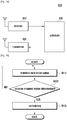
- FIG. 1 is a block diagram illustrating the configuration of a mobile communication according to an embodiment of the present invention. The description is made under the assumption that the transmitter is a base station and the receiver is a user terminal.
- the mobile communication system includes a base station 10 and a terminal 20.
- the base station 10 provides a communication service. That is, the base station 10 performs scheduling to allocate downlink and uplink channels.
- the base station 10 transmits Reference signals and data on downlink channels.
- the terminal 20 uses the communication service. That is, the terminal 20 checks the downlink channel with the reference signals.
- the terminal 20 also feeds back the channel status information of the downlink channel to the base station 10.
- the description is directed to the feedback method for the rank-restricted transmission scheme and rank-unrestricted transmission scheme, the present invention is not limited thereto.
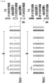
- FIG. 2 is a diagram illustrating a channel status information feedback method for uplink channel according to the first example in the mobile communication system supporting both the rank-restricted transmission scheme and rank-unrestricted transmission scheme.
- each of both the channel status information for the rank-restricted transmission scheme and the channel status information for the rank-unrestricted transmission scheme includes RI, subband CQI/PMI, and wideband CQI/PMI.
- the RI is fed back at an interval of RP, and the transmission interval between the wideband CQI/PMI and the subband CQI/PMI is P, however, the subband CQI/PMI is transmitted more frequently as compared to the wideband CQI/PMI.
- the time durations for the rank-restricted transmission scheme and the rank-unrestricted transmission scheme are identical with each other and each of the times durations is arranged periodically.
- the same type of channel status information is fed back for the rank-restricted transmission scheme and rank-unrestricted transmission scheme for the same duration.
- the subband CQI/PMI for the rank-restricted transmission scheme can be fed back.
- different types of channel status information can be fed back for the rank-unrestricted transmission scheme and the rank-restricted transmission scheme in the same time duration.
- the subband CQI/PMI for the rank-restricted transmission scheme can be fed back.
- FIG. 3 is a diagram illustrating channel status information feedback method for uplink channel according to the second example in the mobile communication system supporting both the rank-restricted transmission scheme and rank-unrestricted transmission scheme.
- the feedback of the channel status information for the rank-non-restricted transmission scheme is same as the example described with reference to FIG. 1 . Nevertheless, the transmission interval of the channel status information feedback for the rank-restricted transmission scheme, i.e. MP, can differ from the P described with reference to FIG. 1 . That is, the transmission interval of the channel status information for the rank-restricted transmission scheme can be longer or shorter than that of the rank-unrestricted transmission scheme.
- the time durations for the rank-unrestricted transmission scheme and the rank-restricted transmission scheme on the uplink channel are identical with each other and arranged periodically.
- both the channel status information of the rank-unrestricted transmission scheme and channel status information of the rank-restricted transmission scheme can be fed back in the same time duration. Also, the channel status information of one of both the rank-unrestricted transmission scheme and rank-restricted transmission scheme is fed back while the channel status information of the other is not transmitted.
- FIG. 4 is a diagram illustrating channel status information feedback method according to the third example in the mobile communication system supporting both the rank-restricted transmission scheme and rank-unrestricted transmission scheme.
- the channel status information feedback for both the rank-restricted transmission scheme and rank-unrestricted transmission schemes are performed on one uplink channel resource.
- the feedbacks of channel status information for the rank-restricted transmission scheme and the channel status information feedback for the ran-unrestricted transmission scheme are transmitted at their individual transmission intervals that are different from each other.
- the time durations for the rank-restricted transmission scheme and the rank-unrestricted transmission scheme on the uplink channel are arranged periodically. In this manner, the channel status information of one of the rank-unrestricted transmission scheme and rank-restricted transmission scheme can be fed back.
- FIG 5 is a diagram illustrating channel status information feedback method according to the fourth example in the mobile communication system supporting both the rank-restricted scheme and rank-unrestricted transmission scheme.
- the time duration of the rank-unrestricted transmission scheme and the time duration of the rank-restricted transmission scheme differ from each other on uplink channel.
- the time durations of the rank-unrestricted transmission scheme and the rank-restricted transmission scheme can occupy different resources on the uplink channel.
- the time durations for the rank-restricted transmission scheme are arranged periodically, and the time durations for the rank-unrestricted transmission scheme are arranged periodically.
- the channel status information feedback interval for the rank-unrestricted transmission scheme and the channel status information feedback transmission scheme for the rank-restricted transmission scheme can differ from each other.
- the common factor of the channel status information feedback methods is, when feeding back the channel status information for two different transmission schemes (e.g., MU-MIMO and SU-MIMO of 3GPP LTE-A) to transmit all of the channel status information of RI and CQI/PMI.
- two different transmission schemes e.g., MU-MIMO and SU-MIMO of 3GPP LTE-A
- the method for acquiring the channel status information for a transmission scheme from the channel status information fed back for another transmission scheme is more efficient.
- the rank information for the rank-restricted transmission scheme can acquired the RI feedback for the rank-unrestricted transmission method, such that there is a room for improvement in the present invention.
- the embodiment of the present invention proposes a channel status transmission/reception method and apparatus for acquiring the rank information for the rank-restricted transmission scheme from the RI fed back for the rank-unrestricted transmission scheme without feeding back the RI for the rank-restricted transmission scheme to reduce the feedback overhead in the cellular mobile communication system supporting both the rank-restricted transmission scheme and the rank-unrestricted transmission scheme.
- the channel status information feedback method according to the second embodiment of the present invention is described with reference to FIGs. 6 to 10 . Although the descriptions are made under the assumption of the feedback method for the rank-restricted transmission scheme and the rank-unrestricted transmission scheme, the present invention is not limited thereto.
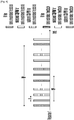
- FIG. 6 is a diagram illustrating channel status information feedback method according to the first example of the embodiment of the present invention.
- the RI, subband CQI/PMI, and wideband CQI/PMI for the rank-unrestricted transmission scheme are fed back and the subband CQI/PMI and wideband CQI/PMI for the rank-restricted transmission scheme.
- one of the subband CQI/PMI and wideband CQI/PMI for the rank-unrestricted transmission scheme and one of the subband CQI/PMI and wideband CQI/PMI for the rank-restricted transmission scheme are transmitted at the same timing.
- the RI for the rank-restricted transmission scheme is not fed back. Accordingly, the rank information for the subband CQI/PMI and wideband CQI/PMI for the rank-restricted transmission scheme is acquired from the most recent RI fed back for the rank-unrestricted transmission scheme.
- the RI for the rank-unrestricted transmission scheme is fed back at an interval of RP, and the subband CQI/PMIs and the wideband CQI/PMIs for the rank-unrestricted transmission scheme and rank-restricted transmission scheme are fed back at an interval of P respectively.
- the wideband CQI/PMI is fed back more frequently than the subband CQI/PMI.
- the time durations for the rank-unrestricted transmission scheme and the rank-restricted transmission scheme are identical with each on uplink channel and arranged periodically. Also, the same time duration can be occupied for the same type channel status information for the rank-restricted transmission scheme and the rank-unrestricted transmission scheme.
- the subband CQI/PMI for the rank-restricted transmission scheme can be fed back.
- the same time duration can be occupied for the transmission of the different type channel status information for the rank-unrestricted transmission scheme and the rank-restricted transmission scheme.
- the wideband CQI/PMI for the rank-restricted transmission scheme can be fed back.
- FIG. 7 is a diagram illustrating the feedback method according to the second example of the embodiment of the present invention.
- the channel status information feedback for the rank-unrestricted transmission scheme is same as the exemplary case described with reference to FIG. 6 .
- the channel status feedback interval, i.e. MP for the rank-restricted transmission scheme differs from the channel information feedback interval, i.e. P, for the rank-unrestricted transmission scheme.
- the RI for the rank-restricted transmission scheme is not fed back.
- the rank information for the rank-restricted transmission scheme is acquired from the RI most recently fed back for the rank-unrestricted transmission scheme.
- the time durations for the rank-unrestricted transmission scheme and the rank-restricted transmission scheme are identical with each other and arranged periodically on the uplink channel.
- both the channel information for the rank-unrestricted transmission scheme and the channel status information for the rank-restricted transmission scheme are fed back in specific time duration.
- the channel status information of one of the rank-unrestricted transmission scheme and the rank-restricted transmission scheme can be fed back in other time duration while the channel information of the other is not fed back.
- FIG. 8 is a diagram illustrating a feedback method according to the third example of the embodiment of the present invention.
- the channel information feedback for the rank-restricted transmission scheme and the channel information feedback for the rank-unrestricted transmission scheme are both transmitted on a single uplink channel resource.
- the RI for the rank-unrestricted transmission scheme is transmitted but not the RI for the rank-restricted transmission scheme is transmitted separately.
- the rank information for the rank-restricted transmission scheme is acquired from the RI most recently fed back for the rank-unrestricted transmission scheme.
- the time durations for the rank-unrestricted transmission scheme and the rank-restricted transmission scheme are arranged periodically on the uplink channel. In this manner, the channel information of one of the rank-unrestricted transmission scheme and the rank-restricted transmission scheme can be fed back in each time duration on the uplink channel.
- FIG. 9 is a diagram illustrating the feedback method for the fourth example of the embodiment of the present invention.
- the time duration for the rank-unrestricted transmission scheme and the time duration for the rank-restricted transmission scheme are different from each other on the uplink channel.
- the time duration of the rank-unrestricted transmission scheme and the time duration of the rank-restricted transmission scheme can occupy different resources on the uplink channel.
- the time durations for the rank-unrestricted transmission scheme are arranged periodically, and the time durations for the rank-restricted transmission scheme are arranged periodically.
- the transmission interval of the channel status information feedback for the rank-restricted transmission scheme and the transmission interval of the channel status information feedback for the rank-unrestricted transmission scheme can be different from each other.
- the RI for the rank-restricted transmission scheme may not be transmitted as in the above described exemplary cases.
- the rank information for the rank-restricted transmission scheme can be acquired from the RI most recently transmitted for the rank-unrestricted transmission scheme.
- the present invention is not limited thereto. That is, the feedback method according to the embodiment of the present invention can be generalized as shown in FIG. 10 .
- the key issue of the feedback method according to the embodiment of the present invention is, when two or more different transmission schemes are used, to feed back the rank information for one of the multiple transmission scheme such that the rank information for other transmission scheme is estimated from the received rank information.
- the channel status informations for the different transmission scheme occupy different uplink channel resources
- the present invention encompasses the cases where the channel status informations for all the transmission schemes are transmitted in different time durations on the same uplink channel.
- the feedback method of the present invention can be applied regardless of whether there is the transmission scheme restricted in rank among the multiple transmission schemes or not and whether the transmission ranks supported by the multiple transmission schemes are identical with or different from each other. In such a case, however, it is preferred to feed back the RI of the transmission scheme supporting the highest transmission rank among the multiple transmission schemes.
- the RI of the transmission scheme supporting the highest transmission rank among the N transmission schemes is the highest one such that the RI for the transmission scheme 1 is fed back.
- the rank information for each of 2 nd , ..., N th transmission schemes can be acquired from the RI fed back for the transmission scheme 1.
- the R 1 is the channel rank information acquired from the RI fed most recently back for the transmission scheme 1.
- the CQIs/PMIs of the transmission schemes of which RIs are not fed back are determined and fed back in consideration of the rank acquired through the above-described process.
- FIG. 11 is a block diagram illustrating an internal configuration of a transmission apparatus for performing the feedback method according to the embodiment of the present invention.
- the transmission apparatus can be implemented as a part of the terminal.
- the transmission apparatus 600 includes a receiver 610, a channel estimator 620, a channel analyzer 630, a feedback information generator 640, and a transmitter 650.
- the receiver 610 receives the reference signals on the downlink channel. At this time, the receiver 610 receives the reference signals from the base station 10.
- the channel estimator 620 estimates the downlink channel base on the reference signals.
- the channel analyzer 630 analyzes the downlink channels and selects at least two transmission schemes and the RI, subband CQI/PMI, and wideband CQI/PMI per transmission scheme.
- the feedback information generator 640 generates the channel status information according to the downlink channel analysis result. At this time, the feedback information generator 640 combines the rank informations for the individual transmission schemes to generate the RI for one of the transmission schemes.
- the transmitter 650 feeds back the channel status information on the uplink channel.
- the transmitter 650 transmits the channel status information for the individual transmission schemes to the base station 10 under the control of the feedback information generator 640. At this time, the transmitter 650 transmits a combined RI corresponding to one of the transmission schemes without transmission of separate RIs for other transmission schemes. Here, the transmitter 650 can transmit the channel status information as depicted in one of FIGs. 6 to 10 .
- FIG. 12 is a flowchart illustrating the operation procedure of the transmission apparatus for the feedback method according to the embodiment of the present invention.
- the transmission apparatus 600 detects the receipt of the reference signal at step 711 and estimates downlink channel using the reference signal at step 713.
- the transmission apparatus 600 analyzes the downlink channel to measure the status of the downlink channel at step S715.
- the transmission apparatus 600 selects at least two transmission schemes and the RI, subband CQI/PMI, and wideband CQI/PMI per transmission scheme.
- the transmission apparatus 600 generates the channel status information according to the downlink channel analysis result at step S717.
- the transmission apparatus 600 combines the rank informations corresponding to individual transmission schemes to generate the RI for one of the transmission schemes.
- the transmission apparatus 600 transmits the channel status information on the uplink channel at step 719. That is, the transmitter 600 feeds back the channel status information for each transmission scheme to the base station 10.
- the transmission apparatus 600 transmits a combined RI corresponding to one of the transmission schemes without separate transmission of the RIs for the rest transmission schemes.
- the channel status information transmission procedure of the transmission apparatus 600 is described hereinafter.
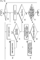
- FIG. 13 is a flowchart illustrating a channel status information transmission procedure of FIG. 12 .
- the transmission apparatus 600 compares maximum transmission ranks of at least two transmission schemes and checks whether it is the timing to feed back the channel status information for the transmission scheme having the highest transmission rank at step 721.
- the transmission apparatus 600 checks whether it is a timing for feedback of the RI at step 723. If it is the timing for feedback of the RI, the transmission apparatus 600 feeds back the RI at step 725. Otherwise if it is not the timing for the feedback of the RI at step 723, the transmission apparatus 600 checks whether it is a timing for feedback of the subband CQI/PMI at step S727. If it is the timing for the feedback of the subband CQI/PMI at step 727, the transmission apparatus 600 feeds back the subband CQI/PMI at step S729.
- the transmission apparatus 600 feeds back the wideband CQI/PMI at step 831. Meanwhile, if it is not the timing for the feedback of the channel status information for the transmission scheme having the highest maximum transmission rank at step 721, the transmission apparatus 600 checks whether it is a timing for feedback of subband CQI/PMI at step 733. If it is the timing for the feedback of the subband CQI/PMI at step 733, the transmission apparatus 600 feeds back the subband CQI/PMI based on the rank information determined based on the RI most recently fed back for the transmission scheme according to the above-described method.
- the transmission apparatus 600 feeds back the subband CQI/PMI for the transmission scheme of which maximum transmission rank is not the highest one using the RI most recently fed back. If it is not the timing of the feedback of the subband CQI/PMI at step 733, the transmission apparatus 600 feeds back the wideband CQI/PMI based on the rank information determined with the RI most recently fed back for the transmission scheme feeding back the RI at step S737. That is, the transmission apparatus 600 feeds back the wideband CQI/PMI for the transmission scheme of which maximum transmission rank is not the highest one using the RI most recently fed back for the transmission scheme feeding back the RI.
- FIG. 14 is a block diagram illustrating internal configuration of a reception apparatus for performing the feedback method according to the embodiment of the present invention.
- the reception apparatus can be implemented as a part of the base station.
- the reception apparatus 800 includes a receiver 810, a scheduler 820, and a transmitter 830.
- the receiver 810 receives the channel status information on the uplink channel. That is, the receiver 810 receives the channel status informations corresponding to at least two transmission schemes. At this time, the receiver 810 receives the combined rank information for one of the transmission schemes.
- the scheduler 820 performs scheduling with the channel status information. At this time, the scheduler 820 calculates the rank per transmission scheme with the combined rank information for the transmission schemes.
- the scheduler 820 can select appropriate modulation and coding scheme according to the channel status information and perform scheduling based on the modulation coding scheme.
- the transmitter 830 transmits the data on the downlink channel. That is, the transmitter 830 transmits the data as scheduled by the scheduler 820.
- FIG. 15 is a flowchart illustrating operation procedure of the reception apparatus for the feedback method according to the embodiment of the present invention.
- the transmission apparatus 800 transmits the reference signal on the downlink channel at step 911.
- the transmission apparatus 800 transmits the reference signals as scheduled based on the channel status information received previously from the terminal 20. At this time, the reference signals are transmitted on the downlink channel.
- the reception apparatus 800 can further transmit data on the downlink channel as scheduled. If the channel status information is received on the uplink channel, the reception apparatus 800 detects the receipt of the channel status information at step 913 and performs scheduling according to the channel status information at step 915. At this time, the reception apparatus 800 can receive the channel status information corresponding to at least two transmission schemes from the terminal 20. Here, the reception apparatus 800 receives the rank information combined for the transmission schemes.
- the reception apparatus 800 calculates the rank per transmission scheme using the combined rank information for the transmission schemes to determine the transmission scheme to be applied for the downlink channel. That is, the reception apparatus 800 selects an appropriate modulation and coding scheme according to the channel status information. The reception apparatus 800 also performs scheduling on the downlink channel according to the transmission scheme. The scheduling procedure of the reception apparatus 800 is described in more detail hereinafter.
- FIG. 16 is a flowchart illustrating a scheduling procedure of FIG. 15 .
- the reception apparatus 800 determines whether to perform transmission using the transmission scheme for which no rank information is fed back at step 917. If it is determined to use the transmission scheme for which no rank information is fed back at step 917, the reception apparatus 800 calculates the rank using the RI most recently fed back for the transmission scheme at step 919. Next, the reception apparatus 800 performs scheduling based on the channel status information fed back, i.e., the CQI/PMI and the calculated rank, at step 921. Otherwise if it is determined to not use the transmission scheme for which no rank information is fed back at step 917, the reception apparatus 800 performs scheduling at step 923 based on the channel status information, i.e. RI and CQI/PMP, fed back.
- the channel status information i.e. RI and CQI/PMP
- the terminal 20 feeds back the rank informations for multiple transmission schemes in combined manner so as to reduce the overhead at the base station 10. That is, the channel status information overhead can be mitigated at the base station 10.
Landscapes
- Engineering & Computer Science (AREA)
- Computer Networks & Wireless Communication (AREA)
- Signal Processing (AREA)
- Quality & Reliability (AREA)
- Physics & Mathematics (AREA)
- Mathematical Physics (AREA)
- Mobile Radio Communication Systems (AREA)
Claims (15)
- Verfahren zum Übertragen von Kanalzustandsinformationen eines Endgeräts in einem drahtlosen Kommunikationssystem, wobei das Verfahren Folgendes umfasst:Empfangen eines Referenzsignals (711) von einer Basisstation;Identifizieren einer ersten Rangangabe für ein erstes Übertragungsschema, das mit einem einzelnen Benutzer assoziiert ist, und einer zweiten Rangangabe für ein zweites Übertragungsschema, das mit einem Multibenutzer assoziiert ist, basierend auf dem Referenzsignal;Bestimmen der kombinierten Rangangabe basierend auf der ersten Rangangabe und der zweiten Rangangabe;Erzeugen von Kanalzustandsinformationen für das zweite Übertragungsschema, das mit dem Multibenutzer assoziiert ist, basierend auf der kombinierten Rangangabe (717); undÜbertragen der erzeugten Kanalzustandsinformationen für das zweite Übertragungsschema (719) an die Basisstation.
- Verfahren nach Anspruch 1, wobei das Erzeugen der Kanalzustandsinformationen für das zweite Übertragungsschema Folgendes umfasst:
Erzeugen der Kanalzustandsinformationen für das zweite Übertragungsschema basierend auf der kombinierten Rangangabe und einem höchsten Wert von unterstützbaren unter dem ersten Übertragungsschema und dem zweiten Übertragungsschema. - Verfahren nach Anspruch 1, wobei die Kanalzustandsinformationen eine Kanalqualitätsanzeige, CQI, und/oder eine Vorcodierungsmatrixanzeige, PMI, für das zweite Übertragungsschema umfassen und das Übertragen der erzeugten Kanalzustandsinformationen für das zweite Übertragungsschema Folgendes umfasst:Übertragen der kombinierten Rangangabe über das erste Übertragungsschema,Übertragen einer CQI und/oder einer PMI für das zweite Übertragungsschema über das zweite Übertragungsschema.
- Verfahren zum Empfangen von Kanalzustandsinformationen einer Basisstation in einem drahtlosen Kommunikationssystem, wobei das Verfahren Folgendes umfasst:Übertragen eines Referenzsignals (911) an ein Endgerät;Erfassen einer kombinierten Rangangabe basierend auf einer ersten Rangangabe für ein erstes Übertragungsschema, das mit einem einzelnen Benutzer assoziiert ist, und einer zweiten Rangangabe für ein zweites Übertragungsschema, das mit einem Multibenutzer assoziiert ist, wobei die erste Rangangabe und die zweite Rangangabe basierend auf dem Referenzsignal identifiziert werden;Empfangen von Kanalzustandsinformationen für das zweite Übertragungsschema, das mit dem Multibenutzer assoziiert ist, der basierend auf der kombinierten Rangangabe (913) identifiziert wird; undPlanen des Downlink-Kanals in Bezug auf das zweite Übertragungsschema basierend auf den empfangenen Kanalzustandsinformationen (915).
- Verfahren nach Anspruch 4, wobei das Planen Folgendes umfasst:
Planen des Downlink-Kanals in Bezug auf das zweite Übertragungsschema basierend auf einem Rang, der basierend auf der kombinierten Rangangabe berechnet wird. - Verfahren nach Anspruch 5, wobei das Planen des Downlink-Kanals Folgendes umfasst:
Planen des Downlink-Kanals in Bezug auf das zweite Übertragungsschema durch Identifizieren des Ranges eines der Übertragungsschemata unter Verwenden der kombinierten Rangangabe. - Verfahren nach Anspruch 4, wobei die kombinierte Rangangabe basierend auf einem höchsten Wert von unterstützbaren Rängen unter dem ersten Übertragungsschema und dem zweiten Übertragungsschema identifiziert wird.
- Verfahren nach Anspruch 4, wobei die Kanalzustandsinformationen eine Kanalqualitätsanzeige, CQI, und/oder eine Vorcodierungsmatrixanzeige, PMI, für das zweite Übertragungsschema umfassen, und
wobei das Empfangen der Kanalzustandsinformationen für das zweite Übertragungsschema Folgendes umfasst:Empfangen der kombinierten Rangangabe über das erste Übertragungsschema, undEmpfangen einer CQI und/oder einer PMI für das zweite Übertragungsschema über das zweite Übertragungsschema. - Übertragungsvorrichtung eines Endgeräts, welche Folgendes umfasst:einen Transceiver (610, 650), der konfiguriert ist, um mindestens ein Signal zu übertragen und zu empfangen;eine Steuerung, die mit dem Transceiver gekoppelt und konfiguriert ist zum:Empfangen eines Referenzsignals von einer Basisstation,Identifizieren einer ersten Rangangabe für ein erstes Übertragungsschema, das mit einem einzelnen Benutzer assoziiert ist, und einer zweiten Rangangabe für ein zweites Übertragungsschema, das mit einem Multibenutzer assoziiert ist, basierend auf dem Referenzsignal,Bestimmen einer kombinierten Rangangabe basierend auf der ersten Rangangabe und der zweiten Rangangabe,Erzeugen von Kanalinformationen für das zweite Übertragungsschema, das mit dem Multibenutzer assoziiert ist, basierend auf der kombinierten Rangangabe, undÜbertragen der erzeugten Kanalzustandsinformationen für das zweite Übertragungsschema an die Basisstation.
- Übertragungsvorrichtung nach Anspruch 9, wobei die Steuerung ferner konfiguriert ist zum:
Erzeugen der Kanalzustandsinformationen für das zweite Übertragungsschema basierend auf der kombinierten Rangangabe und einem höchsten Wert von unterstützbaren unter dem ersten Übertragungsschema und dem zweiten Übertragungsschema. - Übertragungsvorrichtung nach Anspruch 9, wobei die Kanalzustandsinformationen eine Kanalqualitätsanzeige, CQI, und/oder eine Vorcodierungsmatrixanzeige, PMI, für das zweite Übertragungsschema umfassen, und
wobei die Steuerung ferner konfiguriert ist zum:Übertragen der kombinierten Rangangabe über das erste Übertragungsschema, undÜbertragen der CQI und/oder der PMI für das zweite Übertragungsschema über das zweite Übertragungsschema. - Empfangsvorrichtung einer Basisstation, welche Folgendes umfasst:einen Transceiver (810, 830), der konfiguriert ist, um mindestens ein Signal zu übertragen und zu empfangen;eine Steuerung, die mit dem Transceiver gekoppelt und konfiguriert ist zum:Übertragen eines Referenzsignals an ein Endgerät,Erfassen einer kombinierten Rangangabe basierend auf einer ersten Rangangabe für ein erstes Übertragungsschema, das mit einem einzelnen Benutzer assoziiert ist, und einer zweiten Rangangabe für ein zweites Übertragungsschema, das mit einem Multibenutzer assoziiert ist, wobei die erste Rangangabe und die zweite Rangangabe basierend auf dem Referenzsignal identifiziert werdenEmpfangen von Kanalzustandsinformationen für das zweite Übertragungsschema, das mit dem Multibenutzer assoziiert ist, der basierend auf der kombinierten Rangangabe identifiziert wird, undPlanen des Downlink-Kanals in Bezug auf das zweite Übertragungsschema basierend auf den empfangenen Kanalzustandsinformationen.
- Empfangsvorrichtung nach Anspruch 12, wobei die Steuerung ferner konfiguriert ist, um den Downlink-Kanal in Bezug auf das zweite Übertragungsschema zu planen, basierend auf einem Rang, der basierend auf der kombinierten Rangangabe berechnet wird, indem der Rang für das eine der Übertragungsschemata unter Verwenden der kombinierten Rangangabe identifiziert wird.
- Empfangsvorrichtung nach Anspruch 12, wobei die kombinierte Rangangabe basierend auf einem höchsten Wert von unterstützbaren Rängen unter dem ersten Übertragungsschema und dem zweiten Übertragungsschema identifiziert wird.
- Empfangsvorrichtung nach Anspruch 12, wobei die Kanalzustandsinformationen eine Kanalqualitätsanzeige, CQI, und/oder eine Vorcodierungsmatrixanzeige, PMI für das zweite Übertragungsschema umfassen, und
wobei die Steuerung ferner konfiguriert ist zum:Empfangen der kombinierten Rangangabe über das erste Übertragungsschema, undEmpfangen einer CQI und/oder einer PMI für das zweite Übertragungsschema über das zweite Übertragungsschema.
Applications Claiming Priority (2)
| Application Number | Priority Date | Filing Date | Title |
|---|---|---|---|
| KR1020100027671A KR101657944B1 (ko) | 2010-03-29 | 2010-03-29 | 이동통신 시스템에서 채널 상태 정보 송수신 방법 및 장치 |
| PCT/KR2011/002077 WO2011122799A2 (en) | 2010-03-29 | 2011-03-25 | Apparatus and method for sending and receiving channel state information in communication system |
Publications (3)
| Publication Number | Publication Date |
|---|---|
| EP2553969A2 EP2553969A2 (de) | 2013-02-06 |
| EP2553969A4 EP2553969A4 (de) | 2017-08-16 |
| EP2553969B1 true EP2553969B1 (de) | 2020-12-09 |
Family
ID=44720408
Family Applications (1)
| Application Number | Title | Priority Date | Filing Date |
|---|---|---|---|
| EP11762971.7A Active EP2553969B1 (de) | 2010-03-29 | 2011-03-25 | Vorrichtung und verfahren zum senden und empfangen von kanalstatusinformationen in einem drahtlosen kommunikationssystem |
Country Status (4)
| Country | Link |
|---|---|
| US (1) | US9628218B2 (de) |
| EP (1) | EP2553969B1 (de) |
| KR (1) | KR101657944B1 (de) |
| WO (1) | WO2011122799A2 (de) |
Families Citing this family (5)
| Publication number | Priority date | Publication date | Assignee | Title |
|---|---|---|---|---|
| KR101901434B1 (ko) * | 2011-09-23 | 2018-09-27 | 삼성전자 주식회사 | 협력 통신 시스템을 위한 피드백 송수신 방법 및 장치 |
| GB2496458A (en) * | 2011-11-14 | 2013-05-15 | Renesas Mobile Corp | Transmission of channel state information |
| US9876655B2 (en) * | 2013-08-16 | 2018-01-23 | Mediatek Singapore Pte. Ltd. | Precoding-codebook-based secure uplink in LTE |
| WO2015165084A1 (zh) * | 2014-04-30 | 2015-11-05 | 华为技术有限公司 | 非授权频谱的调度方法、设备及用户设备ue |
| US10200102B2 (en) * | 2015-11-13 | 2019-02-05 | Qualcomm Incorporated | Channel station information reporting and transmission mode for enhanced machine type communication |
Family Cites Families (9)
| Publication number | Priority date | Publication date | Assignee | Title |
|---|---|---|---|---|
| KR101151817B1 (ko) | 2006-05-03 | 2012-06-01 | 한국전자통신연구원 | 이동 통신 시스템에서의 상향 링크 제어 정보 전송 방법 |
| WO2008051038A1 (en) | 2006-10-26 | 2008-05-02 | Lg Electronics Inc. | Method for reporting channel information in multiple antenna system |
| KR101306729B1 (ko) | 2007-02-05 | 2013-09-11 | 엘지전자 주식회사 | 피드백 정보 송수신 방법 |
| US7885211B2 (en) * | 2007-10-26 | 2011-02-08 | Texas Instruments Incorporated | Selective rank CQI and PMI feedback in wireless networks |
| US8811353B2 (en) * | 2008-04-22 | 2014-08-19 | Texas Instruments Incorporated | Rank and PMI in download control signaling for uplink single-user MIMO (UL SU-MIMO) |
| WO2010002691A2 (en) * | 2008-06-30 | 2010-01-07 | Interdigital Patent Holdings, Inc. | Method and apparatus for performing multiple-input multiple-output wireless communications |
| EP2164201B1 (de) * | 2008-09-15 | 2019-10-30 | Telefonaktiebolaget LM Ericsson (publ) | Verfahren zur Bereitstellung eines physisch gemeinsam benutzten Aufwärtskanal-Bitstroms |
| US8526519B2 (en) * | 2009-12-14 | 2013-09-03 | Texas Instruments Incorporated | Multi-rank precoding matrix indicator (PMI) feedback in a multiple-input multiple-output (MIMO) system |
| US8644422B2 (en) * | 2010-02-12 | 2014-02-04 | Blackberry Limited | Low overhead PMI and CQI feedback and pairing schemes for MU-MIMO |
-
2010
- 2010-03-29 KR KR1020100027671A patent/KR101657944B1/ko not_active Expired - Fee Related
-
2011
- 2011-03-25 EP EP11762971.7A patent/EP2553969B1/de active Active
- 2011-03-25 US US13/582,201 patent/US9628218B2/en active Active
- 2011-03-25 WO PCT/KR2011/002077 patent/WO2011122799A2/en not_active Ceased
Non-Patent Citations (1)
| Title |
|---|
| None * |
Also Published As
| Publication number | Publication date |
|---|---|
| WO2011122799A3 (en) | 2012-01-12 |
| US20120320832A1 (en) | 2012-12-20 |
| EP2553969A4 (de) | 2017-08-16 |
| KR20110108466A (ko) | 2011-10-06 |
| EP2553969A2 (de) | 2013-02-06 |
| US9628218B2 (en) | 2017-04-18 |
| WO2011122799A2 (en) | 2011-10-06 |
| KR101657944B1 (ko) | 2016-09-20 |
Similar Documents
| Publication | Publication Date | Title |
|---|---|---|
| US11064506B2 (en) | Method and apparatus for transmitting and receiving feedback for cooperative communication system | |
| US11057902B2 (en) | Channel rank updates in multiple-input multiple-output communication systems | |
| US9838103B2 (en) | Method and apparatus for transmitting and receiving feedback information in a mobile communication system | |
| EP2078345B1 (de) | Verfahren und vorrichtung zum senden/empfangen von rückmeldeinformationen in einem drahtlosen paketdatenkommunikationssystem | |
| EP2612448B1 (de) | Kanalstatusrückkopplung für mehrzellen-mimo | |
| EP2439981B1 (de) | Verfahren und vorrichtung zum senden und empfangen von feedbackinformationen für interzelluläre kooperative übertragung in einem zellulären drahtlosen kommunikationssystem | |
| JP6249503B2 (ja) | 通信システムにおけるフィードバック情報を送受信する方法及び装置 | |
| EP2127222B1 (de) | Senden und empfangen von cqi- und pmi-feedback informationen | |
| JP4719728B2 (ja) | 通信システム、ユーザ装置及び送信方法 | |
| US8457008B2 (en) | Method of transmitting feedback information for performing collaborative MIMO | |
| JP2009542157A (ja) | 閉ループ多重アンテナシステムにおけるデータ送受信装置及びその方法 | |
| EP2553969B1 (de) | Vorrichtung und verfahren zum senden und empfangen von kanalstatusinformationen in einem drahtlosen kommunikationssystem | |
| EP2707979B1 (de) | Kooperative mehrpunktlösung für voip | |
| JP5337835B2 (ja) | 通信システム、ユーザ装置及び送信方法 | |
| JP5706935B2 (ja) | 移動通信システムにおける基地局装置 |
Legal Events
| Date | Code | Title | Description |
|---|---|---|---|
| PUAI | Public reference made under article 153(3) epc to a published international application that has entered the european phase |
Free format text: ORIGINAL CODE: 0009012 |
|
| 17P | Request for examination filed |
Effective date: 20120827 |
|
| AK | Designated contracting states |
Kind code of ref document: A2 Designated state(s): AL AT BE BG CH CY CZ DE DK EE ES FI FR GB GR HR HU IE IS IT LI LT LU LV MC MK MT NL NO PL PT RO RS SE SI SK SM TR |
|
| DAX | Request for extension of the european patent (deleted) | ||
| A4 | Supplementary search report drawn up and despatched |
Effective date: 20170718 |
|
| RIC1 | Information provided on ipc code assigned before grant |
Ipc: H04W 72/12 20090101ALI20170712BHEP Ipc: H04W 24/10 20090101AFI20170712BHEP |
|
| STAA | Information on the status of an ep patent application or granted ep patent |
Free format text: STATUS: EXAMINATION IS IN PROGRESS |
|
| 17Q | First examination report despatched |
Effective date: 20180314 |
|
| GRAP | Despatch of communication of intention to grant a patent |
Free format text: ORIGINAL CODE: EPIDOSNIGR1 |
|
| STAA | Information on the status of an ep patent application or granted ep patent |
Free format text: STATUS: GRANT OF PATENT IS INTENDED |
|
| INTG | Intention to grant announced |
Effective date: 20200921 |
|
| GRAS | Grant fee paid |
Free format text: ORIGINAL CODE: EPIDOSNIGR3 |
|
| GRAA | (expected) grant |
Free format text: ORIGINAL CODE: 0009210 |
|
| STAA | Information on the status of an ep patent application or granted ep patent |
Free format text: STATUS: THE PATENT HAS BEEN GRANTED |
|
| AK | Designated contracting states |
Kind code of ref document: B1 Designated state(s): AL AT BE BG CH CY CZ DE DK EE ES FI FR GB GR HR HU IE IS IT LI LT LU LV MC MK MT NL NO PL PT RO RS SE SI SK SM TR |
|
| REG | Reference to a national code |
Ref country code: GB Ref legal event code: FG4D |
|
| REG | Reference to a national code |
Ref country code: AT Ref legal event code: REF Ref document number: 1344611 Country of ref document: AT Kind code of ref document: T Effective date: 20201215 Ref country code: CH Ref legal event code: EP |
|
| REG | Reference to a national code |
Ref country code: DE Ref legal event code: R096 Ref document number: 602011069593 Country of ref document: DE |
|
| REG | Reference to a national code |
Ref country code: IE Ref legal event code: FG4D |
|
| PG25 | Lapsed in a contracting state [announced via postgrant information from national office to epo] |
Ref country code: NO Free format text: LAPSE BECAUSE OF FAILURE TO SUBMIT A TRANSLATION OF THE DESCRIPTION OR TO PAY THE FEE WITHIN THE PRESCRIBED TIME-LIMIT Effective date: 20210309 Ref country code: RS Free format text: LAPSE BECAUSE OF FAILURE TO SUBMIT A TRANSLATION OF THE DESCRIPTION OR TO PAY THE FEE WITHIN THE PRESCRIBED TIME-LIMIT Effective date: 20201209 Ref country code: FI Free format text: LAPSE BECAUSE OF FAILURE TO SUBMIT A TRANSLATION OF THE DESCRIPTION OR TO PAY THE FEE WITHIN THE PRESCRIBED TIME-LIMIT Effective date: 20201209 Ref country code: GR Free format text: LAPSE BECAUSE OF FAILURE TO SUBMIT A TRANSLATION OF THE DESCRIPTION OR TO PAY THE FEE WITHIN THE PRESCRIBED TIME-LIMIT Effective date: 20210310 |
|
| REG | Reference to a national code |
Ref country code: AT Ref legal event code: MK05 Ref document number: 1344611 Country of ref document: AT Kind code of ref document: T Effective date: 20201209 |
|
| PG25 | Lapsed in a contracting state [announced via postgrant information from national office to epo] |
Ref country code: LV Free format text: LAPSE BECAUSE OF FAILURE TO SUBMIT A TRANSLATION OF THE DESCRIPTION OR TO PAY THE FEE WITHIN THE PRESCRIBED TIME-LIMIT Effective date: 20201209 Ref country code: SE Free format text: LAPSE BECAUSE OF FAILURE TO SUBMIT A TRANSLATION OF THE DESCRIPTION OR TO PAY THE FEE WITHIN THE PRESCRIBED TIME-LIMIT Effective date: 20201209 Ref country code: BG Free format text: LAPSE BECAUSE OF FAILURE TO SUBMIT A TRANSLATION OF THE DESCRIPTION OR TO PAY THE FEE WITHIN THE PRESCRIBED TIME-LIMIT Effective date: 20210309 |
|
| REG | Reference to a national code |
Ref country code: NL Ref legal event code: MP Effective date: 20201209 |
|
| PG25 | Lapsed in a contracting state [announced via postgrant information from national office to epo] |
Ref country code: NL Free format text: LAPSE BECAUSE OF FAILURE TO SUBMIT A TRANSLATION OF THE DESCRIPTION OR TO PAY THE FEE WITHIN THE PRESCRIBED TIME-LIMIT Effective date: 20201209 Ref country code: HR Free format text: LAPSE BECAUSE OF FAILURE TO SUBMIT A TRANSLATION OF THE DESCRIPTION OR TO PAY THE FEE WITHIN THE PRESCRIBED TIME-LIMIT Effective date: 20201209 |
|
| REG | Reference to a national code |
Ref country code: LT Ref legal event code: MG9D |
|
| PG25 | Lapsed in a contracting state [announced via postgrant information from national office to epo] |
Ref country code: SK Free format text: LAPSE BECAUSE OF FAILURE TO SUBMIT A TRANSLATION OF THE DESCRIPTION OR TO PAY THE FEE WITHIN THE PRESCRIBED TIME-LIMIT Effective date: 20201209 Ref country code: PT Free format text: LAPSE BECAUSE OF FAILURE TO SUBMIT A TRANSLATION OF THE DESCRIPTION OR TO PAY THE FEE WITHIN THE PRESCRIBED TIME-LIMIT Effective date: 20210409 Ref country code: RO Free format text: LAPSE BECAUSE OF FAILURE TO SUBMIT A TRANSLATION OF THE DESCRIPTION OR TO PAY THE FEE WITHIN THE PRESCRIBED TIME-LIMIT Effective date: 20201209 Ref country code: LT Free format text: LAPSE BECAUSE OF FAILURE TO SUBMIT A TRANSLATION OF THE DESCRIPTION OR TO PAY THE FEE WITHIN THE PRESCRIBED TIME-LIMIT Effective date: 20201209 Ref country code: SM Free format text: LAPSE BECAUSE OF FAILURE TO SUBMIT A TRANSLATION OF THE DESCRIPTION OR TO PAY THE FEE WITHIN THE PRESCRIBED TIME-LIMIT Effective date: 20201209 Ref country code: EE Free format text: LAPSE BECAUSE OF FAILURE TO SUBMIT A TRANSLATION OF THE DESCRIPTION OR TO PAY THE FEE WITHIN THE PRESCRIBED TIME-LIMIT Effective date: 20201209 Ref country code: CZ Free format text: LAPSE BECAUSE OF FAILURE TO SUBMIT A TRANSLATION OF THE DESCRIPTION OR TO PAY THE FEE WITHIN THE PRESCRIBED TIME-LIMIT Effective date: 20201209 |
|
| PG25 | Lapsed in a contracting state [announced via postgrant information from national office to epo] |
Ref country code: PL Free format text: LAPSE BECAUSE OF FAILURE TO SUBMIT A TRANSLATION OF THE DESCRIPTION OR TO PAY THE FEE WITHIN THE PRESCRIBED TIME-LIMIT Effective date: 20201209 Ref country code: AT Free format text: LAPSE BECAUSE OF FAILURE TO SUBMIT A TRANSLATION OF THE DESCRIPTION OR TO PAY THE FEE WITHIN THE PRESCRIBED TIME-LIMIT Effective date: 20201209 |
|
| REG | Reference to a national code |
Ref country code: DE Ref legal event code: R097 Ref document number: 602011069593 Country of ref document: DE |
|
| PG25 | Lapsed in a contracting state [announced via postgrant information from national office to epo] |
Ref country code: IS Free format text: LAPSE BECAUSE OF FAILURE TO SUBMIT A TRANSLATION OF THE DESCRIPTION OR TO PAY THE FEE WITHIN THE PRESCRIBED TIME-LIMIT Effective date: 20210409 |
|
| PLBE | No opposition filed within time limit |
Free format text: ORIGINAL CODE: 0009261 |
|
| STAA | Information on the status of an ep patent application or granted ep patent |
Free format text: STATUS: NO OPPOSITION FILED WITHIN TIME LIMIT |
|
| PG25 | Lapsed in a contracting state [announced via postgrant information from national office to epo] |
Ref country code: MC Free format text: LAPSE BECAUSE OF FAILURE TO SUBMIT A TRANSLATION OF THE DESCRIPTION OR TO PAY THE FEE WITHIN THE PRESCRIBED TIME-LIMIT Effective date: 20201209 Ref country code: IT Free format text: LAPSE BECAUSE OF FAILURE TO SUBMIT A TRANSLATION OF THE DESCRIPTION OR TO PAY THE FEE WITHIN THE PRESCRIBED TIME-LIMIT Effective date: 20201209 Ref country code: AL Free format text: LAPSE BECAUSE OF FAILURE TO SUBMIT A TRANSLATION OF THE DESCRIPTION OR TO PAY THE FEE WITHIN THE PRESCRIBED TIME-LIMIT Effective date: 20201209 |
|
| REG | Reference to a national code |
Ref country code: CH Ref legal event code: PL |
|
| 26N | No opposition filed |
Effective date: 20210910 |
|
| PG25 | Lapsed in a contracting state [announced via postgrant information from national office to epo] |
Ref country code: SI Free format text: LAPSE BECAUSE OF FAILURE TO SUBMIT A TRANSLATION OF THE DESCRIPTION OR TO PAY THE FEE WITHIN THE PRESCRIBED TIME-LIMIT Effective date: 20201209 Ref country code: ES Free format text: LAPSE BECAUSE OF FAILURE TO SUBMIT A TRANSLATION OF THE DESCRIPTION OR TO PAY THE FEE WITHIN THE PRESCRIBED TIME-LIMIT Effective date: 20201209 Ref country code: DK Free format text: LAPSE BECAUSE OF FAILURE TO SUBMIT A TRANSLATION OF THE DESCRIPTION OR TO PAY THE FEE WITHIN THE PRESCRIBED TIME-LIMIT Effective date: 20201209 |
|
| REG | Reference to a national code |
Ref country code: BE Ref legal event code: MM Effective date: 20210331 |
|
| PG25 | Lapsed in a contracting state [announced via postgrant information from national office to epo] |
Ref country code: LI Free format text: LAPSE BECAUSE OF NON-PAYMENT OF DUE FEES Effective date: 20210331 Ref country code: LU Free format text: LAPSE BECAUSE OF NON-PAYMENT OF DUE FEES Effective date: 20210325 Ref country code: CH Free format text: LAPSE BECAUSE OF NON-PAYMENT OF DUE FEES Effective date: 20210331 Ref country code: IE Free format text: LAPSE BECAUSE OF NON-PAYMENT OF DUE FEES Effective date: 20210325 Ref country code: FR Free format text: LAPSE BECAUSE OF NON-PAYMENT OF DUE FEES Effective date: 20210331 |
|
| PGFP | Annual fee paid to national office [announced via postgrant information from national office to epo] |
Ref country code: GB Payment date: 20220221 Year of fee payment: 12 |
|
| PG25 | Lapsed in a contracting state [announced via postgrant information from national office to epo] |
Ref country code: IS Free format text: LAPSE BECAUSE OF FAILURE TO SUBMIT A TRANSLATION OF THE DESCRIPTION OR TO PAY THE FEE WITHIN THE PRESCRIBED TIME-LIMIT Effective date: 20210409 |
|
| PG25 | Lapsed in a contracting state [announced via postgrant information from national office to epo] |
Ref country code: BE Free format text: LAPSE BECAUSE OF NON-PAYMENT OF DUE FEES Effective date: 20210331 |
|
| PG25 | Lapsed in a contracting state [announced via postgrant information from national office to epo] |
Ref country code: HU Free format text: LAPSE BECAUSE OF FAILURE TO SUBMIT A TRANSLATION OF THE DESCRIPTION OR TO PAY THE FEE WITHIN THE PRESCRIBED TIME-LIMIT; INVALID AB INITIO Effective date: 20110325 Ref country code: CY Free format text: LAPSE BECAUSE OF FAILURE TO SUBMIT A TRANSLATION OF THE DESCRIPTION OR TO PAY THE FEE WITHIN THE PRESCRIBED TIME-LIMIT Effective date: 20201209 |
|
| GBPC | Gb: european patent ceased through non-payment of renewal fee |
Effective date: 20230325 |
|
| PG25 | Lapsed in a contracting state [announced via postgrant information from national office to epo] |
Ref country code: GB Free format text: LAPSE BECAUSE OF NON-PAYMENT OF DUE FEES Effective date: 20230325 |
|
| PG25 | Lapsed in a contracting state [announced via postgrant information from national office to epo] |
Ref country code: GB Free format text: LAPSE BECAUSE OF NON-PAYMENT OF DUE FEES Effective date: 20230325 |
|
| PG25 | Lapsed in a contracting state [announced via postgrant information from national office to epo] |
Ref country code: MK Free format text: LAPSE BECAUSE OF FAILURE TO SUBMIT A TRANSLATION OF THE DESCRIPTION OR TO PAY THE FEE WITHIN THE PRESCRIBED TIME-LIMIT Effective date: 20201209 |
|
| PG25 | Lapsed in a contracting state [announced via postgrant information from national office to epo] |
Ref country code: TR Free format text: LAPSE BECAUSE OF FAILURE TO SUBMIT A TRANSLATION OF THE DESCRIPTION OR TO PAY THE FEE WITHIN THE PRESCRIBED TIME-LIMIT Effective date: 20201209 |
|
| PG25 | Lapsed in a contracting state [announced via postgrant information from national office to epo] |
Ref country code: MT Free format text: LAPSE BECAUSE OF FAILURE TO SUBMIT A TRANSLATION OF THE DESCRIPTION OR TO PAY THE FEE WITHIN THE PRESCRIBED TIME-LIMIT Effective date: 20201209 |
|
| PGFP | Annual fee paid to national office [announced via postgrant information from national office to epo] |
Ref country code: DE Payment date: 20250220 Year of fee payment: 15 |