EP2554094B1 - Korb für Geschirrspülmaschine mit Gestell zur Halterung von Gegenständen - Google Patents
Korb für Geschirrspülmaschine mit Gestell zur Halterung von Gegenständen Download PDFInfo
- Publication number
- EP2554094B1 EP2554094B1 EP12179131.3A EP12179131A EP2554094B1 EP 2554094 B1 EP2554094 B1 EP 2554094B1 EP 12179131 A EP12179131 A EP 12179131A EP 2554094 B1 EP2554094 B1 EP 2554094B1
- Authority
- EP
- European Patent Office
- Prior art keywords
- shelf
- rack
- support
- walls
- appendices
- Prior art date
- Legal status (The legal status is an assumption and is not a legal conclusion. Google has not performed a legal analysis and makes no representation as to the accuracy of the status listed.)
- Active
Links
Images



Classifications
-
- A—HUMAN NECESSITIES
- A47—FURNITURE; DOMESTIC ARTICLES OR APPLIANCES; COFFEE MILLS; SPICE MILLS; SUCTION CLEANERS IN GENERAL
- A47L—DOMESTIC WASHING OR CLEANING; SUCTION CLEANERS IN GENERAL
- A47L15/00—Washing or rinsing machines for crockery or tableware
- A47L15/42—Details
- A47L15/50—Racks ; Baskets
- A47L15/503—Racks ; Baskets with foldable parts
Definitions
- the present invention relates to a dishwasher rack, comprising tip-up shelves for supporting glasses, cups and other objects in general.
- the invention further comprises a tip-up shelf, with the relevant support for being applied to the dishwasher rack, according to what will be better disclosed below.
- tip-up shelves commonly called also as tilting shelves or briefly as flaps; they are essentially composed of flat grid-like frames or however having a perforated configuration, such to allow washing water to freely run through them.
- tip-up shelves are mainly free to take two positions, that is a raised one where they lean against the rack wall, and a lowered one where they are substantially arranged at 90° with respect to said wall; in the second position objects can be put on the shelf for being washed.
- a first example of height-adjustable tip-up shelf is described in the Italian patent application RN2008A000010 , the owner being the same applicant of the present application.
- tip-up shelves have the usual hooks for the connection to the rack structure, allowing them to rotate with respect to the horizontal metal wires constituting it; according to this prior art, tip-up shelves can be positioned with different angles by suitable strikers, one at about 90° with respect to the rack wall and the other one with an angle of about 60° with respect to such wall.
- the present invention therefore aims at overcoming such drawback; that is to say, the problem at the base of the present invention is to arrange a dishwasher rack equipped with tip-up shelves for supporting glasses, cups and other objects in general, with such structural and functional characteristics to allow them to be height-adjusted, without the need of removing the whole shelf in order to obtain a wider space between it and the bottom of the rack.
- the invention further comprises a system for mounting the shelves on the rack, namely a shelf for a dishwasher rack and a shelf support for a dishwasher rack, whose characteristics are also set forth in the annexed claims.
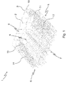
- a dishwasher rack according to the invention is generally designated with 1 (with a shape suitable for being housed in the upper part of the washing tank of a dishwashing machine), which comprises the usual structure 2 made in a manner known per se of metal wires 3 that firstly are bent or shaped in different manners and then welded together to form the assembly, in order to support objects.
- the rack 1 has a substantially parallelepiped shape with a bottom 4 with walls extending along the edges thereof, a pair of side walls 5 and 6, a front wall 7 and a rear wall 8 opposing each other respectively; then at the top the rack is opened such to allow it to be loaded from the top as usual.
- tip-up shelves 10, 11, 12, 13, and 14 are provided along the side walls 5 and 6 of the rack; such shelves have different dimensions one with respect to the other but they can be advantageously all mounted according to the same system and therefore reference will be made below only to one of them: however what is described applies also to the other ones.
- the shelf 10 is advantageously made of plastic material and it comprises a mainly opened structure such to facilitate the water flow, it having a base 15 for being mounted to the wall of the rack from which a wide-mesh reticular frame 16 extends.
- Such frame advantageously comprises a central mesh for supporting objects such as cups and a plurality ofperimetral housings for supporting objects such as stem glasses.
- two pairs of appendices 18 and 19 extend symmetrically with respect to a central axis of the shelf, arranged vertically with reference to figure 6 .
- the shelves 10, 11, 12, 13 and 14 are mounted on the side walls 5 and 6 of the rack by means of respective supports 20.
- the latter also made preferably of plastic material, are all equal to one another, and are fastened to the rack walls by means of rear snap-on projections 21, 22, which are configured such to be engaged with the horizontal wires 51, 52 of the side wall 5 of the rack 1.
- the supports 20 are removable with respect to the rack 1, such that the user can remove them if he/she does not desire to use the shelves or if he/she desires to clean the supports 20; but once they are fastened to the rack 1 and in operation, they substantially remain still with respect to the rack 1, since the width of the projections 21, 22 is slightly lower than the distance between two vertical consecutive wires 53 in the side wall 5 or 6.
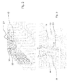
- the supports 20 In the front the supports 20 have a central groove 24 interposed between two walls 25 having an irregular saw-tooth profile.
- the walls 25 act for supporting a pair of supporting pins 28 for the shelf 10, arranged at the sides of the spigot 17.
- the shelf 10 comprises, preferably as one piece, a retaining pin 77 applied on the surface thereof faced towards the relevant support 20, and suitable for allowing the shelf 10 to be firmly vertically positioned.
- Such retaining pin 77 co-operates to this end with the guiding groove 24 or with another suitable locking element integral with the support 20.
- the tip-up shelves 10 can be positioned with different angles with respect to the corresponding side wall 5, 6 of the rack 1 and, contemporaneously, even at different heights from the bottom thereof.
- each shelf 10 is slidably guided in the guiding groove 24 of the relevant support 20, with respect thereto it can be positioned at different heights due to the saw-tooth profile of the walls 25.
- the shelf By engaging the supporting pins 28 of a shelf 10 with the teeth of the walls 25 as shown in figure 3 , the shelf can rotate with respect to these teeth that therefore act as a seat for the rotation of the pins.
- the ends 18a of the appendices 18 are shaped in a concave manner combined with the vertical metal wires of the side walls 5,6 of the rack, as it is better shown in figures 3 and 5 ; the distance between the appendices 18 is preferably equal to or a multiple of the distance between vertical wires 53, such to guarantee appendices 18 to engage therewith, with the supports 20 in any positions.
- the shelf 10 is angled at about 60° with respect to the corresponding wall 5,6 of the rack.
- the appendices 19 abut against this horizontal wire.
- the shaped end 19a of the appendices acts as a surface for the abutment against the rack wire and since the appendices 19 are longer than those 18, the latter do not interfere with the positioning of the shelf, which therefore takes an angle different than the previous case (about 45°).
- any other angles of the shelves can be obtained in racks such as that shown in the figures, wherein the side walls 5,6 have a step-like arrangement, that is with parallel flat portions, allowing the supports 20 to be positioned at different distances from the wires of the structure.
- the shelves 10 can also be completely tilted such to lean against the side walls 5,6 of the rack.
- the shelf 10 comprises, at the central area of the frame 16, a hook (seen in Fig. 2 ) protruding from the upper face of the frame 16, such that, when the shelf is in the vertical position, this hook engages the central groove 24 of the support 20.
- the hook has an appropriate elasticity allowing it to be inserted in the groove 24 and to remain locked therein, thus forcing the shelf 10 to remain in the vertical position.
- the hook can comprise a head composed of two elastic tabs symmetric one another.
- the tip-up shelves 10 are adjustable not only with reference to the angle with respect to the corresponding side wall of the rack 1 upon which they are mounted, but also their position can be height-adjusted with respect to the bottom of the rack 1, without the need of removing them from the wall.
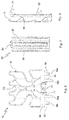
- a first variant is shown in figures 9 and 10 ; for the sake of brevity the following disclosure highlights only the parts of this variant different than the main embodiment described above; for the same reason, when possible, the same reference numerals will be used with one or more prime symbols for denoting structurally and functionally equivalent elements.
- a tip-up shelf 10' is connectable with the support 20' by means of the same means already described in the previous embodiment; this shelf 10' is provided with a base 15', which in turn comprises at least two snap-on projections 18' compatible with the vertical wires 53 of the rack 1.
- the distance between the snap-on projections 18' is equal to an integer multiple of the distance between the vertical wires 53.
- said shelf 10' comprises one or more appendices 19' having a polygonal, preferably triangular, and more preferably isosceles triangle cross-section, with the height parallel to the axis of symmetry of the shelf 10'.
- the appendices 19' are compatible with the saw-tooth profiles of the walls 25, and are advantageously strengthened for unloading on the support 20' a part of the weight resting on the shelf 10', thus avoiding a part of the weight to be unloaded from the inside to the outside of the rack 1 acting on the horizontal wire 51,52.
- the isosceles triangle cross-section of the appendices 19', by interfering with the saw-tooth profiles of the walls 25, allows the shelf 10' to reach stable angles equivalent to those of the main embodiment described above.
- cam constraint walls 19a' each of which penetrating into an appendix 19'; these walls 19a' interfere with the walls 25 when to the shelf 10' a rotary movement about its axis of symmetry is given, thus constraining the travel thereof and in addition avoiding the possibility of breaking the engagement spigot 17.
- a second variant is the one shown in fig. 11 , which is different than the first variant described above for the provision of a shelf 10" with dimensions about twice those of the variant described above; this shelf 10" comprises a base 15", that in turn comprises at least four snap-on projections 18" joined in pairs by a crossbar 18b".
- the base 15' has a length about twice that of the first variant.
- This variant comprises appendices 19" structurally and functionally equivalent to the appendices 19' of the first variant; such appendices abut against a support 20". Moreover, this variant advantageously makes it possible to wash bigger dishes in a position raised with respect to the bottom 4 of the rack 1, such as conservation containers or the like.
- a third variant is shown in fig.12 .
- This variant is different than the first one described above, since it provides at least one retaining hook 23"' positioned on the top of a support 20'" and at the top end of a longitudinal groove 24"'.
- the retaining hook 23'" comprises a pair of elastic tabs 23a"', parallel each other and vertically oriented; these tabs 23a"' give the retaining hook 23 a double function, that is the retaining and the guiding one.
- the retaining function is exerted by the hook 23'" when a frame 16"', structurally and functionally equivalent to the frame 16, is coupled to the support 20"' by the longitudinal groove 24"'; when a force from the bottom to the top with a modulus less than a certain threshold is exerted, the tabs 23a'" put up resistance to a spigot 17"' structurally and functionally equivalent to the spigot 17 of the main embodiment while, when the modulus of said force is higher than said threshold value, the tabs 23a"' open, letting the spigot 17"' to be separated from the longitudinal groove 24"'.
- the guiding function is exerted by the hook 23"' when a frame 16"', structurally and functionally equivalent to the frame 16 of the main embodiment, is separated from the support 20"'; in this situation the tabs 23a'" guide the spigot 17"' into the groove 24"', and they open without a particular resistance.
- the tabs 23a"' generate a striker facilitating the positioning of the tip-up shelf in the raised position.
- a further variant is given by a shelf similar to shelves 10, 10', 10" just described, wherein said shelf is supported by more than one support 20, 20', 20", 20"', such to allow a higher load to be positioned on said shelf with respect to the variants described above.
Landscapes
- Washing And Drying Of Tableware (AREA)
Claims (13)
- Gestell (10, 10', 10") für einen Geschirrspülerkorb (1), wobei der Geschirrspülerkorb (1) eine Struktur (2) mit einem Boden (4) aufweist, von dem aus sich eine Mehrzahl von Wänden (5, 6, 7, 8) erstrecken, wobei zumindest das Gestell (10, 10', 10") mit einer der Wände verbunden werden kann, um allgemein Objekte zu halten, wobei der Korb zumindest eine Halterung (20, 20', 20", 20'") umfasst, die an der Wand (5, 6, 7, 8) angeordnet ist, entlang derer das Gestell in unterschiedlichen Höhen vom Boden (4) positioniert werden kann, wobei die Halterung (20, 20', 20", 20'") eine Führungsnut (24, 24'") zum Führen des Gestells (10, 10', 10") umfasst, und wobei zwei Wände (25) ein Sägezahnprofil auf ge-genüberliegenden Seiten der Nut aufweisen,
dadurch gekennzeichnet, dass
das Gestell (10, 10', 10") einen Zapfen (17, 17'") und ein Paar von Halterungspins (28), die an Seiten des Zapfens (17, 17'") angeordnet sind, umfasst, wobei der Zapfen (17, 17'") ausgebildet ist, verschiebbar in der Führungsnut (24) geführt zu werden, und wobei die Wände (25) der Halterung (20, 20', 20", 20'") angepasst sind, zum Halten des Paares von Halterungspins (28) in unterschiedlichen Höhen vom Boden (4) zu wirken. - Gestell (10, 10', 10") nach Anspruch 1, dadurch gekennzeichnet, dass sie eine Befestigungsbasis (15), von der aus sich eine Mehrzahl von Fortsätzen (18, 18', 18", 19, 19', 19") transversal erstrecken, und einen im Wesentlichen rechteckigen Rahmen (16, 16'") an der gegenüberliegenden Seite umfasst.
- Gestell (10, 10', 10") nach Anspruch 2, wobei die Fortsätze (18, 18', 18", 19, 19', 19") symmetrisch in Paaren ausgebildet sind in Bezug auf eine Längsachse des Gestells, wobei dort ein Befestigungszapfen (17, 17'") vorgesehen ist.
- Gestell (10, 10', 10") nach Anspruch 2 oder 3, wobei die Enden der Fortsätze (18, 19) so geformt sind, dass sie konkave, angeschrägte oder ähnliche Oberflächen beinhalten.
- Gestell (10, 10', 10") nach einem der Ansprüche 2 bis 4, wobei die Fortsätze (19', 19") gegen die Halterung (20, 20', 20", 20'") anliegen.
- Gestellhalterung (20, 20', 20", 20"') für einen Geschirrspülerkorb (1), wobei der Geschirrspülerkorb (1) eine Struktur (2) mit einem Boden (4) aufweist, von dem aus sich eine Mehrzahl von Wänden (5, 6, 7, 8) erstrecken, wobei zumindest ein Gestell (10, 10', 10") mit einer der Wände verbunden werden kann, um allgemein Objekte zu halten, wobei der Korb zumindest eine Halterung (20, 20', 20", 20'") umfasst, die an die Wand (5, 6, 7, 8) angeordnet ist, entlang derer das Gestell in unterschiedlichen Höhen vom Boden (4) positioniert werden kann,
dadurch gekennzeichnet, dass
die Halterung (20, 20', 20", 20'") eine Führungsnut (24, 24'") zum Führen des Gestells (10, 10', 10") umfasst, und wobei zwei Wände (25) ein Sägezahnprofil an gegenüberliegenden Seiten der Nut aufweisen, wobei das Gestell (10, 10', 10") einen Zapfen (17, 17'") und ein Paar von Halterungspins (28), die an Seiten des Zapfens (17, 17'") angeordnet sind, umfasst, und wobei der Zapfen (17, 17'") ausgebildet ist, verschiebbar in der Führungsnut (24) geführt zu werden, und wobei die Wände (25) der Halterung (20, 20', 20", 20'") ausgebildet sind, zum Halten des Paars von Halterungspins (28) in unterschiedlichen Höhen vom Boden (4) zu wirken. - Halterung (20, 20', 20", 20'") nach Anspruch 6, umfassend Reiter (23a'"), die als Schließbügel wirken, um das Positionieren des Gestells in einer oberen Position zu erleichtern.
- Geschirrspülerkorb (1), umfassend ein Gestell (10, 10', 10") nach einem der Ansprüche 1 bis 5 und eine Gestellhalterung (20, 20', 20", 20'") nach Anspruch 6 oder 7, wobei der Geschirrspülerkorb (1) eine Struktur (2) mit einem Boden (4) umfasst, von dem aus sich eine Mehrzahl von Wänden (5, 6, 7, 8) erstrecken, wobei das Gestell (10, 10', 10") mit einer der Wände verbunden werden kann, um allgemein Objekte zu halten, wobei die Halterung (20, 20', 20", 20'") an der Wand (5, 6, 7, 8) angeordnet werden kann, entlang derer das Gestell in unterschiedlichen Höhen vom Boden (4) positioniert werden kann.
- Korb (1) nach Anspruch 8, wobei das Gestell (10, 10', 10") an der Halterung in unterschiedlichen Winkeln relativ zu der entsprechenden Wand (5, 6, 7, 8) befestigt werden kann.
- Korb (1) nach Anspruch 8 oder 9, wobei das Gestell (10) Fortsätze (18, 18', 18", 19) umfasst, die gegen die Wand (5, 6, 7, 8) anliegen, um das Gestell in einem vorbestimmten Winkel relativ zu der Wand zu halten.
- Korb (1) nach Anspruch 10, dessen Struktur (2) zumindest teilweise aus Metalldrähten (3) oder dergleichen gemacht ist, gegen welche die Fortsätze (18, 18', 18", 19) des Gestells (10) anliegen, um die unterschiedlichen Winkel relativ zu der Wand (5, 6, 7, 8), an der es befestigt ist, zu bestimmen.
- Korb (1) nach Anspruch 11, wobei die Enden (18a, 19a) der Fortsätze (18, 19) so geformt sind, dass sie konkave, angeschrägte oder ähnliche Oberflächen beinhalten, um so den Kontakt mit den Drähten (3) der Korbstruktur zu verbessern.
- Korb (1) nach einem der Ansprüche 8 bis 12, wobei die zumindest eine Halterung (20, 20', 20", 20'") lösbar an einer Wand (5, 6, 7, 8) gesichert ist.
Applications Claiming Priority (1)
| Application Number | Priority Date | Filing Date | Title |
|---|---|---|---|
| IT000739A ITTO20110739A1 (it) | 2011-08-05 | 2011-08-05 | Cestello per lavastoviglie con mensola per il supporto di oggetti |
Publications (2)
| Publication Number | Publication Date |
|---|---|
| EP2554094A1 EP2554094A1 (de) | 2013-02-06 |
| EP2554094B1 true EP2554094B1 (de) | 2016-10-19 |
Family
ID=44899176
Family Applications (1)
| Application Number | Title | Priority Date | Filing Date |
|---|---|---|---|
| EP12179131.3A Active EP2554094B1 (de) | 2011-08-05 | 2012-08-03 | Korb für Geschirrspülmaschine mit Gestell zur Halterung von Gegenständen |
Country Status (3)
| Country | Link |
|---|---|
| EP (1) | EP2554094B1 (de) |
| IT (1) | ITTO20110739A1 (de) |
| PL (1) | PL2554094T3 (de) |
Families Citing this family (4)
| Publication number | Priority date | Publication date | Assignee | Title |
|---|---|---|---|---|
| ITMI20130295A1 (it) * | 2013-02-28 | 2014-08-29 | Candy Spa | Cestello per lavastoviglie. |
| US9770103B2 (en) | 2014-06-30 | 2017-09-26 | Hewlett Packard Enterprise Development Lp | Shelf movable between an extended shelf position and a shelf storage position |
| CN106963319B (zh) * | 2016-01-13 | 2019-10-11 | 青岛海尔洗碗机有限公司 | 一种洗碗机搁架 |
| DE102018214019A1 (de) * | 2018-08-20 | 2020-02-20 | BSH Hausgeräte GmbH | Glashalteraufsatz |
Family Cites Families (4)
| Publication number | Priority date | Publication date | Assignee | Title |
|---|---|---|---|---|
| DE10347765A1 (de) * | 2003-10-14 | 2005-05-12 | Bsh Bosch Siemens Hausgeraete | Geschirrkorb mit höhenverstellbaren Ablagen |
| US20070039904A1 (en) * | 2005-08-18 | 2007-02-22 | Electrolux Home Products, Inc. | Brackets for supporting article holders |
| ITRN20080010A1 (it) * | 2008-02-26 | 2009-08-27 | Indesit Co Spa | Cestello per lavastoviglie e lavastoviglie comprendente il cestello. |
| DE102009002270A1 (de) * | 2009-04-07 | 2010-10-14 | BSH Bosch und Siemens Hausgeräte GmbH | Geschirrspülmaschine |
-
2011
- 2011-08-05 IT IT000739A patent/ITTO20110739A1/it unknown
-
2012
- 2012-08-03 EP EP12179131.3A patent/EP2554094B1/de active Active
- 2012-08-03 PL PL12179131T patent/PL2554094T3/pl unknown
Non-Patent Citations (1)
| Title |
|---|
| None * |
Also Published As
| Publication number | Publication date |
|---|---|
| PL2554094T3 (pl) | 2017-09-29 |
| ITTO20110739A1 (it) | 2013-02-06 |
| EP2554094A1 (de) | 2013-02-06 |
Similar Documents
| Publication | Publication Date | Title |
|---|---|---|
| US20100155280A1 (en) | Cutlery tray for a dishwasher | |
| US8757419B2 (en) | Crockery basket comprising height-adjustable racks | |
| KR101310264B1 (ko) | 식기세척기의 랙 | |
| KR102001912B1 (ko) | 식기세척기 | |
| US8042559B2 (en) | Dishwasher having rack with shelf holder | |
| US20070039904A1 (en) | Brackets for supporting article holders | |
| EP1275336A1 (de) | Geschirrkorb mit kippbaren Gestellen mit ausziehbarem Besteckgitter | |
| EP2554094B1 (de) | Korb für Geschirrspülmaschine mit Gestell zur Halterung von Gegenständen | |
| KR20110092320A (ko) | 컵 지지부를 갖춘 식기세척기 바스켓 | |
| EP3188643B1 (de) | Geschirrspülerdrahtgestell mit verbesserter trägeradapterzinkenanordnungsstruktur | |
| WO2016000791A1 (en) | A dishwasher wire rack having an improved carrier adaptor structure | |
| EP2594186A1 (de) | Ausziehbare Besteckablage für Spülmaschine | |
| CN109662676B (zh) | 洗碗机的活动排、碗篮组件和洗碗机 | |
| WO2006016759A1 (en) | Spoon basket structure of dish washer | |
| EP2554096B1 (de) | Korb für Geschirrspülmaschinen mit schwenkbare Stützelemente und zumindest einem abnehmbaren Halteelement | |
| EP1413241B1 (de) | Geschirrspüler mit oberem Geschirrkorb teilweise untergebracht in einer Einbuchtung in der Tür und ausgerüstet mit einem frontalen kippbaren Gestell | |
| CN209884089U (zh) | 一种洗碗机的搁架以及洗碗机 | |
| CN208693222U (zh) | 一种洗碗机的上碗篮组件 | |
| KR20090024004A (ko) | 식기 세척기 | |
| EP2554100B1 (de) | Geschirrkorb für Geschirrspülmaschine mit Gestell, das mit einem Deckel versehen ist | |
| JP4123367B2 (ja) | 食器洗浄機の食器かご | |
| KR20080044080A (ko) | 식기세척기의 랙 어셈블리 | |
| KR20220061653A (ko) | 식기건조대 | |
| CN221469809U (zh) | 用于洗碗机的支撑组件及洗碗机 | |
| JP4724515B2 (ja) | 水切りかご |
Legal Events
| Date | Code | Title | Description |
|---|---|---|---|
| PUAI | Public reference made under article 153(3) epc to a published international application that has entered the european phase |
Free format text: ORIGINAL CODE: 0009012 |
|
| AK | Designated contracting states |
Kind code of ref document: A1 Designated state(s): AL AT BE BG CH CY CZ DE DK EE ES FI FR GB GR HR HU IE IS IT LI LT LU LV MC MK MT NL NO PL PT RO RS SE SI SK SM TR |
|
| AX | Request for extension of the european patent |
Extension state: BA ME |
|
| 17P | Request for examination filed |
Effective date: 20130806 |
|
| RBV | Designated contracting states (corrected) |
Designated state(s): AL AT BE BG CH CY CZ DE DK EE ES FI FR GB GR HR HU IE IS IT LI LT LU LV MC MK MT NL NO PL PT RO RS SE SI SK SM TR |
|
| 17Q | First examination report despatched |
Effective date: 20141112 |
|
| GRAP | Despatch of communication of intention to grant a patent |
Free format text: ORIGINAL CODE: EPIDOSNIGR1 |
|
| INTG | Intention to grant announced |
Effective date: 20160704 |
|
| GRAS | Grant fee paid |
Free format text: ORIGINAL CODE: EPIDOSNIGR3 |
|
| GRAA | (expected) grant |
Free format text: ORIGINAL CODE: 0009210 |
|
| AK | Designated contracting states |
Kind code of ref document: B1 Designated state(s): AL AT BE BG CH CY CZ DE DK EE ES FI FR GB GR HR HU IE IS IT LI LT LU LV MC MK MT NL NO PL PT RO RS SE SI SK SM TR |
|
| REG | Reference to a national code |
Ref country code: GB Ref legal event code: FG4D |
|
| REG | Reference to a national code |
Ref country code: CH Ref legal event code: EP |
|
| REG | Reference to a national code |
Ref country code: AT Ref legal event code: REF Ref document number: 837605 Country of ref document: AT Kind code of ref document: T Effective date: 20161115 |
|
| REG | Reference to a national code |
Ref country code: IE Ref legal event code: FG4D |
|
| REG | Reference to a national code |
Ref country code: DE Ref legal event code: R096 Ref document number: 602012024259 Country of ref document: DE |
|
| RAP2 | Party data changed (patent owner data changed or rights of a patent transferred) |
Owner name: WHIRLPOOL EMEA S.P.A |
|
| REG | Reference to a national code |
Ref country code: NL Ref legal event code: MP Effective date: 20161019 |
|
| REG | Reference to a national code |
Ref country code: LT Ref legal event code: MG4D |
|
| PG25 | Lapsed in a contracting state [announced via postgrant information from national office to epo] |
Ref country code: LV Free format text: LAPSE BECAUSE OF FAILURE TO SUBMIT A TRANSLATION OF THE DESCRIPTION OR TO PAY THE FEE WITHIN THE PRESCRIBED TIME-LIMIT Effective date: 20161019 |
|
| REG | Reference to a national code |
Ref country code: AT Ref legal event code: MK05 Ref document number: 837605 Country of ref document: AT Kind code of ref document: T Effective date: 20161019 |
|
| PG25 | Lapsed in a contracting state [announced via postgrant information from national office to epo] |
Ref country code: NO Free format text: LAPSE BECAUSE OF FAILURE TO SUBMIT A TRANSLATION OF THE DESCRIPTION OR TO PAY THE FEE WITHIN THE PRESCRIBED TIME-LIMIT Effective date: 20170119 Ref country code: GR Free format text: LAPSE BECAUSE OF FAILURE TO SUBMIT A TRANSLATION OF THE DESCRIPTION OR TO PAY THE FEE WITHIN THE PRESCRIBED TIME-LIMIT Effective date: 20170120 Ref country code: LT Free format text: LAPSE BECAUSE OF FAILURE TO SUBMIT A TRANSLATION OF THE DESCRIPTION OR TO PAY THE FEE WITHIN THE PRESCRIBED TIME-LIMIT Effective date: 20161019 Ref country code: SE Free format text: LAPSE BECAUSE OF FAILURE TO SUBMIT A TRANSLATION OF THE DESCRIPTION OR TO PAY THE FEE WITHIN THE PRESCRIBED TIME-LIMIT Effective date: 20161019 |
|
| PG25 | Lapsed in a contracting state [announced via postgrant information from national office to epo] |
Ref country code: PT Free format text: LAPSE BECAUSE OF FAILURE TO SUBMIT A TRANSLATION OF THE DESCRIPTION OR TO PAY THE FEE WITHIN THE PRESCRIBED TIME-LIMIT Effective date: 20170220 Ref country code: RS Free format text: LAPSE BECAUSE OF FAILURE TO SUBMIT A TRANSLATION OF THE DESCRIPTION OR TO PAY THE FEE WITHIN THE PRESCRIBED TIME-LIMIT Effective date: 20161019 Ref country code: NL Free format text: LAPSE BECAUSE OF FAILURE TO SUBMIT A TRANSLATION OF THE DESCRIPTION OR TO PAY THE FEE WITHIN THE PRESCRIBED TIME-LIMIT Effective date: 20161019 Ref country code: AT Free format text: LAPSE BECAUSE OF FAILURE TO SUBMIT A TRANSLATION OF THE DESCRIPTION OR TO PAY THE FEE WITHIN THE PRESCRIBED TIME-LIMIT Effective date: 20161019 Ref country code: IS Free format text: LAPSE BECAUSE OF FAILURE TO SUBMIT A TRANSLATION OF THE DESCRIPTION OR TO PAY THE FEE WITHIN THE PRESCRIBED TIME-LIMIT Effective date: 20170219 Ref country code: BE Free format text: LAPSE BECAUSE OF FAILURE TO SUBMIT A TRANSLATION OF THE DESCRIPTION OR TO PAY THE FEE WITHIN THE PRESCRIBED TIME-LIMIT Effective date: 20161019 Ref country code: ES Free format text: LAPSE BECAUSE OF FAILURE TO SUBMIT A TRANSLATION OF THE DESCRIPTION OR TO PAY THE FEE WITHIN THE PRESCRIBED TIME-LIMIT Effective date: 20161019 Ref country code: HR Free format text: LAPSE BECAUSE OF FAILURE TO SUBMIT A TRANSLATION OF THE DESCRIPTION OR TO PAY THE FEE WITHIN THE PRESCRIBED TIME-LIMIT Effective date: 20161019 Ref country code: FI Free format text: LAPSE BECAUSE OF FAILURE TO SUBMIT A TRANSLATION OF THE DESCRIPTION OR TO PAY THE FEE WITHIN THE PRESCRIBED TIME-LIMIT Effective date: 20161019 |
|
| REG | Reference to a national code |
Ref country code: FR Ref legal event code: PLFP Year of fee payment: 6 |
|
| REG | Reference to a national code |
Ref country code: DE Ref legal event code: R097 Ref document number: 602012024259 Country of ref document: DE |
|
| PG25 | Lapsed in a contracting state [announced via postgrant information from national office to epo] |
Ref country code: SK Free format text: LAPSE BECAUSE OF FAILURE TO SUBMIT A TRANSLATION OF THE DESCRIPTION OR TO PAY THE FEE WITHIN THE PRESCRIBED TIME-LIMIT Effective date: 20161019 Ref country code: CZ Free format text: LAPSE BECAUSE OF FAILURE TO SUBMIT A TRANSLATION OF THE DESCRIPTION OR TO PAY THE FEE WITHIN THE PRESCRIBED TIME-LIMIT Effective date: 20161019 Ref country code: EE Free format text: LAPSE BECAUSE OF FAILURE TO SUBMIT A TRANSLATION OF THE DESCRIPTION OR TO PAY THE FEE WITHIN THE PRESCRIBED TIME-LIMIT Effective date: 20161019 Ref country code: DK Free format text: LAPSE BECAUSE OF FAILURE TO SUBMIT A TRANSLATION OF THE DESCRIPTION OR TO PAY THE FEE WITHIN THE PRESCRIBED TIME-LIMIT Effective date: 20161019 Ref country code: RO Free format text: LAPSE BECAUSE OF FAILURE TO SUBMIT A TRANSLATION OF THE DESCRIPTION OR TO PAY THE FEE WITHIN THE PRESCRIBED TIME-LIMIT Effective date: 20161019 |
|
| PLBE | No opposition filed within time limit |
Free format text: ORIGINAL CODE: 0009261 |
|
| STAA | Information on the status of an ep patent application or granted ep patent |
Free format text: STATUS: NO OPPOSITION FILED WITHIN TIME LIMIT |
|
| PG25 | Lapsed in a contracting state [announced via postgrant information from national office to epo] |
Ref country code: SM Free format text: LAPSE BECAUSE OF FAILURE TO SUBMIT A TRANSLATION OF THE DESCRIPTION OR TO PAY THE FEE WITHIN THE PRESCRIBED TIME-LIMIT Effective date: 20161019 Ref country code: BG Free format text: LAPSE BECAUSE OF FAILURE TO SUBMIT A TRANSLATION OF THE DESCRIPTION OR TO PAY THE FEE WITHIN THE PRESCRIBED TIME-LIMIT Effective date: 20170119 |
|
| 26N | No opposition filed |
Effective date: 20170720 |
|
| PG25 | Lapsed in a contracting state [announced via postgrant information from national office to epo] |
Ref country code: SI Free format text: LAPSE BECAUSE OF FAILURE TO SUBMIT A TRANSLATION OF THE DESCRIPTION OR TO PAY THE FEE WITHIN THE PRESCRIBED TIME-LIMIT Effective date: 20161019 |
|
| REG | Reference to a national code |
Ref country code: CH Ref legal event code: PL |
|
| PG25 | Lapsed in a contracting state [announced via postgrant information from national office to epo] |
Ref country code: MC Free format text: LAPSE BECAUSE OF FAILURE TO SUBMIT A TRANSLATION OF THE DESCRIPTION OR TO PAY THE FEE WITHIN THE PRESCRIBED TIME-LIMIT Effective date: 20161019 |
|
| GBPC | Gb: european patent ceased through non-payment of renewal fee |
Effective date: 20170803 |
|
| PG25 | Lapsed in a contracting state [announced via postgrant information from national office to epo] |
Ref country code: LI Free format text: LAPSE BECAUSE OF NON-PAYMENT OF DUE FEES Effective date: 20170831 Ref country code: CH Free format text: LAPSE BECAUSE OF NON-PAYMENT OF DUE FEES Effective date: 20170831 |
|
| REG | Reference to a national code |
Ref country code: IE Ref legal event code: MM4A |
|
| REG | Reference to a national code |
Ref country code: FR Ref legal event code: PLFP Year of fee payment: 7 |
|
| PG25 | Lapsed in a contracting state [announced via postgrant information from national office to epo] |
Ref country code: LU Free format text: LAPSE BECAUSE OF NON-PAYMENT OF DUE FEES Effective date: 20170803 |
|
| PG25 | Lapsed in a contracting state [announced via postgrant information from national office to epo] |
Ref country code: GB Free format text: LAPSE BECAUSE OF NON-PAYMENT OF DUE FEES Effective date: 20170803 Ref country code: IE Free format text: LAPSE BECAUSE OF NON-PAYMENT OF DUE FEES Effective date: 20170803 |
|
| PGFP | Annual fee paid to national office [announced via postgrant information from national office to epo] |
Ref country code: PL Payment date: 20180605 Year of fee payment: 7 |
|
| PG25 | Lapsed in a contracting state [announced via postgrant information from national office to epo] |
Ref country code: MT Free format text: LAPSE BECAUSE OF NON-PAYMENT OF DUE FEES Effective date: 20170803 |
|
| PG25 | Lapsed in a contracting state [announced via postgrant information from national office to epo] |
Ref country code: HU Free format text: LAPSE BECAUSE OF FAILURE TO SUBMIT A TRANSLATION OF THE DESCRIPTION OR TO PAY THE FEE WITHIN THE PRESCRIBED TIME-LIMIT; INVALID AB INITIO Effective date: 20120803 |
|
| PG25 | Lapsed in a contracting state [announced via postgrant information from national office to epo] |
Ref country code: CY Free format text: LAPSE BECAUSE OF NON-PAYMENT OF DUE FEES Effective date: 20161019 |
|
| PG25 | Lapsed in a contracting state [announced via postgrant information from national office to epo] |
Ref country code: MK Free format text: LAPSE BECAUSE OF FAILURE TO SUBMIT A TRANSLATION OF THE DESCRIPTION OR TO PAY THE FEE WITHIN THE PRESCRIBED TIME-LIMIT Effective date: 20161019 |
|
| PG25 | Lapsed in a contracting state [announced via postgrant information from national office to epo] |
Ref country code: TR Free format text: LAPSE BECAUSE OF FAILURE TO SUBMIT A TRANSLATION OF THE DESCRIPTION OR TO PAY THE FEE WITHIN THE PRESCRIBED TIME-LIMIT Effective date: 20161019 |
|
| PG25 | Lapsed in a contracting state [announced via postgrant information from national office to epo] |
Ref country code: AL Free format text: LAPSE BECAUSE OF FAILURE TO SUBMIT A TRANSLATION OF THE DESCRIPTION OR TO PAY THE FEE WITHIN THE PRESCRIBED TIME-LIMIT Effective date: 20161019 |
|
| PG25 | Lapsed in a contracting state [announced via postgrant information from national office to epo] |
Ref country code: PL Free format text: LAPSE BECAUSE OF NON-PAYMENT OF DUE FEES Effective date: 20190803 |
|
| P01 | Opt-out of the competence of the unified patent court (upc) registered |
Effective date: 20230523 |
|
| REG | Reference to a national code |
Ref country code: DE Ref legal event code: R081 Ref document number: 602012024259 Country of ref document: DE Owner name: WHIRLPOOL EMEA S.R.L., IT Free format text: FORMER OWNER: INDESIT COMPANY S.P.A., FABRIANO, ANCONA, IT |
|
| PGFP | Annual fee paid to national office [announced via postgrant information from national office to epo] |
Ref country code: DE Payment date: 20250827 Year of fee payment: 14 |
|
| PGFP | Annual fee paid to national office [announced via postgrant information from national office to epo] |
Ref country code: IT Payment date: 20250710 Year of fee payment: 14 |
|
| PGFP | Annual fee paid to national office [announced via postgrant information from national office to epo] |
Ref country code: FR Payment date: 20250825 Year of fee payment: 14 |