EP2554233A1 - Wabenstrukturfilter - Google Patents
Wabenstrukturfilter Download PDFInfo
- Publication number
- EP2554233A1 EP2554233A1 EP11765667A EP11765667A EP2554233A1 EP 2554233 A1 EP2554233 A1 EP 2554233A1 EP 11765667 A EP11765667 A EP 11765667A EP 11765667 A EP11765667 A EP 11765667A EP 2554233 A1 EP2554233 A1 EP 2554233A1
- Authority
- EP
- European Patent Office
- Prior art keywords
- cells
- honeycomb filter
- trapping layer
- additional
- deposition
- Prior art date
- Legal status (The legal status is an assumption and is not a legal conclusion. Google has not performed a legal analysis and makes no representation as to the accuracy of the status listed.)
- Withdrawn
Links
Images



Classifications
-
- B—PERFORMING OPERATIONS; TRANSPORTING
- B01—PHYSICAL OR CHEMICAL PROCESSES OR APPARATUS IN GENERAL
- B01J—CHEMICAL OR PHYSICAL PROCESSES, e.g. CATALYSIS OR COLLOID CHEMISTRY; THEIR RELEVANT APPARATUS
- B01J35/00—Catalysts, in general, characterised by their form or physical properties
- B01J35/50—Catalysts, in general, characterised by their form or physical properties characterised by their shape or configuration
- B01J35/56—Foraminous structures having flow-through passages or channels, e.g. grids or three-dimensional [3D] monoliths
-
- B—PERFORMING OPERATIONS; TRANSPORTING
- B01—PHYSICAL OR CHEMICAL PROCESSES OR APPARATUS IN GENERAL
- B01D—SEPARATION
- B01D53/00—Separation of gases or vapours; Recovering vapours of volatile solvents from gases; Chemical or biological purification of waste gases, e.g. engine exhaust gases, smoke, fumes, flue gases, aerosols
- B01D53/34—Chemical or biological purification of waste gases
- B01D53/92—Chemical or biological purification of waste gases of engine exhaust gases
- B01D53/94—Chemical or biological purification of waste gases of engine exhaust gases by catalytic processes
- B01D53/9445—Simultaneously removing carbon monoxide, hydrocarbons or nitrogen oxides making use of three-way catalysts [TWC] or four-way-catalysts [FWC]
-
- B—PERFORMING OPERATIONS; TRANSPORTING
- B01—PHYSICAL OR CHEMICAL PROCESSES OR APPARATUS IN GENERAL
- B01D—SEPARATION
- B01D46/00—Filters or filtering processes specially modified for separating dispersed particles from gases or vapours
- B01D46/24—Particle separators, e.g. dust precipitators, using rigid hollow filter bodies
- B01D46/2403—Particle separators, e.g. dust precipitators, using rigid hollow filter bodies characterised by the physical shape or structure of the filtering element
- B01D46/2418—Honeycomb filters
-
- B—PERFORMING OPERATIONS; TRANSPORTING
- B01—PHYSICAL OR CHEMICAL PROCESSES OR APPARATUS IN GENERAL
- B01J—CHEMICAL OR PHYSICAL PROCESSES, e.g. CATALYSIS OR COLLOID CHEMISTRY; THEIR RELEVANT APPARATUS
- B01J23/00—Catalysts comprising metals or metal oxides or hydroxides, not provided for in group B01J21/00
- B01J23/16—Catalysts comprising metals or metal oxides or hydroxides, not provided for in group B01J21/00 of arsenic, antimony, bismuth, vanadium, niobium, tantalum, polonium, chromium, molybdenum, tungsten, manganese, technetium or rhenium
- B01J23/32—Manganese, technetium or rhenium
- B01J23/34—Manganese
-
- B—PERFORMING OPERATIONS; TRANSPORTING
- B01—PHYSICAL OR CHEMICAL PROCESSES OR APPARATUS IN GENERAL
- B01J—CHEMICAL OR PHYSICAL PROCESSES, e.g. CATALYSIS OR COLLOID CHEMISTRY; THEIR RELEVANT APPARATUS
- B01J23/00—Catalysts comprising metals or metal oxides or hydroxides, not provided for in group B01J21/00
- B01J23/38—Catalysts comprising metals or metal oxides or hydroxides, not provided for in group B01J21/00 of noble metals
- B01J23/54—Catalysts comprising metals or metal oxides or hydroxides, not provided for in group B01J21/00 of noble metals combined with metals, oxides or hydroxides provided for in groups B01J23/02 - B01J23/36
- B01J23/56—Platinum group metals
- B01J23/63—Platinum group metals with rare earths or actinides
-
- B—PERFORMING OPERATIONS; TRANSPORTING
- B01—PHYSICAL OR CHEMICAL PROCESSES OR APPARATUS IN GENERAL
- B01J—CHEMICAL OR PHYSICAL PROCESSES, e.g. CATALYSIS OR COLLOID CHEMISTRY; THEIR RELEVANT APPARATUS
- B01J37/00—Processes, in general, for preparing catalysts; Processes, in general, for activation of catalysts
- B01J37/02—Impregnation, coating or precipitation
- B01J37/03—Precipitation; Co-precipitation
- B01J37/038—Precipitation; Co-precipitation to form slurries or suspensions, e.g. a washcoat
-
- C—CHEMISTRY; METALLURGY
- C04—CEMENTS; CONCRETE; ARTIFICIAL STONE; CERAMICS; REFRACTORIES
- C04B—LIME, MAGNESIA; SLAG; CEMENTS; COMPOSITIONS THEREOF, e.g. MORTARS, CONCRETE OR LIKE BUILDING MATERIALS; ARTIFICIAL STONE; CERAMICS; REFRACTORIES; TREATMENT OF NATURAL STONE
- C04B38/00—Porous mortars, concrete, artificial stone or ceramic ware; Preparation thereof
- C04B38/0006—Honeycomb structures
- C04B38/0009—Honeycomb structures characterised by features relating to the cell walls, e.g. wall thickness or distribution of pores in the walls
-
- C—CHEMISTRY; METALLURGY
- C04—CEMENTS; CONCRETE; ARTIFICIAL STONE; CERAMICS; REFRACTORIES
- C04B—LIME, MAGNESIA; SLAG; CEMENTS; COMPOSITIONS THEREOF, e.g. MORTARS, CONCRETE OR LIKE BUILDING MATERIALS; ARTIFICIAL STONE; CERAMICS; REFRACTORIES; TREATMENT OF NATURAL STONE
- C04B38/00—Porous mortars, concrete, artificial stone or ceramic ware; Preparation thereof
- C04B38/0006—Honeycomb structures
- C04B38/0016—Honeycomb structures assembled from subunits
-
- F—MECHANICAL ENGINEERING; LIGHTING; HEATING; WEAPONS; BLASTING
- F01—MACHINES OR ENGINES IN GENERAL; ENGINE PLANTS IN GENERAL; STEAM ENGINES
- F01N—GAS-FLOW SILENCERS OR EXHAUST APPARATUS FOR MACHINES OR ENGINES IN GENERAL; GAS-FLOW SILENCERS OR EXHAUST APPARATUS FOR INTERNAL-COMBUSTION ENGINES
- F01N3/00—Exhaust or silencing apparatus having means for purifying, rendering innocuous, or otherwise treating exhaust
- F01N3/02—Exhaust or silencing apparatus having means for purifying, rendering innocuous, or otherwise treating exhaust for cooling, or for removing solid constituents of, exhaust
- F01N3/021—Exhaust or silencing apparatus having means for purifying, rendering innocuous, or otherwise treating exhaust for cooling, or for removing solid constituents of, exhaust by means of filters
- F01N3/022—Exhaust or silencing apparatus having means for purifying, rendering innocuous, or otherwise treating exhaust for cooling, or for removing solid constituents of, exhaust by means of filters characterised by specially adapted filtering structure, e.g. honeycomb, mesh or fibrous
- F01N3/0222—Exhaust or silencing apparatus having means for purifying, rendering innocuous, or otherwise treating exhaust for cooling, or for removing solid constituents of, exhaust by means of filters characterised by specially adapted filtering structure, e.g. honeycomb, mesh or fibrous the structure being monolithic, e.g. honeycombs
-
- B—PERFORMING OPERATIONS; TRANSPORTING
- B01—PHYSICAL OR CHEMICAL PROCESSES OR APPARATUS IN GENERAL
- B01D—SEPARATION
- B01D2255/00—Catalysts
- B01D2255/10—Noble metals or compounds thereof
- B01D2255/102—Platinum group metals
- B01D2255/1021—Platinum
-
- B—PERFORMING OPERATIONS; TRANSPORTING
- B01—PHYSICAL OR CHEMICAL PROCESSES OR APPARATUS IN GENERAL
- B01D—SEPARATION
- B01D2255/00—Catalysts
- B01D2255/10—Noble metals or compounds thereof
- B01D2255/102—Platinum group metals
- B01D2255/1023—Palladium
-
- B—PERFORMING OPERATIONS; TRANSPORTING
- B01—PHYSICAL OR CHEMICAL PROCESSES OR APPARATUS IN GENERAL
- B01D—SEPARATION
- B01D2255/00—Catalysts
- B01D2255/10—Noble metals or compounds thereof
- B01D2255/104—Silver
-
- B—PERFORMING OPERATIONS; TRANSPORTING
- B01—PHYSICAL OR CHEMICAL PROCESSES OR APPARATUS IN GENERAL
- B01D—SEPARATION
- B01D2255/00—Catalysts
- B01D2255/10—Noble metals or compounds thereof
- B01D2255/106—Gold
-
- B—PERFORMING OPERATIONS; TRANSPORTING
- B01—PHYSICAL OR CHEMICAL PROCESSES OR APPARATUS IN GENERAL
- B01D—SEPARATION
- B01D2255/00—Catalysts
- B01D2255/20—Metals or compounds thereof
- B01D2255/206—Rare earth metals
-
- B—PERFORMING OPERATIONS; TRANSPORTING
- B01—PHYSICAL OR CHEMICAL PROCESSES OR APPARATUS IN GENERAL
- B01D—SEPARATION
- B01D2255/00—Catalysts
- B01D2255/20—Metals or compounds thereof
- B01D2255/207—Transition metals
-
- B—PERFORMING OPERATIONS; TRANSPORTING
- B01—PHYSICAL OR CHEMICAL PROCESSES OR APPARATUS IN GENERAL
- B01D—SEPARATION
- B01D2255/00—Catalysts
- B01D2255/90—Physical characteristics of catalysts
- B01D2255/91—NOx-storage component incorporated in the catalyst
-
- B—PERFORMING OPERATIONS; TRANSPORTING
- B01—PHYSICAL OR CHEMICAL PROCESSES OR APPARATUS IN GENERAL
- B01D—SEPARATION
- B01D2255/00—Catalysts
- B01D2255/90—Physical characteristics of catalysts
- B01D2255/912—HC-storage component incorporated in the catalyst
-
- B—PERFORMING OPERATIONS; TRANSPORTING
- B01—PHYSICAL OR CHEMICAL PROCESSES OR APPARATUS IN GENERAL
- B01D—SEPARATION
- B01D2255/00—Catalysts
- B01D2255/90—Physical characteristics of catalysts
- B01D2255/92—Dimensions
- B01D2255/9202—Linear dimensions
-
- B—PERFORMING OPERATIONS; TRANSPORTING
- B01—PHYSICAL OR CHEMICAL PROCESSES OR APPARATUS IN GENERAL
- B01D—SEPARATION
- B01D2255/00—Catalysts
- B01D2255/90—Physical characteristics of catalysts
- B01D2255/92—Dimensions
- B01D2255/9205—Porosity
-
- B—PERFORMING OPERATIONS; TRANSPORTING
- B01—PHYSICAL OR CHEMICAL PROCESSES OR APPARATUS IN GENERAL
- B01J—CHEMICAL OR PHYSICAL PROCESSES, e.g. CATALYSIS OR COLLOID CHEMISTRY; THEIR RELEVANT APPARATUS
- B01J23/00—Catalysts comprising metals or metal oxides or hydroxides, not provided for in group B01J21/00
-
- C—CHEMISTRY; METALLURGY
- C04—CEMENTS; CONCRETE; ARTIFICIAL STONE; CERAMICS; REFRACTORIES
- C04B—LIME, MAGNESIA; SLAG; CEMENTS; COMPOSITIONS THEREOF, e.g. MORTARS, CONCRETE OR LIKE BUILDING MATERIALS; ARTIFICIAL STONE; CERAMICS; REFRACTORIES; TREATMENT OF NATURAL STONE
- C04B2111/00—Mortars, concrete or artificial stone or mixtures to prepare them, characterised by specific function, property or use
- C04B2111/00474—Uses not provided for elsewhere in C04B2111/00
- C04B2111/00793—Uses not provided for elsewhere in C04B2111/00 as filters or diaphragms
-
- F—MECHANICAL ENGINEERING; LIGHTING; HEATING; WEAPONS; BLASTING
- F01—MACHINES OR ENGINES IN GENERAL; ENGINE PLANTS IN GENERAL; STEAM ENGINES
- F01N—GAS-FLOW SILENCERS OR EXHAUST APPARATUS FOR MACHINES OR ENGINES IN GENERAL; GAS-FLOW SILENCERS OR EXHAUST APPARATUS FOR INTERNAL-COMBUSTION ENGINES
- F01N2330/00—Structure of catalyst support or particle filter
- F01N2330/06—Ceramic, e.g. monoliths
-
- F—MECHANICAL ENGINEERING; LIGHTING; HEATING; WEAPONS; BLASTING
- F01—MACHINES OR ENGINES IN GENERAL; ENGINE PLANTS IN GENERAL; STEAM ENGINES
- F01N—GAS-FLOW SILENCERS OR EXHAUST APPARATUS FOR MACHINES OR ENGINES IN GENERAL; GAS-FLOW SILENCERS OR EXHAUST APPARATUS FOR INTERNAL-COMBUSTION ENGINES
- F01N2330/00—Structure of catalyst support or particle filter
- F01N2330/60—Discontinuous, uneven properties of filter material, e.g. different material thickness along the longitudinal direction; Higher filter capacity upstream than downstream in same housing
-
- F—MECHANICAL ENGINEERING; LIGHTING; HEATING; WEAPONS; BLASTING
- F01—MACHINES OR ENGINES IN GENERAL; ENGINE PLANTS IN GENERAL; STEAM ENGINES
- F01N—GAS-FLOW SILENCERS OR EXHAUST APPARATUS FOR MACHINES OR ENGINES IN GENERAL; GAS-FLOW SILENCERS OR EXHAUST APPARATUS FOR INTERNAL-COMBUSTION ENGINES
- F01N2510/00—Surface coverings
- F01N2510/06—Surface coverings for exhaust purification, e.g. catalytic reaction
- F01N2510/068—Surface coverings for exhaust purification, e.g. catalytic reaction characterised by the distribution of the catalytic coatings
- F01N2510/0682—Surface coverings for exhaust purification, e.g. catalytic reaction characterised by the distribution of the catalytic coatings having a discontinuous, uneven or partially overlapping coating of catalytic material, e.g. higher amount of material upstream than downstream or vice versa
-
- F—MECHANICAL ENGINEERING; LIGHTING; HEATING; WEAPONS; BLASTING
- F01—MACHINES OR ENGINES IN GENERAL; ENGINE PLANTS IN GENERAL; STEAM ENGINES
- F01N—GAS-FLOW SILENCERS OR EXHAUST APPARATUS FOR MACHINES OR ENGINES IN GENERAL; GAS-FLOW SILENCERS OR EXHAUST APPARATUS FOR INTERNAL-COMBUSTION ENGINES
- F01N3/00—Exhaust or silencing apparatus having means for purifying, rendering innocuous, or otherwise treating exhaust
- F01N3/02—Exhaust or silencing apparatus having means for purifying, rendering innocuous, or otherwise treating exhaust for cooling, or for removing solid constituents of, exhaust
- F01N3/021—Exhaust or silencing apparatus having means for purifying, rendering innocuous, or otherwise treating exhaust for cooling, or for removing solid constituents of, exhaust by means of filters
- F01N3/033—Exhaust or silencing apparatus having means for purifying, rendering innocuous, or otherwise treating exhaust for cooling, or for removing solid constituents of, exhaust by means of filters in combination with other devices
- F01N3/035—Exhaust or silencing apparatus having means for purifying, rendering innocuous, or otherwise treating exhaust for cooling, or for removing solid constituents of, exhaust by means of filters in combination with other devices with catalytic reactors
-
- Y—GENERAL TAGGING OF NEW TECHNOLOGICAL DEVELOPMENTS; GENERAL TAGGING OF CROSS-SECTIONAL TECHNOLOGIES SPANNING OVER SEVERAL SECTIONS OF THE IPC; TECHNICAL SUBJECTS COVERED BY FORMER USPC CROSS-REFERENCE ART COLLECTIONS [XRACs] AND DIGESTS
- Y02—TECHNOLOGIES OR APPLICATIONS FOR MITIGATION OR ADAPTATION AGAINST CLIMATE CHANGE
- Y02T—CLIMATE CHANGE MITIGATION TECHNOLOGIES RELATED TO TRANSPORTATION
- Y02T10/00—Road transport of goods or passengers
- Y02T10/10—Internal combustion engine [ICE] based vehicles
- Y02T10/12—Improving ICE efficiencies
Definitions
- the present invention relates to a honeycomb filter.
- One proposed honeycomb filter includes a porous partition portion, in which a cell that is open at one end and closed at the other end and a cell that is closed at one end and open at the other end are alternately disposed, and a layer that is formed on the partition portion and traps and removes particulate matter (PM) contained in an exhaust gas (see, for example, Patent Documents 1 to 3).
- This honeycomb filter can trap PM using the trapping layer with low pressure loss.
- regeneration treatment in which trapped PM is burnt to restore the function of the filter may be performed.
- a trapping layer disposed on each of partition portions could decrease pressure loss, the formation of the trapping layer alone had no significant influence on the regeneration treatment efficiency.
- regeneration treatment for example, the amount of fuel in an engine is increased to raise the temperature.
- the present invention has employed the following means.
- a honeycomb filter includes a plurality of porous partition portions each forming a cell, the cell being open at one end and closed at the other end and serving as a flow path of a fluid, and a trapping layer for trapping and removing solid components contained in the fluid, the trapping layer being disposed on each of the partition portions, wherein, when a visualization test is performed after a predetermined crack inspection shows that the honeycomb filter has no cracks, the visualization test feeding fine particles having an average particle size determined from the average pore size of the partition portions from one end face of the honeycomb filter at a gauge pressure of 1 Pa or more and 10 Pa or less and irradiating the other end face with light to visualize fine particles flowing from that other end face, the cells include additional-deposition cells having a luminance difference of 150 cd/m 2 or more in the visualization test, and the ratio R (%) of the number of the additional-deposition cells to the total number of cells satisfying 0(%) ⁇ R ⁇ 20 (%).
- a honeycomb filter includes a plurality of porous partition portions each forming a cell, the cell being open at one end and closed at the other end and serving as a flow path of a fluid, and a trapping layer for trapping and removing solid components contained in the fluid, the trapping layer being disposed on each of the partition portions, wherein the cells include additional-deposition cells each having an additional-deposition region for further trapping the solid components after the solid components are trapped, and the ratio R (%) of the number of the additional-deposition cells to the total number of cells satisfies 0 (%) ⁇ R ⁇ 20 (%).
- the honeycomb filter has the trapping layer on each of the partition portions forming the cells.
- the cells include additional-deposition cells having a predetermined luminance difference in a visualization test.
- the additional-deposition cells are formed such that the ratio R (%) of the additional-deposition cells to the total number of cells satisfies 0 (%) ⁇ R ⁇ 20 (%).
- the regeneration rate tends to increase with the amount of trapped solid components.
- a large amount of solid components are deposited on the additional-deposition cells, and the combustion of the solid components on the additional-deposition cells in regeneration treatment serves as an ignition point and facilitates removal of trapped solid components.
- the honeycomb filter has at least one additional-deposition cell, and the ratio R of the number of additional-deposition cells to the total number of cells is 20 (%) or less. A ratio R of 20 (%) or less results in an effective decrease in pressure loss and more efficient removal of trapped solid components.
- the "additional-deposition cells” may be cells on which an additional amount of solid components can be trapped after solid components have been trapped as compared with the other general cells, or cells on which a 10% by weight or more larger amount of solid components than at least one of adjacent cells can be deposited.
- the term "crack”, as used herein, refers to a narrow space having such a size that affects PM trap and disposed in a partition portion between a cell having an opening on at least the inlet side through which a fluid flows into the cell (hereinafter also referred to as an inlet cell) and a cell having an opening on at least the outlet side through which a fluid flows out of the cell (hereinafter also referred to as an outlet cell) in the axial direction of a carrier passing through the inlet cell and the outlet cell or along a cross section perpendicular to the axial direction.
- the trapping layer may be formed on an inlet cell and the additional-deposition cells may be among the inlet cells for the fluid.
- the additional-deposition cells may be cells on which an additional amount of solid components can be trapped after solid components have been trapped as compared with the other cells.
- the ratio R of the additional-deposition cells to the total number of cells is preferably 7 (%) or less. This allows trapped solid components to be more efficiently removed with decreased pressure loss.
- the additional-deposition cells are cells having an incomplete trapping layer or cells having no trapping layer or both.
- Such additional-deposition cells have lower flow path resistance than cells having a complete trapping layer and therefore allow a larger amount of fluid to pass through than the other cells, thus trapping a larger amount of solid components.
- the additional-deposition cells can be relatively easily prepared by forming an incomplete trapping layer.
- the "cell having an incomplete trapping layer” may be a cell having a trapping layer having a smaller thickness than the trapping layer in the other portion.
- the trapping layer having a smaller thickness may have a thickness of 30% or less, more preferably 50% or less, of the average thickness of the trapping layers over the entire honeycomb filter.
- the "cell having an incomplete trapping layer” may have a trapping layer having substantially the same thickness as in the other portion but have a portion having no trapping layer in at least part of the cell.
- the portion having no trapping layer may be disposed in any position with respect to the fluid flow direction and may have a maximum length of 300 ⁇ m or less, more preferably 200 ⁇ m or less.
- the trapping layer of each additional-deposition cell may constitute 75% or less, 50% or less, or 25% or less of the area of the entire inner wall of one cell.
- the additional-deposition cells preferably have no trapping layer. This can further decrease flow path resistance and allows an increased amount of solid components to be trapped.
- the trapping layers may be formed by supplying an inorganic material that is a raw material for the trapping layers to the cells using a gas as a transport medium. Transportation using a gas can be utilized to relatively easily control the morphology, such as the thickness, of the trapping layer.
- the additional-deposition cells may be identified by pressure-feeding fine particles from one end face of the honeycomb filter and irradiating the other end face with light to visualize fine particles flowing from that other end face.
- the additional-deposition cells can be identified by a relatively easy method for illuminating fine particles flowing from the end face.
- the identification method may involve feeding fine particles having a known particle size distribution and a known concentration from one end face of the honeycomb filter in a darkroom, irradiating the other end face with a slit-like laser beam, and detecting a luminance difference resulting from fine particles leaking from that other end face.
- Examples of the "fine particles" fed from the end face include fine particles generated by the combustion of incense, such as an incense stick, fine particles generated by spray or vaporization of a solvent, such as water, and fine particles generated by spreading fine particles, such as calcium carbonate fine particles.
- the fine particles have an average particle size determined from the average pore size of the partition portions and are selected according to the permeability of the partition portions. For example, the fine particles may have an average particle size of 0.3 ⁇ m or more and 10 ⁇ m or less.
- the conditions for pressure feed include a gauge pressure of 1 Pa or more and 10 Pa or less.
- the additional-deposition cells have a luminance difference of 150 cd/m 2 or more from the lowest luminance of the cells.
- the partition portions may contain one or more inorganic materials selected from cordierite, SiC, mullite, aluminum titanate, alumina, silicon nitride, SIALON, zirconium phosphate, zirconia, titania, and silica.
- the trapping layers may contain one or more inorganic materials selected from cordierite, SiC, mullite, aluminum titanate, alumina, silicon nitride, SIALON, zirconium phosphate, zirconia, titania, and silica.
- the trapping layers are formed of the material of the partition portions.
- a honeycomb filter according to an aspect of the present invention may be formed by joining two or more honeycomb segments with a bonding layer.
- Each of the honeycomb segments has the partition portion and the trapping layer. Joining with the bonding layer can increase the mechanical strength of the honeycomb filter.
- At least one of the partition portion and the trapping layer may be loaded with a catalyst.
- the catalyst can facilitate the removal of components contained in a fluid, such as the removal of trapped solid components by combustion.
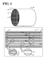
- Fig. 1 is a schematic explanatory view of the structure of a honeycomb filter 20 according to an embodiment of the present invention.
- Fig. 2 is an explanatory view of a method for calculating the thickness of a trapping layer on the basis of SEM observation.
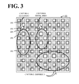
- Fig. 3 is an explanatory view of an outer area, the central area, and dispersed additional-deposition cells 25.
- Fig. 4 is an explanatory view of a laser smoke detector 60.
- Fig. 5 is a schematic view of PM trap on additional-deposition cells 25.
- Fig. 6 is an explanatory view of a temperature change caused by an additional-deposition cell 25 in regeneration treatment. As illustrated in Fig.
- the honeycomb filter 20 includes two or more honeycomb segments 21 joined together with a bonding layer 27 and an outer protective portion 28 disposed around the honeycomb segments 21.
- Each of the honeycomb segments 21 includes a partition portion 22.
- the honeycomb filter 20 includes porous partition portions 22 each forming a cell 23, the cell 23 being open at one end and sealed with a sealing portion 26 at the other end and serving as an exhaust gas flow path, and a trapping layer 24 for trapping and removing solid components (hereinafter also referred to as PM) contained in a fluid, the trapping layer being disposed on each of the partition portions 22.
- the honeycomb filter 20 is cylindrical, each of the honeycomb segments 21 is rectangular columnar, and each of the cells 23 is rectangular.
- the partition portion 22 is formed such that a cell 23 that is open at one end and closed at the other end and a cell 23 that is closed at one end and open at the other end are alternately disposed.
- an exhaust gas enters a cell 23 having an opening on the inlet side (hereinafter also referred to as an inlet cell), passes through the trapping layer 24 and the partition portion 22, and is exhausted from another cell 23 having an opening on the outlet side (hereinafter also referred to as an outlet cell), during which PM in the exhaust gas is trapped on the trapping layer 24.
- the honeycomb filter 20 may have any external shape and may be cylindrical, quadrangular prismatic, cylindroid, or hexagonal columnar.
- the honeycomb segments 21 may have any external shape, preferably have a plane that is easy to join, and may have a square columnar (quadrangular prismatic, hexagonal columnar, or the like) with a polygonal cross section.
- the cross section of the cells may be polygonal, such as triangular, tetragonal, hexagonal, or octagonal, circular, or streamlined, such as elliptical, or combination thereof.
- the cells 23 may have a tetragonal cross section perpendicular to the exhaust gas flow direction.
- the honeycomb filter 20 preferably has a cell pitch of 1.0 mm or more and 2.5 mm or less.
- the pressure loss during PM deposition decreases with increasing filtration area.
- the initial pressure loss increases with decreasing cell diameter.
- the cell pitch, the cell density, and the thickness of the partition portion 22 may be determined in consideration of trade-offs between initial pressure loss, pressure loss during PM deposition, and PM trapping efficiency.
- the partition portion 22 is porous and may contain one or more inorganic materials selected from cordierite, Si-bonded SiC, recrystallized SiC, aluminum titanate, mullite, silicon nitride, SIALON, zirconium phosphate, zirconia, titania, alumina, and silica. Among these, cordierite, Si-bonded SiC, and recrystallized SiC are preferred.
- the partition portion 22 preferably has a porosity of 30% by volume or more and 85% by volume or less, more preferably 35% by volume or more and 65% by volume or less. The porosity is measured by a mercury intrusion method.
- the partition portion 22 preferably has an average pore size of 10 ⁇ m or more and 60 ⁇ m or less.
- the average pore size is measured by a mercury intrusion method.
- the partition portion 22 preferably has a thickness of 150 ⁇ m or more and 600 ⁇ m or less, more preferably 200 ⁇ m or more and 400 ⁇ m or less. A thickness of 150 ⁇ m or more results in high mechanical strength, and a thickness of 600 ⁇ m or less results in low pressure loss.
- the partition portion 22 having such a porosity, an average pore size, and a thickness allows an exhaust gas to easily pass through the partition portion 22 and PM to be easily trapped and removed.
- the trapping layer 24 for trapping and removing PM contained in an exhaust gas may be formed of particle groups having an average particle size smaller than the average pore size of the partition portion 22 and may be disposed on the partition portion 22.
- the trapping layer 24 preferably has an average pore size of 0.2 ⁇ m or more and 10 ⁇ m or less and a porosity of 40% by volume or more and 95% by volume or less.
- An average pore size of 0.2 ⁇ m or more results in the prevention of an excessive initial pressure loss in the absence of PM deposition.
- An average pore size of 10 ⁇ m or less results in an improvement in trapping efficiency, the prevention of PM entering the pores of the partition portion 22 through the trapping layer 24, and the prevention of the reduction in the effect of decreasing pressure loss during PM deposition.
- a porosity of 40% by volume or more results in the prevention of an excessive initial pressure loss in the absence of PM deposition.
- a porosity of 95% by volume or less results in the formation of a surface layer serving as a durable trapping layer 24.
- the average size of particles constituting the trapping layer is preferably 0.5 ⁇ m or more and 15 ⁇ m or less. When the average size of particles constituting the trapping layer is 0.5 ⁇ m or more, a space between the particles constituting the trapping layer can be sufficiently provided, thus ensuring high permeability of the trapping layer and preventing a sudden increase in pressure loss.
- the trapping layer 24 preferably has an average thickness of 10 ⁇ m or more and 80 ⁇ m or less. At a trapping layer thickness of 10 ⁇ m or more, it is easy to trap PM. A trapping layer thickness of 80 ⁇ m or less results in a decrease in the permeation resistance of a partition and a decrease in pressure loss.
- the average thickness of the trapping layer is preferably 20 ⁇ m or more and 60 ⁇ m or less, more preferably 30 ⁇ m or more and 50 ⁇ m or less.
- the trapping layer 24 may be formed on the partition portion 22 of each of the exhaust gas inlet and outlet cells. As illustrated in Fig. 1 , preferably, the trapping layer 24 is formed on the partition portion 22 of each inlet cell and is not formed on the partition portion 22 of each outlet cell. This allows PM contained in a fluid to be efficiently removed with further decreased pressure loss. Furthermore, this facilitates the manufacture of the honeycomb filter 20.
- the trapping layer 24 may contain one or more inorganic materials selected from cordierite, SiC, mullite, aluminum titanate, alumina, silicon nitride, SIALON, zirconium phosphate, zirconia, titania, and silica.
- the trapping layer 24 is formed of the material of the partition portion 22. More preferably, the trapping layer 24 contains 70% by weight or more ceramic or metallic inorganic fiber. The fiber facilitates PM trapping.
- the inorganic fiber of the trapping layer 24 may contain one or more materials selected from aluminosilicate, alumina, silica, zirconia, ceria, and mullite.
- the average particle size of the particle groups constituting the trapping layer 24 is a mean value measured by observing the trapping layer 24 with a scanning electron microscope (SEM) and measuring the individual particles of the trapping layer 24 in an image obtained.
- the average particle size of raw material particles is the median size (D50) measured with a laser diffraction/scattering particle size distribution analyzer using water as a dispersion medium.
- the thickness of the trapping layer 24 in other words, the thickness of the particle groups constituting the trapping layer is determined in the following manner.
- the thickness of the trapping layer is determined by embedding a partition substrate of the honeycomb filter 20 in a resin and polishing the resin to prepare a sample for observation, observing the sample with a scanning electron microscope (SEM), and analyzing an image obtained.
- SEM scanning electron microscope
- the sample for observation is prepared by cutting and polishing such that a cross section perpendicular to the fluid flow direction serves as an observation surface.
- the observation surface of the sample for observation prepared is photographed at measuring points described below in a visual field of approximately 500 ⁇ m x 500 ⁇ m at a SEM magnification in the range of 100 to 500.
- the outermost contour of a partition is then hypothetically drawn on an image obtained.
- the outermost contour of a partition is a line showing the outline of the partition and refers to a projector obtained by irradiating a partition surface (a surface to be irradiated; see the top in Fig. 2 ) with hypothetical parallel light in the direction perpendicular to the partition surface (see the middle in Fig. 2 ).
- the outermost contour of a partition is composed of line segments corresponding to a plurality of top surfaces of the partition at different levels irradiated with hypothetical light and perpendicular lines each connecting line segments corresponding to adjacent top surfaces of the partition at different levels.
- the line segments corresponding to the top surfaces of the partition are drawn at "5% resolution", in which, for example, asperities having a length of 5 ⁇ m or less are disregarded with respect to a line segment having a length of 100 ⁇ m. This prevents the occurrence of too many line segments in the horizontal direction.
- the presence of a trapping layer is disregarded.
- the outermost contour of the particle groups constituting a trapping layer is hypothetically drawn.
- the outermost contour of the particle groups is a line showing the outline of the trapping layer and refers to a projector obtained by irradiating a trapping layer surface (a surface to be irradiated; see the top in Fig. 2 ) with hypothetical parallel light in the direction perpendicular to the trapping layer surface (see the middle in Fig. 2 ).
- the outermost contour of the particle groups is composed of line segments corresponding to a plurality of top surfaces of the particle groups at different levels irradiated with hypothetical light and perpendicular lines each connecting line segments corresponding to adjacent top surfaces of the particle groups at different levels.
- the line segments corresponding to the top surfaces of the particle groups are drawn, for example, at the same "resolution" as in the partition.
- For a porous trapping layer in a sample for observation prepared by embedding in a resin and polishing, some particle groups are observed as if they floated in the air.
- the outermost contour is therefore drawn with the projector obtained by hypothetical light irradiation.
- the standard reference line of the partition is determined on the basis of the levels and lengths of the line segments of the outermost contour corresponding to the top surfaces of the partition thus drawn.
- the standard reference line is the average line of the outermost contour of the partition (see the bottom in Fig. 2 ).
- the average level of the particle groups is determined on the basis of the levels and lengths of the line segments of the outermost contour corresponding to the top surfaces of the particle groups thus drawn.
- the average level of the particle groups is the average line of the outermost contour of the particle groups (see the bottom in Fig. 2 ).
- the difference (length) between the average level of the particle groups and the standard reference line of the partition is considered to be the thickness of the trapping layer (the thickness of the particle groups) in the image.
- the thickness of a trapping layer can be determined.
- the thicknesses of a trapping layer measured at a plurality of points of measurement may be averaged to determine the average thickness of the trapping layer.
- the average pore size and the porosity of the trapping layer 24 are determined by image analysis based on SEM observation. In the same manner as in the thickness of the trapping layer, as illustrated in Fig. 2 , images of a cross section of the honeycomb filter 20 are obtained with SEM. A region between the outermost contour of a partition and the outermost contour of particle groups is considered to be a region occupied by a trapping layer (a trapping layer region). In the trapping layer region, a region including the particle groups is referred to as a "particle group region", and a region including no particle group is referred to as a "pore region of the trapping layer". The area of the trapping layer region (trapping layer area) and the area of the particle group region (particle group area) are determined.
- the porosity of the trapping layer is calculated by dividing the particle group area by the trapping layer area and multiplying the quotient by 100.
- pore region of the trapping layer an incircle inscribed in the outermost contours of the particle groups and the partition and the periphery of the particle groups is drawn such that the diameter of the incircle is as large as possible.
- a plurality of incircles can be drawn in one "pore region of the trapping layer"
- a plurality of incircles as large as possible are drawn such that the pore region is sufficiently filled with the incircles.
- the average diameter of the incircles is considered to be the average pore size of the trapping layer. In this manner, the average pore size and the porosity of the trapping layer 24 can be determined.
- a honeycomb filter 20 includes the additional-deposition cells 25 each having an additional-deposition region for trapping more PM than a region having a complete trapping layer after solid components have been trapped.
- the additional-deposition cells 25 may be any cells on which additional PM can be deposited, for example, cells having an incomplete trapping layer 24, cells having no trapping layer 24, or both.
- An incomplete trapping layer 24 has decreased flow path resistance and allows an increased amount of exhaust gas to flow through, resulting in an increased amount of trapped PM, as compared with a complete trapping layer 24.
- an additional-deposition cell 25 having an incomplete trapping layer 24 may be a cell having a trapping layer having a thickness smaller than the average thickness in the other portion.
- the trapping layer having a smaller thickness may have an average thickness of 30% or less, more preferably 50% or less, of the average thickness of the trapping layers over the entire honeycomb filter.
- the additional-deposition cell 25 having an incomplete trapping layer 24 may have a trapping layer having substantially the same thickness as in the other portion but have a portion having no trapping layer in at least part of the cell.
- the portion having no trapping layer may be disposed in any position with respect to exhaust gas flow direction and may have a maximum length of 300 ⁇ m or less, more preferably 200 ⁇ m or less.
- the trapping layer 24 may constitute 75% or less, 50% or less, or 25% or less of the area of the entire inner wall of one cell 23.
- An additional-deposition cell having no trapping layer on the partition portion is more preferred.
- a portion having no trapping layer 24 is preferred because the portion has lower flow path resistance and traps a larger amount of solid components than a portion having the trapping layer 24.
- the trapping layer 24 may be formed on at least inlet cells, and the additional-deposition cells 25 may be inlet cells.
- the ratio R (%) of the number of the additional-deposition cells 25 to the total number of cells satisfies 0 (%) ⁇ R ⁇ 20 (%).
- the ratio R is preferably 7 (%) or less. When the ratio R is more than 0% and 20% or less, this can further increase regeneration efficiency and prevent an increase in pressure loss. As illustrated in Fig.
- the additional-deposition cells 25 may be present in an outer area or the central area of the honeycomb segments 21 or may be dispersed.
- the additional-deposition cells 25 may be present in an outer area or the central area of the honeycomb filter 20 or may be dispersed.
- the additional-deposition cells 25 are preferably present in an outer area of the honeycomb segments 21.
- "outer-area cells” and "central-area cells” when a cross section perpendicular to the flow paths of the segments or the honeycomb filter is divided into an outer region and a central region such that the outer region has the same area as the central region, a cell in the outer region may be an outer-area cell, and a cell in the central region may be a central-area cell.
- the additional-deposition cells 25 satisfy the relationship of R1 > R2 > R3, wherein R1 denotes the flow path resistance of a completely coated cell 23a in which a trapping layer 24 is formed on the entire inner surface of the cell, R2 denotes the flow path resistance of an additional-deposition cell 25a in which a trapping layer 24 is partially formed on the inner surface of the cell, and R3 denotes the flow path resistance of an additional-deposition cell 25b in which no trapping layer 24 is formed on the cell 23.
- the order of exhaust gas flow rates Q1, Q2, and Q3 are Q1 ⁇ Q2 ⁇ Q3, wherein Q1, Q2, and Q3 denote the exhaust gas flow rates at which the exhaust gas flows through the completely coated cell 23a and the additional-deposition cells 25a and 25b, respectively.
- the flow rate of an exhaust gas passing through the partition portion 22 increases as the area of the trapping layer 24 decreases. It is conceivable that the amount of PM per unit volume is substantially constant and a higher exhaust gas flow rate results in a larger amount of PM deposition.
- the order of the amounts of PM deposition M1, M2, and M3 is M1 ⁇ M2 ⁇ M3, wherein M1, M2, and M3 denote the amounts of PM deposition on the partition portions 22 in the completely coated cells 23a and the additional-deposition cells 25a and 25b, respectively.
- M1, M2, and M3 denote the amounts of PM deposition on the partition portions 22 in the completely coated cells 23a and the additional-deposition cells 25a and 25b, respectively.
- the amount of PM deposition increases as the area of the trapping layer 24 decreases (see the middle in Fig. 6 ).
- regeneration treatment to remove PM deposit by combustion results in a further increased temperature in an additional-deposition cell 25 immediately after the regeneration treatment because of PM combustion.
- the increased temperature of the additional-deposition cell 25 affects adjacent cells 23, promoting temperature rise in the entire honeycomb filter 20 (see the bottom in Fig. 6 ). This facilitates the regeneration treatment of PM.
- An additional-deposition cell 25 can be identified by relative luminance in a laser smoke test, as illustrated in Fig. 4 .
- the laser smoke test involves the pressure feed of fine particles (smoke) generated by the combustion of incense from one end face of a honeycomb filter and irradiation of the other end face with light for visualization of fine particles flowing from that other end face.
- a cell having an incomplete trapping layer 24 has lower permeation resistance of the partition portion 22 than the other cells, allowing more fine particles to flowing out from an end face. While the end face is irradiated with light, light luminance depends on the number of fine particles. Thus, the number of fine particles can be estimated from light luminance.
- the laser smoke detector 60 includes an installation base 63, which houses an incense stick stand 62 to which an incense stick 61 is fixed and fixes a honeycomb filter 20, a pressurization mechanism 64 for pressurizing the interior space of the installation base 63, a photoirradiation apparatus 65 for irradiating smoke emitted from the top surface of the honeycomb filter 20 with a plane light, a photographic apparatus 66 for taking a picture of light-reflecting smoke on top of the honeycomb filter 20, and a hood 67 on which the photoirradiation apparatus 65 and the photographic apparatus 66 are disposed.
- the top surface of the installation base 63 has a feed opening 63a for supplying smoke to the honeycomb filter 20.
- the laser smoke detector 60 includes a fine particle source that preferably produces fine particles, for example, having a particle size in the range of approximately 0.3 to 10 ⁇ m. More specifically, the fine particle source may be the combustion of incense, such as an incense stick, spray or vaporization of a solvent, such as water, and spreading of fine particles, such as calcium carbonate fine particles, and is preferably an incense stick.
- the pressurization mechanism 64 may be a booster pump.
- the photoirradiation apparatus 65 is preferably an apparatus that can emit directional light having a wavelength that induces diffuse reflection by fine particles, for example, a laser, such as a semiconductor laser, a dye laser, or a free electron laser.
- the photographic apparatus 66 may be any apparatus that can take a picture of fine particles of smoke irradiated with light, for example, an optical camera, or a digital camera or a digital video camera each having CCD or CMOS. Further details of the apparatus structures and test conditions can be found in Japanese Patent No. 3904933 and Japanese Unexamined Patent Application Publication No. 2009-258090 . The procedure for the laser smoke test will be described below. First, a partition portion 22 of a honeycomb filter 20 to be tested is examined for a crack by another test method.
- a CT scan may be used to detect a crack.
- the term "crack”, as used herein, refers to a narrow space having such a size that affects PM trap and disposed in a partition portion between an inlet cell and an outlet cell in the axial direction of a carrier passing through the inlet cell and the outlet cell or along a cross section perpendicular to the axial direction.
- the incense stick 61 is ignited and fixed to the incense stick stand 62 in the installation base 63.
- One end face of the honeycomb filter 20 is placed on the feed opening 63a such that the cells 23 of the honeycomb filter 20 are disposed on the feed opening 63a.
- the honeycomb filter 20 is disposed on a seal (not shown) so as to prevent the leakage of smoke from the space between the honeycomb filter 20 and the installation base 63.
- the hood 67 is fixed to a test position such that light from the photoirradiation apparatus 65 is disposed in the vicinity of (for example, 3 to 5 mm above) one end face of the honeycomb filter 20. At this test position, the hood 67 surrounds the honeycomb filter 20 and prevents the agitation of fine particle of smoke emitted from the end face of the honeycomb filter 20. Subsequently, smoke of the incense stick 61 is supplied to the cells 23 of the honeycomb filter 20 with the pressurization mechanism 64.
- Fine particles of the smoke emitted from the other end face are irradiated with light emitted from the photoirradiation apparatus 65, and reflected light is captured with the photographic apparatus 66.
- a region brighter than the other region is considered to be a region of an additional-deposition cell 25.
- the fine particles In the laser smoke test (visualization test), the fine particles have an average particle size determined from the average pore size of the partition portions and are selected according to the permeability of the partition portions.
- fine particles are supplied at a gauge pressure of 1 Pa or more and 10 Pa or less.
- a cell having a relative luminance difference of 150 cd/m 2 or more is considered to be an additional-deposition cell.
- a method for forming the trapping layer 24 may involve supplying a gas containing the raw material for the trapping layer to an inlet cell using a gas (air) as a transport medium for the raw material for the trapping layer. This is preferred because the particle groups constituting the trapping layer become coarse and can form a trapping layer having a very high porosity.
- the raw material for the trapping layer may be inorganic fiber or inorganic particles.
- the inorganic fiber may be that described above and preferably has an average particle size of 0.5 ⁇ m or more and 8 ⁇ m or less and an average length of 100 ⁇ m or more and 500 ⁇ m or less.
- the inorganic particles may be particles made of the inorganic material described above.
- SiC particles or cordierite particles having an average particle size of 0.5 ⁇ m or more and 15 ⁇ m or less can be used.
- the raw material for the trapping layer preferably has an average particle size smaller than the average pore size of the partition portion 22.
- the inorganic material of the partition portion 22 is preferably the same as the inorganic material of the trapping layer 24.
- a gas containing inorganic particles is preferably introduced by suction on the gas outlet side.
- a binding material may be supplied.
- the binding material may be selected from sol materials and colloid materials and is preferably colloidal silica.
- the inorganic particles are coated with silica, and the inorganic particles are bound to each other with silica, and the inorganic particles are bound to the material of the partition portion with silica.
- the inorganic particles are preferably bound to each other by sintering, and the inorganic particles are preferably bound to the material of the partition portion by sintering.
- the additional-deposition cells 25 may be formed, for example, by utilizing a chucking jig for forming a honeycomb segment to close some cells around a segment outer area on an inlet surface in the formation of a trapping layer.
- the additional-deposition cells 25 may be formed by sealing the inlets of some cells with a sealant (such as a sealing tape) in advance. It is preferable to make it difficult to supply the raw material of the trapping layer from the inlets of some cells in advance because this facilitates the formation of the additional-deposition cells 25.
- the trapping layer 24 is preferably bonded to the partition portion 22 by forming a layer of the raw material on the partition portion 22 and performing heat treatment.
- the heat treatment temperature is preferably 650°C or more and 1350°C or less. Heat treatment at a temperature of 650°C or more can ensure a sufficient bonding strength. Heat treatment at a temperature of 1350°C or less can prevent the blockage of pores caused by excessive oxidation of the particles.
- the trapping layer 24 may be formed on the cell 23 using a slurry containing inorganic particles serving as the raw material of the trapping layer 24.
- the bonding layer 27 is a layer for joining the honeycomb segments 21 and may contain inorganic particles, inorganic fiber, and a binding material.
- the inorganic particles may be particles made of the inorganic material described above and preferably have an average particle size of 0.1 ⁇ m or more and 30 ⁇ m or less.
- the inorganic fiber may be that described above and preferably has an average diameter of 0.5 ⁇ m or more and 8 ⁇ m or less and an average length of 100 ⁇ m or more and 500 ⁇ m or less.
- the binding material may be colloidal silica or clay.
- the bonding layer 27 is preferably formed in the range of 0.5 mm or more and 2 mm or less.
- the average particle size is the median size (D50) measured with a laser diffraction/scattering particle size distribution analyzer using water as a dispersion medium.
- the outer protective portion 28 is a layer for protecting the periphery of the honeycomb filter 20 and may contain the inorganic particles, the inorganic fiber, and the binding material described above.
- the thermal expansion coefficient of the cells 23 in the longitudinal direction at a temperature in the range of 40°C to 800°C is preferably 6.0 x 10 -6 /°C or less, more preferably 1.0 x 10 -6 /°C or less, still more preferably 0.8 x 10 -6 /°C or less.
- thermal stress generated by exposure to a high-temperature exhaust gas can be within tolerance.
- the partition portion 22 or the trapping layer 24 may contain a catalyst.
- the catalyst may be at least one of catalysts for promoting the combustion of trapped PM, catalysts for oxidizing unburned gases (HCs, CO, and the like) contained in an exhaust gas, and catalysts for occluding/adsorbing/decomposing NO x .
- the catalyst can increase the efficiency of removing PM, oxidizing unburned gases, or decomposing NO x .
- the catalyst more preferably contains at least one of noble metal elements and transition metal elements.
- the honeycomb filter 20 may be loaded with another catalyst or a purification material.
- a NO x storage catalyst containing an alkali metal (such as Li, Na, K, or Cs) or an alkaline-earth metal (such as Ca, Ba, or Sr), at least one rare-earth metal, a transition metal, a three-way catalyst, a promoter exemplified by cerium (Ce) and/or zirconium (Zr) oxide, or a hydrocarbon (HC) adsorbent.
- the noble metal include platinum (Pt), palladium (Pd), rhodium (Rh), gold (Au), and silver (Ag).
- the transition metal contained in the catalyst include Mn, Fe, Co, Ni, Cu, Zn, Sc, Ti, V, and Cr.
- Examples of the rare-earth metal include Sm, Gd, Nd, Y, La, and Pr.
- Examples of the alkaline-earth metal include Mg, Ca, Sr, and Ba. Among these, platinum and palladium are more preferred.
- the noble metal, the transition metal, or the promoter may be supported by a carrier having a large specific surface area. Examples of the carrier include alumina, silica, silica alumina, and zeolite.
- the honeycomb filter 20 containing a catalyst for promoting PM combustion can more easily remove PM trapped on the trapping layer 24.
- the honeycomb filter 20 containing a catalyst for oxidizing unburned gases or a catalyst for decomposing NO x can more highly purify an exhaust gas.
- the cells include the additional-deposition cells 25, which have low flow path resistance and trap additional solid components.
- the combustion of solid components on the additional-deposition cells 25 serves as an ignition point for the other cells.
- trapped solid components can be more efficiently removed.
- the honeycomb filter 20 is connected to an engine of a vehicle, the exhaust gas temperature in regeneration treatment tends to vary with the running state of the vehicle. In such a situation, even at a low exhaust gas temperature, the additional-deposition cells 25 in the honeycomb filter 20 according to the present embodiment can raise the exhaust gas temperature. In particular, this effect is accumulated while the exhaust gas temperature varies.
- the honeycomb filter 20 can more efficiently remove solid components than honeycomb filters having no additional-deposition cells 25.
- honeycomb filter 40 as illustrated in Fig. 7 is also suitable.
- partition portions 42, cells 43, trapping layers 44, additional-deposition cells 45, and sealing portions 46 may be the same as the partition portions 22, the cells 23, the trapping layers 24, the additional-deposition cells 25, and the sealing portions 26 of the honeycomb filter 20. Even with such a structure, the additional-deposition cells 45 on which more PM is trapped can more efficiently remove PM.
- honeycomb filter 20 contains a catalyst in the present embodiment, any honeycomb filter that can filter out substances to be removed in a fluid is suitable.
- the honeycomb filter 20 may contain no catalyst.
- honeycomb filter 20 traps PM contained in an exhaust gas in the present embodiment, any honeycomb filter that traps and removes solid components in a fluid may be envisaged.
- Such a honeycomb filter may be a honeycomb filter for an engine of construction equipment or a honeycomb filter for a factory or a power plant.
- honeycomb filter including honeycomb segments joined together was manufactured.
- a SiC powder and a metallic Si powder were mixed at a mass ratio of 80:20.
- the mixture was kneaded with methylcellulose, hydroxypropoxylmethylcellulose, a surfactant, and water to prepare a plastic pug.
- the pug was extruded through a die to form a honeycomb segment formed product having a desired shape.
- the thickness of the partition portion was 305 ⁇ m
- the cell pitch was 1.47 mm
- the cross section was 35 mm x 35 mm
- the length was 152 mm.
- the honeycomb segment formed product was dried using a microwave and then with hot air, was sealed, was calcined in an oxidizing atmosphere at 550°C for three hours, and was baked in an inert atmosphere at 1400°C for two hours.
- the sealing portions were formed by masking alternate cell openings in one end face of the segment formed product and immersing the masked end face in a sealing slurry containing a SiC raw material, thereby alternately forming openings and sealing portions. The other end face was then masked in the same manner.
- the sealing portions were formed such that a cell that was open at one end and closed at the other end and a cell that was closed at one end and open at the other end were alternately disposed.
- Air containing SiC particles having an average particle size smaller than the average pore size of the partition was introduced from open ends of the honeycomb segment fired product on the exhaust gas inlet side while drawn in by suction from the outlet side of the honeycomb segments.
- the SiC particles were deposited on the surface layer of the partition on the exhaust gas inlet side.
- the inlets of a predetermined number of cells at predetermined positions were sealed to intentionally form additional-deposition cells.
- Heat treatment in the atmosphere at 1300°C for two hours was performed to join the SiC particles deposited on the surface layer of the partition together and the deposited SiC particles and SiC and Si particles constituting the partition together.
- honeycomb segments were formed in which the trapping layer was formed on the partition portion.
- the sealing on the inlets of the cells was removed by combustion during the heat treatment.
- a binder slurry prepared by kneading alumina silicate fiber, colloidal silica, poly(vinyl alcohol), silicon carbide, and water was applied to a side surface of each of the honeycomb segments thus formed.
- the honeycomb segments were assembled and pressed against each other and were heat-dried to form a tetragonal honeycomb segment assembly.
- the honeycomb segment assembly was cylindrically ground.
- a coating slurry composed of the same materials as the binder slurry was then applied to the honeycomb segment assembly and was hardened by drying to manufacture a cylindrical honeycomb filter having a desired shape, segment shape, and cell structure.
- the honeycomb filter had a cross section diameter of 143.8 mm, a length of 152.4 mm, and a volume of 2.5 L.
- the porosity of the partition portion was 40% by volume, the average pore size was 15 ⁇ m, and the average size of particles forming the trapping layer was 2.0 ⁇ m.
- the porosity and the average pore size of the partition portion were measured with a mercury porosimeter (Auto Pore III 9405 manufactured by Micromeritics).
- the average particle size of the raw material particles of the trapping layer is the median size (D50) measured with a laser diffraction/scattering particle size distribution analyzer (LA-910 manufactured by Horiba, Ltd.) using water as a dispersion medium.
- the outlet end face (exhaust gas outlet side) of a honeycomb segment was immersed in the catalyst slurry up to a predetermined height.
- the catalyst slurry was drawn in by suction from the inlet end face (exhaust gas inlet side) at a predetermined suction pressure and suction flow rate for a predetermined time to allow the catalyst to be loaded on the partition, was dried at 120°C for two hours, and was baked at 550°C for one hour.
- the amount of catalyst per unit volume of honeycomb filter was 30 g/L.
- a honeycomb filter according to Comparative Example 1 was fabricated using the process for manufacturing a honeycomb filter described above, wherein the cell density was 46.5 cells/cm 2 , the inlets of the cells were not sealed, and a trapping layer (a complete layer) was formed on all the cells.
- a honeycomb filter according to Example 1 was fabricated using the process for manufacturing a honeycomb filter described above, wherein the cell density was 46.5 cells/cm 2 , an inlet of one cell in the outer area of the honeycomb filter was sealed, and a trapping layer was formed on the other cells.
- the ratio R of the number of additional-deposition cells to the total number of cells was 0.7%.
- Honeycomb filters according to Examples 2 to 6 were fabricated using the process for manufacturing a honeycomb filter described above, wherein the inlets of outer-area cells of the honeycomb filter were sealed such that the ratio R's of the number of additional-deposition cells to the total number of cells were 3.5%, 6.9%, 10.4%, 13.9%, and 20.0%, respectively, and a trapping layer was formed on the other cells.
- a honeycomb filter according to Comparative Example 2 was fabricated using the process for manufacturing a honeycomb filter described above, wherein the cell density was 46.5 cells/cm 2 , the inlets of outer-area cells of the honeycomb filter were sealed such that the ratio R of the number of additional-deposition cells to the total number of cells was 27.8%, and a trapping layer was formed on the other cells.
- Honeycomb filters according to Examples 7 to 12 were fabricated using the process for manufacturing a honeycomb filter described above, wherein the cell density was 46.5 cells/cm 2 , the inlets of central-area cells of the honeycomb filter were sealed such that the ratio R's of the number of additional-deposition cells to the total number of cells were 0.7%, 3.5%, 6.9%, 10.4%, 13.9%, and 20.0%, respectively, and a trapping layer was formed on the other cells.
- a honeycomb filter according to Comparative Example 3 was fabricated using the process for manufacturing a honeycomb filter described above, wherein the cell density was 46.5 cells/cm 2 , the inlets of central-area cells of the honeycomb filter were sealed such that the ratio R of the number of additional-deposition cells to the total number of cells was 27.8%, and a trapping layer was formed on the other cells.
- Honeycomb filters according to Examples 13 to 18 were fabricated using the process for manufacturing a honeycomb filter described above, wherein the cell density was 46.5 cells/cm 2 , the inlets of randomly dispersed cells of the honeycomb filter were sealed such that the ratio R's of the number of additional-deposition cells to the total number of cells were 0.7%, 3.5%, 6.9%, 10.4%, 13.9%, and 20.0%, respectively, and a trapping layer was formed on the other cells.
- a honeycomb filter according to Comparative Example 4 was fabricated using the process for manufacturing a honeycomb filter described above, wherein the cell density was 46.5 cells/cm 2 , the inlets of randomly dispersed cells of the honeycomb filter were sealed such that the ratio R of the number of additional-deposition cells to the total number of cells was 27.8%, and a trapping layer was formed on the other cells.
- a honeycomb filter according to Comparative Example 5 was fabricated using the process for manufacturing a honeycomb filter described above, wherein the cell density was 23.3 cells/cm 2 , and a trapping layer was formed on all the cells (a complete layer) such that the ratio R of the number of additional-deposition cells to the total number of cells was 0%.
- Honeycomb filters according to Examples 19 to 21 were fabricated using the process for manufacturing a honeycomb filter described above, wherein the cell density was 23.3 cells/cm 2 , the inlets of outer-area cells of the honeycomb filter were sealed such that the ratio R's of the number of additional-deposition cells to the total number of cells were 3.7%, 9.9%, and 19.8%, respectively, and a trapping layer was formed on the other cells.
- Honeycomb filters according to Examples 22 to 24 were fabricated using the process for manufacturing a honeycomb filter described above, wherein the cell density was 23.3 cells/cm 2 , the inlets of randomly dispersed cells of the honeycomb filter were sealed such that the ratio R's of the number of additional-deposition cells to the total number of cells were 3.7%, 10.4%, and 20.0%, respectively, and a trapping layer was formed on the other cells.
- a honeycomb filter according to Comparative Example 6 was fabricated using the process for manufacturing a honeycomb filter described above, wherein the cell density was 23.3 cells/cm 2 , the inlets of outer-area cells of the honeycomb filter were sealed such that the ratio R of the number of additional-deposition cells to the total number of cells was 28.4%, and a trapping layer was formed on the other cells.
- a honeycomb filter according to Comparative Example 7 was fabricated using the process for manufacturing a honeycomb filter described above, wherein the cell density was 23.3 cells/cm 2 , the inlets of randomly dispersed cells of the honeycomb filter were sealed such that the ratio R of the number of additional-deposition cells to the total number of cells was 28.4%, and a trapping layer was formed on the other cells.
- a honeycomb filter according to Comparative Example 8 was fabricated using the process for manufacturing a honeycomb filter described above, wherein the cell density was 54.3 cells/cm 2 , and a trapping layer was formed on all the cells (a complete layer) such that the ratio R of the number of additional-deposition cells to the total number of cells was 0%.
- Honeycomb filters according to Comparative Examples 25 to 27 were fabricated using the process for manufacturing a honeycomb filter described above, wherein the cell density was 54.3 cells/cm 2 , the inlets of outer-area cells of the honeycomb filter were sealed such that the ratio R's of the number of additional-deposition cells to the total number of cells were 3.6%, 10.5%, and 19.9%, respectively, and a trapping layer was formed on the other cells.
- Honeycomb filters according to Examples 28 to 30 were fabricated using the process for manufacturing a honeycomb filter described above, wherein the cell density was 54.3 cells/cm 2 , the inlets of randomly dispersed cells of the honeycomb filter were sealed such that the ratio R's of the number of additional-deposition cells to the total number of cells were 3.5%, 10.4%, and 20.0%, respectively, and a trapping layer was formed on the other cells.
- a honeycomb filter according to Comparative Example 9 was fabricated using the process for manufacturing a honeycomb filter described above, wherein the cell density was 54.3 cells/cm 2 , the inlets of outer-area cells of the honeycomb filter were sealed such that the ratio R of the number of additional-deposition cells to the total number of cells was 27.7%, and a trapping layer was formed on the other cells.
- a honeycomb filter according to Comparative Example 10 was fabricated using the process for manufacturing a honeycomb filter described above, wherein the cell density was 54.3 cells/cm 2 , the inlets of randomly dispersed cells of the honeycomb filter were sealed such that the ratio R of the number of additional-deposition cells to the total number of cells was 27.7%, and a trapping layer was formed on the other cells.
- Additional-deposition cells having no trapping layer Additional-deposition cells having an incomplete trapping layer, which have a region having no trapping layer in the cell region in the flow path direction, will be described below.
- a region having no trapping layer is formed downstream in the flow path direction, a trapping layer is formed while the region having no trapping layer and its downstream region are plugged, for example, with absorbent cotton.
- the relationship between the size of a region having no trapping layer and the relative luminance difference was examined by changing the sizes of the upstream, midstream, and downstream regions having no trapping layer. The result showed that the same region having no trapping layer had the same relative luminance difference. Thus, the arrangement of a cell having an incomplete trapping layer was examined with a honeycomb filter having a downstream region having no trapping layer.
- a honeycomb filter according to Example 31 having incomplete cells at the same position as in Example 6 was fabricated using the same process as in Example 6 except that the ratio of additional-deposition cells was 20.0%, and an upstream region having no trapping layer having a length of 20% of the entire length of the cell (a length of 30 mm) was formed.
- a honeycomb filter according to Example 32 having incomplete cells at the same position as in Example 12 was fabricated using the same process as in Example 12 except that the ratio of additional-deposition cells was 20.0%, and an upstream region having no trapping layer having a length of 40% of the entire length of the cell (a length of 60 mm) was formed.
- a honeycomb filter thus fabricated was installed in a 2.0-L diesel engine exhaust system on an engine bench, and the pressure loss was measured in a steady state at an engine speed of 2000 rpm and a torque of 60 Nm while the amount of PM deposition was 6.0 (g/L) per external form volume of the honeycomb filter. The results were determined as a pressure increase rate relative to Comparative Example 1, which was set at 100.
- a honeycomb filter thus fabricated was installed in a 2.0-L diesel engine exhaust system on an engine bench and was operated until the amount of PM deposition of the honeycomb filter reached 6.0 (g/L).
- the honeycomb filter was regenerated by heat cycles illustrated in Fig. 9 .
- the combustion efficiency of PM was determined from a change in weight resulting from the regeneration of the honeycomb filter.
- the amount of PM deposition before the regeneration treatment and the amount of residual PM after the regeneration treatment were measured to calculate the amount of PM combustion in the regeneration.
- the regeneration efficiency was determined as the ratio of the amount of PM combustion in the regeneration treatment to the amount of PM deposition before the regeneration treatment.
- Fig. 9 is an explanatory view of heat cycles in the regeneration treatment.
- the regeneration efficiency test was performed under conditions where the exhaust gas temperature measured 20 mm in front of the inlet end face of a honeycomb filter was 600°C.
- a laser smoke test was performed with a honeycomb filter thus fabricated.
- CT scan images of a cross section of the honeycomb filter perpendicular to the exhaust gas flow direction were continuously taken with a CT scanner (Aquilion TXS-101A manufactured by Toshiba Corp.) to detect a crack.
- the samples were subjected to the laser smoke test.
- fine particles having an average particle size in the range of 1 to 10 ⁇ m
- a slit-like beam of a semiconductor laser was emitted 3 mm above the end face. Images were taken with a CCD camera and were analyzed.
- results corresponding to the state of cells were obtained for all the samples.
- cells having a complete trapping layer had no region having different luminances.
- Additional-deposition cells 25 in an outer area resulted in high luminance in that area.
- the difference between the luminance of cells having no trapping layer or cells having an incomplete trapping layer (additional-deposition cells) and the lowest luminance of cells having a complete trapping layer was 150 cd/m 2 or more.
- the pressurization condition was fixed to 10 Pa in terms of gauge pressure (differential pressure).
- the fine particles were originated from the smoke of an incense stick and had a particle size in the range of 1 to 10 ⁇ m, which were considered to rarely pass through a trapping layer because the partition portion had an average pore size of 15 ⁇ m.
- Table 1 shows the state of cell, the ratio R of the number of additional-deposition cells to the total number of cells (%), the regeneration efficiency (%), and the pressure increase rate (%) relative to Comparative Example 1, with respect to Examples 1 to 18 and Comparative Examples 1 to 4.
- Table 2 shows the state of cell, the ratio R of the number of additional-deposition cells to the total number of cells (%), the regeneration efficiency (%), and the pressure increase rate (%) relative to Comparative Example 5, with respect to Examples 19 to 24 and Comparative Examples 5 to 7.
- Table 3 shows the state of cell, the ratio R of the number of additional-deposition cells to the total number of cells (%), the regeneration efficiency (%), and the pressure increase rate (%) relative to Comparative Example 8, with respect to Examples 25 to 30 and Comparative Examples 8 to 10.
- FIG. 10 shows the regeneration efficiency and the pressure loss as a function of the ratio R of additional-deposition cells for Examples 1 to 30 and Comparative Examples 1 to 10.
- Tables 1 to 3 and Fig. 10 show that the regeneration efficiency increase with the number of additional-deposition cells. It was surmised that a large amount of PM deposited on the additional-deposition cells served as an ignition point in regeneration treatment, thus increasing regeneration efficiency. The pressure loss increased with increasing additional-deposition cells. When the additional-deposition cells constituted 20% or less of the total number of cells of the honeycomb segment, the rate of increase in pressure loss was less than 5%. It was surmised that an increase in pressure loss due to the trapping layer was effectively suppressed.
- Table 1 also shows the measurements for Examples 31 and 32, in which cells having an incomplete trapping layer were formed.
- Example 32 had a regeneration efficiency of 87% and a pressure increase rate of 3.1%.
- Example 32 had a regeneration efficiency of 84% and a pressure loss increase of 3.7%.
- a honeycomb filter that included cells having an incomplete trapping layer had substantially the same results as cells having no trapping layer.
- the present invention can suitably be applied to filters for purifying exhaust gases emitted from automobile engines, stationary engines for construction equipment, industrial stationary engines, and combustion equipment.
Landscapes
- Chemical & Material Sciences (AREA)
- Engineering & Computer Science (AREA)
- Materials Engineering (AREA)
- Organic Chemistry (AREA)
- Chemical Kinetics & Catalysis (AREA)
- Ceramic Engineering (AREA)
- Combustion & Propulsion (AREA)
- Structural Engineering (AREA)
- Health & Medical Sciences (AREA)
- Oil, Petroleum & Natural Gas (AREA)
- Physics & Mathematics (AREA)
- Biomedical Technology (AREA)
- Environmental & Geological Engineering (AREA)
- Analytical Chemistry (AREA)
- General Chemical & Material Sciences (AREA)
- Geometry (AREA)
- General Engineering & Computer Science (AREA)
- Mechanical Engineering (AREA)
- Filtering Materials (AREA)
- Filtering Of Dispersed Particles In Gases (AREA)
- Porous Artificial Stone Or Porous Ceramic Products (AREA)
- Catalysts (AREA)
- Processes For Solid Components From Exhaust (AREA)
Applications Claiming Priority (2)
| Application Number | Priority Date | Filing Date | Title |
|---|---|---|---|
| JP2010081897 | 2010-03-31 | ||
| PCT/JP2011/058077 WO2011125767A1 (ja) | 2010-03-31 | 2011-03-30 | ハニカムフィルタ |
Publications (2)
| Publication Number | Publication Date |
|---|---|
| EP2554233A1 true EP2554233A1 (de) | 2013-02-06 |
| EP2554233A4 EP2554233A4 (de) | 2015-09-30 |
Family
ID=44762708
Family Applications (1)
| Application Number | Title | Priority Date | Filing Date |
|---|---|---|---|
| EP11765667.8A Withdrawn EP2554233A4 (de) | 2010-03-31 | 2011-03-30 | Wabenstrukturfilter |
Country Status (3)
| Country | Link |
|---|---|
| EP (1) | EP2554233A4 (de) |
| JP (1) | JP5969386B2 (de) |
| WO (1) | WO2011125767A1 (de) |
Families Citing this family (3)
| Publication number | Priority date | Publication date | Assignee | Title |
|---|---|---|---|---|
| EP2832413B1 (de) | 2012-03-30 | 2018-12-05 | Ibiden Co., Ltd | Wabenstrukturfilter |
| JP6114023B2 (ja) * | 2012-12-18 | 2017-04-12 | 日本碍子株式会社 | 微粒子捕集フィルタ |
| CN110319999B (zh) * | 2019-07-31 | 2021-05-25 | 中国航发沈阳发动机研究所 | 基于叶栅风洞开展湍流屏蜂窝piv光学试验的系统及方法 |
Family Cites Families (10)
| Publication number | Priority date | Publication date | Assignee | Title |
|---|---|---|---|---|
| JP2675071B2 (ja) | 1988-05-31 | 1997-11-12 | イビデン株式会社 | ハニカム状フィルター |
| JPH0633734A (ja) | 1992-07-10 | 1994-02-08 | Ibiden Co Ltd | 排気ガス浄化装置 |
| JP3904933B2 (ja) | 2001-03-30 | 2007-04-11 | 日本碍子株式会社 | 欠陥を検出する検査方法及び検査装置 |
| JP4284588B2 (ja) | 2003-01-10 | 2009-06-24 | トヨタ自動車株式会社 | 排ガス浄化フィルタ触媒 |
| JP2007296512A (ja) * | 2006-04-05 | 2007-11-15 | Ngk Insulators Ltd | ハニカムフィルタ |
| JP5419371B2 (ja) * | 2008-03-17 | 2014-02-19 | 日本碍子株式会社 | 触媒担持フィルタ |
| JP5345422B2 (ja) | 2008-03-21 | 2013-11-20 | 日本碍子株式会社 | ハニカム構造体欠陥検査装置 |
| JP2009226375A (ja) * | 2008-03-25 | 2009-10-08 | Ngk Insulators Ltd | 触媒担持フィルタ |
| JP5291966B2 (ja) * | 2008-03-25 | 2013-09-18 | 日本碍子株式会社 | 触媒担持フィルタ |
| JP2010081897A (ja) | 2008-10-01 | 2010-04-15 | Chikamori Shokuhin Kk | 半調理食品 |
-
2011
- 2011-03-30 WO PCT/JP2011/058077 patent/WO2011125767A1/ja not_active Ceased
- 2011-03-30 EP EP11765667.8A patent/EP2554233A4/de not_active Withdrawn
- 2011-03-30 JP JP2012509529A patent/JP5969386B2/ja active Active
Non-Patent Citations (1)
| Title |
|---|
| See references of WO2011125767A1 * |
Also Published As
| Publication number | Publication date |
|---|---|
| JPWO2011125767A1 (ja) | 2013-07-08 |
| WO2011125767A1 (ja) | 2011-10-13 |
| EP2554233A4 (de) | 2015-09-30 |
| JP5969386B2 (ja) | 2016-08-17 |
Similar Documents
| Publication | Publication Date | Title |
|---|---|---|
| EP2556872B1 (de) | Wabenstrukturfilter | |
| EP2556871B1 (de) | Wabenstrukturfilter | |
| EP2502660B1 (de) | Wabenfilter | |
| EP2554234B1 (de) | Wabenstrukturfilter | |
| US8420020B2 (en) | Honeycomb filter and method for manufacturing honeycomb filter | |
| EP2554236B1 (de) | Wabenstrukturfilter | |
| EP2554235B1 (de) | Wabenstrukturfilter | |
| EP2614872B1 (de) | Wabenfilter | |
| US8343252B2 (en) | Honeycomb filter | |
| EP2554233A1 (de) | Wabenstrukturfilter | |
| EP2554262B1 (de) | Wabenstrukturfilter | |
| EP2614874B1 (de) | Wabenfilter | |
| EP2614873B1 (de) | Wabenfilter | |
| EP2609980A1 (de) | Wabenfilter |
Legal Events
| Date | Code | Title | Description |
|---|---|---|---|
| PUAI | Public reference made under article 153(3) epc to a published international application that has entered the european phase |
Free format text: ORIGINAL CODE: 0009012 |
|
| 17P | Request for examination filed |
Effective date: 20121001 |
|
| AK | Designated contracting states |
Kind code of ref document: A1 Designated state(s): AL AT BE BG CH CY CZ DE DK EE ES FI FR GB GR HR HU IE IS IT LI LT LU LV MC MK MT NL NO PL PT RO RS SE SI SK SM TR |
|
| DAX | Request for extension of the european patent (deleted) | ||
| RA4 | Supplementary search report drawn up and despatched (corrected) |
Effective date: 20150902 |
|
| RIC1 | Information provided on ipc code assigned before grant |
Ipc: B01D 53/94 20060101ALI20150827BHEP Ipc: B01J 35/04 20060101ALI20150827BHEP Ipc: B01D 39/20 20060101AFI20150827BHEP Ipc: B01J 23/656 20060101ALI20150827BHEP Ipc: F01N 3/02 20060101ALI20150827BHEP Ipc: C04B 38/00 20060101ALI20150827BHEP Ipc: B01D 46/24 20060101ALI20150827BHEP |
|
| STAA | Information on the status of an ep patent application or granted ep patent |
Free format text: STATUS: THE APPLICATION HAS BEEN WITHDRAWN |
|
| 18W | Application withdrawn |
Effective date: 20160113 |