EP2554330A2 - Clé dynamométrique - Google Patents
Clé dynamométrique Download PDFInfo
- Publication number
- EP2554330A2 EP2554330A2 EP12177586A EP12177586A EP2554330A2 EP 2554330 A2 EP2554330 A2 EP 2554330A2 EP 12177586 A EP12177586 A EP 12177586A EP 12177586 A EP12177586 A EP 12177586A EP 2554330 A2 EP2554330 A2 EP 2554330A2
- Authority
- EP
- European Patent Office
- Prior art keywords
- torque
- display means
- handle
- scale
- spindle nut
- Prior art date
- Legal status (The legal status is an assumption and is not a legal conclusion. Google has not performed a legal analysis and makes no representation as to the accuracy of the status listed.)
- Withdrawn
Links
Images


Classifications
-
- B—PERFORMING OPERATIONS; TRANSPORTING
- B25—HAND TOOLS; PORTABLE POWER-DRIVEN TOOLS; MANIPULATORS
- B25B—TOOLS OR BENCH DEVICES NOT OTHERWISE PROVIDED FOR, FOR FASTENING, CONNECTING, DISENGAGING, OR HOLDING
- B25B23/00—Details of, or accessories for, spanners, wrenches, screwdrivers
- B25B23/14—Arrangement of torque limiters or torque indicators in wrenches or screwdrivers
- B25B23/142—Arrangement of torque limiters or torque indicators in wrenches or screwdrivers specially adapted for hand operated wrenches or screwdrivers
- B25B23/1422—Arrangement of torque limiters or torque indicators in wrenches or screwdrivers specially adapted for hand operated wrenches or screwdrivers torque indicators or adjustable torque limiters
- B25B23/1427—Arrangement of torque limiters or torque indicators in wrenches or screwdrivers specially adapted for hand operated wrenches or screwdrivers torque indicators or adjustable torque limiters by mechanical means
Definitions
- the invention relates to a torque tool, in particular rotary angle / torque wrench, according to the features in the preamble of claim 1.
- Screw connections require the application of a defined torque to ensure a secure and durable coupling of components.
- special screwdriving tools are used as torque tools in the form of angle or torque wrenches.
- Their mode of operation provides that when the triggering torque, which is usually adjustable, is achieved, a signal that is noticeable and / or audible for the user is generated.
- the torque tools on a usually arranged on the inside clamping unit, via which the torque to be transmitted is adjustable.
- the clamping unit comprises a spring-loaded release mechanism for this purpose.
- the required coil spring is disposed between the trigger mechanism and a spindle nut. By displacing the spindle nut, the coil spring is compressed or relaxed accordingly.
- the spindle nut itself is mounted on a spindle, by the rotation about its own axis, the spindle nut is displaced.
- the respective position of the spindle nut is a measure of the bias of the coil spring, it is coupled to a suitable display means.
- the US 4 541 313 A discloses a torque tool having a tool shank and a handle disposed at an end portion of the tool shank. At an opposite end of the handle of the tool shank a tool head is arranged, which has a drive polygon with a ratchet wheel. Within the handle, the clamping unit is arranged, via which the respective release torque is adjustable by turning the handle relative to the tool shank.
- the clamping unit has for this purpose a displaceable in the longitudinal direction of the tool shank spindle nut, which serves to bias the arranged between the trigger mechanism and the spindle nut coil spring.
- the handle has a tool shaft encompassing display means which includes a circumferential collar with an internal toothing. Between the collar and the tool shank an opposite to the tool shank non-rotatable intermediate ring is arranged with an external toothing. A lying in the region of the collar portion of the handle has two inwardly facing and opposing cams, wherein the elastically designed collar is displaced by the cams from its position and arranged in this area internal toothing with the outer toothing of the intermediate ring engages.
- the internal teeth and the external teeth have a different number of teeth, so that is rotated by a rotation of the handle, in particular the cam, the display means in the gear ratio thus generated relative to the handle.
- the clamping unit further comprises the displaceable in the longitudinal direction of the tool shank spindle nut, which is at least indirectly coupled to a display means.
- the currently set tripping torque can be displayed via the display means.
- the optical display means have to be reconciled with the actual height of the tripping torque caused by the helical spring.
- the coupled with the spindle nut display means for this purpose a clamping fit, whereby the display means can be moved relative to the spindle nut. This is done in the almost completed state of the torque tool through the open free end of the handle therethrough.
- the display means is then moved over a suitably slender executed tool from its position in the longitudinal direction of the tool shank until the measured release torque matches the displayed release torque.
- the display means In addition to an undesirable displacement of the display means, for example by a fall of the torque tool, in particular its too large displacement is a problem.
- the display means usually with increased effort to be withdrawn from its position in the opposite direction.
- adjusting the display means of torque tools offers room for improvement.
- the present invention is therefore based on the object to improve a torque tool of the aforementioned type such that the adjustability of the display means relative to the spindle nut is simplified and specified and whose set position is fixed even when the torque tool is dropped.
- a torque tool which has a tool shank and a handle disposed at an end portion of the tool shank.
- a clamping unit is arranged, via which the respective release torque is adjustable.
- the clamping unit has for this purpose a displaceable in the longitudinal direction of the tool shank spindle nut, which is at least indirectly coupled to a display means.
- the currently set triggering torque can be displayed.
- the spindle nut is coupled to the display means via an actuating unit.
- the relative position of the spindle nut and the display means to each other via the adjusting unit in the longitudinal direction of the tool shank is variable.
- the particular advantage consists in the adjusting unit connecting the spindle nut and the display means, via which the exact position of the display means relative to the spindle nut can be fixed and changed. The predetermined by the actuator relative distance between the spindle nut and the display means causes this does not change, for example, even in case of accidental collapse of the torque tool.
- variable position of the display means relative to the spindle nut over the adjusting unit causes a simple way of adjusting, whereby the otherwise takes place against the holding force of a press fit displacement of the display means via a tool.
- this also effectively prevents excessive displacement of the indicating means relative to the spindle nut.
- the display means is cylindrical.
- the display means has at least one scale on its outer circumference.
- the cylindrical design of the display means causes a simple integration in the region of the usually also cylindrically shaped portion of the tool shank.
- the cylindrically shaped display means can be advantageously arranged around the tool shank and so between the tool shank and handle.
- the display means has a receiving area for the setting unit.
- the receiving area can also be arranged on the spindle nut.
- the actuator itself is rotatably mounted within the receiving area.
- the rotatable mounting of the setting unit within the receiving area means that the setting unit is indeed rotatable about its longitudinal axis, but is effectively held against a displacement in the direction of its longitudinal axis within the receiving area.
- the actuating unit can not be displaced in the direction of its longitudinal axis relative to the receiving area.
- the relative position between the spindle nut and display can be changed by the actuator is rotated, for example, about its longitudinal axis.
- the receiving area here represents a fixed point, against which the actuator is not displaced.
- the actuating unit In order to convert the rotational movement of the actuating unit into a relative displaceability between spindle nut and display means, the actuating unit preferably has a threaded portion with an external thread.
- the display means has a arranged on this internal thread.
- the internal thread can also be arranged on the spindle nut.
- the external thread of the actuator is in this case with the internal thread engaged.
- the display means has an extension, wherein the internal thread is arranged in this extension.
- the spindle nut may also have an extension, whereby in this case too, the internal thread is arranged in the extension of the spindle nut.
- the distance between the receiving area and the extension over a rotation of the adjusting unit is selectively and controlled changeable.
- the setting unit has a tool attachment area.
- the display means can be adjusted at almost completed torque tool within the handle via a coupled with the tool attachment area tool.
- the tool necessary for this purpose can be introduced, for example, via an end opening of the handle in this and coupled with the tool attachment area.
- the thus introduced from outside the torque tool rotation of the actuator in the interior causes a direct change in position of the display means relative to the spindle nut.
- the previously measured release torque from outside the torque tool be set, with a direct optical control of the displayed value via the display means.
- a further aspect of the invention provides that the display means has a first scale and a second scale.
- the two scales are so far spaced apart on the display means, as that they are not visually directly related to each other. As a result, a clear separation between the first scale and the second scale is already achieved visually.
- the first scale and the second scale are spaced from each other in the circumferential direction of the indicating means.
- the invention provides that the first scale and the second scale have mutually different, in particular in each case country-specific units of measure for displaying the currently set release torque. As a result, a transnational applicability of the same torque tool is achieved in an advantageous manner. Due to the optical separation of the two scales, a possible risk of confusion with respect to the displayed on the respective units height of the triggering torque is effectively prevented.
- the handle has at least one viewing window, wherein the display means is at least partially visible through the viewing window.
- a viewing window can be a simple opening within the handle. By arranged in the interior of the handle display means this is effectively protected against any damage or contamination.
- a transparent insert in the region of the viewing window allows complete encapsulation of the display means within the handle.
- the information of the display means is focused on a partial area, which is defined by the size of the viewing window.
- the respective user of the torque tool is enabled to acquire relevant areas of the scale as quickly as possible.
- the viewing window has a marker which marks a unique value on the scale of the display means.
- the marker can do it For example, be an arrow, a lead or a notch.
- a simple stroke is also conceivable.
- the marker is fixedly arranged in the region of the viewing window, while the display means, more specifically, an area of the scale by clamping or relaxing the clamping unit relative to the marker is displaced.
- the marker can also be arranged on the display means, in which case the scale lies in the region of the viewing window.
- the handle is coupled to a spindle on which the spindle nut is mounted in the interior of the handle.
- the spindle nut provided with a corresponding internal thread is displaceable by turning the spindle.
- a rotation of the handle relative to the tool shaft causes the displacement of the spindle nut, whereupon the coil spring is compressed or relaxed in the interior of the handle and / or the tool shank. Due to the so varying spring load of the trigger mechanism, the preset release torque is transferable, for example, to a screw connection.
- the invention provides that a Einstellkniller can be arranged at the end of the handle.
- the handle itself is mounted rotationally fixed to the tool shank.
- the adjusting knob for adjusting the respective triggering torque around the longitudinal direction of the tool shaft is rotatable relative to the handle.
- the number band has, for example, evenly spaced Arabic numerals.
- the Arabic numerals then range, for example, from 0 to 9 in ascending order.
- the number band is used for any fine adjustment of the tripping torque already displayed via the scale of the display means. For example, the number band can accurately display the release torque already displayed for its decimal place.
- the invention provides that the handle has two in the longitudinal direction of the tool shank successively arranged viewing window. Through one of the viewing window, the display means, closer to the scale at least partially recognizable. In contrast, the number band can be recognized at least in sections through the other viewing window.
- the number band within the handle is thus largely protected against, for example, mechanical injuries.
- the viewing window focuses the view of the respective user on a portion of the number band, whereby the set value of the triggering moment can be detected within a very short time.
- the viewing window is provided with a transparent cover or a transparent insert, which increases the protection of the number band within the handle.
- the number band and / or the display means within the handle for example, against an attack of liquid media can be effectively protected.
- the first scale and the second scale preferably have color differences from one another.
- the respective backgrounds of the scales may have a different color from each other.
- the scales themselves may contain different colors.
- the numerical data to be taken from the number band and the scale together give a common indication value for the set triggering torque.
- the integer indication of the scale can be supplemented by a decimal place indicated by the number band.
- the first scale has numerical indications in decimal increments, while the numerical band supplements these with Arabic numerals from 0 in ascending order to 9.
- the clarity of the scale on the display means is significantly increased by the numerical information in decimal steps can occupy a correspondingly large space.
- the present invention shows a torque tool, which allows a very precise and with little effort accompanying adjustability of the position of the display means relative to the spindle nut, By the outside of the torque tool can be coupled with a suitable tool adjustment can be done via their simple rotation.
- the rotational movement is used to effect the necessary displacement via the pitch of the intermeshing threads of the setting unit and the extension on the indicating means or the spindle nut.
- the display means and the spindle nut adjusting unit they are exactly positioned relative to each other in position, this position is maintained, for example, even in a fall of the torque tool. This eliminates the otherwise set uncertainty whether the display means is still consistent with the true, set release torque.
- the potential risk of confusion between two units arranged on one and the same torque tool is effectively reduced by the spaced-apart scales for the respective set triggering torque.
- the spaced-apart scales for the respective set triggering torque is effectively reduced by the spaced-apart scales for the respective set triggering torque.
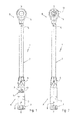
- FIG. 1 shows a torque tool 1 according to the invention, which has a tool shank 2 and a handle 3 arranged at an end portion A of the tool shank 2.
- a tool head 4 is arranged at a handle 3 opposite end portion B of the tool shank 2.
- the tool head 4 opens into a stem, not shown here, via which the tool head 4 is inserted in the end section B of the tool shank 2 and secured by a split pin 5.
- the splint 5 can also be a releasable connection means.
- the handle 3 is fixed via connecting means 6 at the end portion A of the tool shank 2.
- a Einstellkniller 7 is arranged at the free end of the handle 3.
- the Einstellkniller 7 is about the longitudinal direction X of the tool shank. 2 mounted rotatably within the handle 3 and secured against withdrawal from the handle 3 with Mattsmitteh 8.
- a display means 9 is arranged, via which the respectively set release torque can be displayed.
- the display means 9 on a scale 10, which in addition to individual markings also has Arabic numerals.
- the display means 9 itself is arranged inside the handle 3 and can be seen through a viewing window 11 of the handle 3.
- the viewing window 11 in the present case carries the unit of measurement Newtonmeter (Nm), which refers to the Arabic numerals of the display means 9.
- FIG. 2 shows the torque tool 1 in a comparison with the representation of FIG. 1 rotated 180 ° about the longitudinal direction X position.
- the tool head 4 has an output polygon 12 extending out of the tool head 4 and perpendicular to the longitudinal direction X.
- the output polygon 12 serves to accommodate unspecified Aufstecktechnikmaschinee here, for example Aufstecknadore, whereby the torque tool 1 can be coupled for example with a screw.
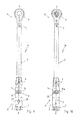
- FIG. 3 shows the torque tool 1 of FIG. 1 in partially cut representation.
- the sectional representation shows a view into the handle 3 and a portion of the tool shank 2 free.
- a clamping unit 13 is arranged within the handle 3, more closely within the tool shank 2 in the region of the handle 3.
- the respective release torque of the torque tool 1 is adjustable.
- the clamping unit 13 cooperates with the Einstellkniller 7, whereby the release torque is changed by turning the Einstellknaufs 7.
- FIG. 4 shows the torque tool 1 also in a partially cut representation, which is opposite to the view of FIG. 3 rotated by 90 ° about the longitudinal direction X around.
- the output polygon 12 extends away from the tool head 4.
- the output polygon 12 has a clamping element 12a.
- the clamping element 12a is spring-loaded in a manner not shown, whereby a on the Output polygon 12 plugged and not shown in detail tool, for example, is held in the form of a Aufstecknuss.
- FIG. 5 illustrates the clamping unit 13, which comprises a coil spring 14 and a spindle 15 and a spindle nut 16.
- the helical spring 14 extends in the longitudinal direction X of the tool shank 2.
- the helical spring 14 is supported at the end against the spindle nut 16, while the spindle nut 16 opposite end of the coil spring 14 loads a trigger mechanism, not shown, of the torque tool 1.
- the spindle 15 includes an external thread, with which the spindle nut 16 is engaged via a corresponding internal thread.
- the spindle 15 is rotatably supported by a spindle bearing 17 at the end portion A of the tool shank 2. While the rotatability of the spindle 15 is given by the spindle bearing 17, the spindle 15 is fixed in position in the longitudinal direction X of the tool shank 2.
- one of the spindle nut 16 opposite end portion of the spindle 15 is coupled to the adjustment knob 7.
- a rotation of the Einstellknaufs 7 thus causes a rotation of the spindle 15, whereby the spindle nut 16 on the slope of the intermeshing thread in position in the longitudinal direction X is displaced.
- the displacement of the spindle nut 16 causes the coil spring 14 is either compressed or relaxed depending on the direction of rotation of the Einstellknillers 7.
- the display means 9 can be seen between it and the handle 3.
- the display means 9 has a cylindrical design. Due to the cylindrical design, the display means 9 sets circumferentially around the end portion A of the tool shank 2 around. In the presentation of the FIG. 5 Furthermore, the viewing window 11 can be seen, which releases the view of the scale 10 of the display means 9 from outside the handle 3.
- FIG. 6 shows the detail of the FIG. 5 in a view rotated by 90 ° about the longitudinal direction X.
- FIG. 6 the representation of FIG. 3
- the adjusting unit 18 is in this case designed in the form of a screw.
- the setting unit 18 has a threaded portion with an external thread.
- the threaded portion of the actuating unit 18 is presently arranged within an extension 19 of the spindle nut 16.
- the extension 19 has for this purpose a corresponding internal thread, wherein the external thread of the adjusting unit 18 is at least partially engaged with the internal thread of the extension 19.
- the display means 9 has a receiving area 20, which in particular from FIG. 7 clearly shows.
- the adjusting unit 18 is rotatably mounted at its end opposite the threaded portion within the receiving area 20.
- the setting unit 18 for example, a thickened head portion, which is disposed within the receiving area 20.
- the setting unit 18 may have a groove, wherein the setting unit 18 is mounted, for example via a retaining ring within the receiving area 20 by the latter engages around the groove of the adjusting unit 18.
- FIG. 6 recognizable that the tool shank 2 in the region of the handle 3 has an opening 21, wherein the extension 19 of the spindle nut 16 protrudes through the opening 21 from the plane of the tool shank 2.
- FIG. 7 shows the display means 9 in its extracted from the torque tool 1 out shape.
- the display means 9 In extension of the receiving area 20, the display means 9 has a slot 22 extending in the longitudinal direction X.
- the slot 22 is necessary to provide the extension 19 of the spindle nut 16 corresponding clearance.
- a part of the scale 10 can be seen.
- FIG. 8 shows the detail of the FIG. 6 in an exploded view.
- the Einstellkniller 7 is removed from its storage within the handle 3, whereby the torque tool 1 an access 23 from the outside to the actuator 18 releases. Via the access 23, a tool 24 in the handle 3 be introduced.
- the tool 24 is an Allen wrench.
- the setting unit 18 has a tool attachment area 25, via which the setting unit 18 can be coupled to the tool 24.
- FIG. 9 shows an alternative embodiment of a torque tool 1a. Opposite the torque tool the FIGS. 1 to 8 this has a further viewing window 26 in the region of the handle 3. Thus, two in the longitudinal direction X of the tool shank 2 successively arranged viewing window 11, 26 are arranged on the handle 3. Through the additional window 26 through a number band 27 is at least partially visible.
- the number belt 27 is circumferentially arranged on an outer periphery of a located within the handle 3 portion of the Einstellknaufs 7.
- the number band 27 serves as a vernier to supplement the values of the currently set triggering torque displayed on the scale 10.
- the scale has 10 Arabic numerals in decimal increments, while the numerical band 27 comprises the same distance consecutively arranged circumferentially from 0 to 9.
- the numerical data to be taken from the number band 27 and the scale 10 form a common indication value for the set release torque.
- FIG. 10 shows a variant of the in the FIGS. 1 to 9 illustrated torque tools 1, 1a in the form of another torque tool 1b.
- the torque tool 1b present here has an additional viewing window 28 at the rear. This second viewing window 28 is thus opposite the first viewing window 11.
- the two viewing windows 11, 28 have different units of measurement, wherein the viewing window 28 of the FIG. 10 the Anglo-Saxon unit Lbfft carries.
- Via a correspondingly configured display means 9a which has a second scale 10a in addition to the first scale 10, in particular values for the country-specific units of measure are displayed.
- the scales 10, 10a may have different colors or at least different color designs.
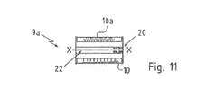
- FIG. 11 shows the display means 9a of FIG. 10 in its extracted from the torque tool 1 b form. Opposite the presentation of FIG. 7 it can be seen that this includes the further scale 10a in addition to the scale 10.
- the two scales 10, 10a are located on the cylindrically shaped display means 9a.
- the tool 24 is coupled to the adjusting unit 18 for adjusting the display means 9, 9a.
- the tool 24 is inserted or placed in or around the tool attachment area 25 of the setting unit 18.
- the rotation is converted via the interlocking threads of the extension 19 and the threaded portion of the actuator 18 in a longitudinal direction X directed movement. This allows the relative position of Display means 9, 9a relative to the spindle nut 16 changed and thus adjusted.
Landscapes
- Engineering & Computer Science (AREA)
- Mechanical Engineering (AREA)
- Details Of Spanners, Wrenches, And Screw Drivers And Accessories (AREA)
Applications Claiming Priority (1)
| Application Number | Priority Date | Filing Date | Title |
|---|---|---|---|
| DE202011050887U DE202011050887U1 (de) | 2011-08-03 | 2011-08-03 | Drehmomentwerkzeug |
Publications (2)
| Publication Number | Publication Date |
|---|---|
| EP2554330A2 true EP2554330A2 (fr) | 2013-02-06 |
| EP2554330A3 EP2554330A3 (fr) | 2018-03-21 |
Family
ID=44751924
Family Applications (1)
| Application Number | Title | Priority Date | Filing Date |
|---|---|---|---|
| EP12177586.0A Withdrawn EP2554330A3 (fr) | 2011-08-03 | 2012-07-24 | Clé dynamométrique |
Country Status (3)
| Country | Link |
|---|---|
| EP (1) | EP2554330A3 (fr) |
| CN (1) | CN102909684B (fr) |
| DE (1) | DE202011050887U1 (fr) |
Cited By (1)
| Publication number | Priority date | Publication date | Assignee | Title |
|---|---|---|---|---|
| WO2019226882A1 (fr) * | 2018-05-25 | 2019-11-28 | Apex Brands, Inc. | Clé dynamométrique dotée d'une poignée et/ou d'un dispositif de réglage améliorés |
Families Citing this family (2)
| Publication number | Priority date | Publication date | Assignee | Title |
|---|---|---|---|---|
| DE202013100263U1 (de) * | 2013-01-21 | 2014-04-24 | Hazet-Werk Hermann Zerver Gmbh & Co. Kg | Justierung eines Drehmomentschlüssels |
| DE202021103380U1 (de) * | 2021-06-23 | 2022-09-26 | Hazet-Werk Hermann Zerver Gmbh & Co. Kg | Drehmomentwerkzeug |
Citations (3)
| Publication number | Priority date | Publication date | Assignee | Title |
|---|---|---|---|---|
| US4541313A (en) | 1983-11-15 | 1985-09-17 | Norbar Torque Tools Limited | Adjustable torque wrench |
| DE202004006740U1 (de) | 2004-04-27 | 2004-07-22 | Eduard Wille Gmbh & Co. Kg | Drehmomentwerkzeuge mit Farbanzeige für verschiedene Einheiten |
| DE202010002176U1 (de) | 2010-02-08 | 2010-04-22 | Lai, Jin-Tsai | Handwerkzeug mit einstellbarem Drehmoment |
Family Cites Families (7)
| Publication number | Priority date | Publication date | Assignee | Title |
|---|---|---|---|---|
| SE470449B (sv) * | 1992-08-31 | 1994-04-11 | Sandvik Ab | Låsbar spännanordning för fjäder |
| US6119562A (en) * | 1999-07-08 | 2000-09-19 | Jenkins; Bradley G. | Electromechanical releasing torque wrench |
| US6722235B2 (en) * | 2002-02-25 | 2004-04-20 | Chih-Ching Hsieh | Torque wrench with a scale |
| DE20311811U1 (de) * | 2003-07-31 | 2003-09-25 | Hazet-Werk Hermann Zerver GmbH & Co. KG, 42857 Remscheid | Drehmomentschlüssel |
| JP2008036772A (ja) * | 2006-08-07 | 2008-02-21 | Kuken:Kk | 動力式ラチェットレンチ |
| DE202007006756U1 (de) * | 2007-05-10 | 2007-09-27 | Shen, Wei-Nan, Dali City | Schraubendreher mit zwei einstellbaren Drehmomentwerten |
| CN201769150U (zh) * | 2010-04-10 | 2011-03-23 | 吴展科 | 扭力扳手 |
-
2011
- 2011-08-03 DE DE202011050887U patent/DE202011050887U1/de not_active Expired - Lifetime
-
2012
- 2012-07-24 EP EP12177586.0A patent/EP2554330A3/fr not_active Withdrawn
- 2012-08-03 CN CN201210274442.6A patent/CN102909684B/zh not_active Expired - Fee Related
Patent Citations (3)
| Publication number | Priority date | Publication date | Assignee | Title |
|---|---|---|---|---|
| US4541313A (en) | 1983-11-15 | 1985-09-17 | Norbar Torque Tools Limited | Adjustable torque wrench |
| DE202004006740U1 (de) | 2004-04-27 | 2004-07-22 | Eduard Wille Gmbh & Co. Kg | Drehmomentwerkzeuge mit Farbanzeige für verschiedene Einheiten |
| DE202010002176U1 (de) | 2010-02-08 | 2010-04-22 | Lai, Jin-Tsai | Handwerkzeug mit einstellbarem Drehmoment |
Cited By (4)
| Publication number | Priority date | Publication date | Assignee | Title |
|---|---|---|---|---|
| WO2019226882A1 (fr) * | 2018-05-25 | 2019-11-28 | Apex Brands, Inc. | Clé dynamométrique dotée d'une poignée et/ou d'un dispositif de réglage améliorés |
| CN112154045A (zh) * | 2018-05-25 | 2020-12-29 | 艾沛克斯品牌公司 | 具有改进的手柄和/或调节器的扭矩扳手 |
| US11745319B2 (en) | 2018-05-25 | 2023-09-05 | Apex Brands, Inc. | Torque wrench with improved handle and/or adjuster |
| CN112154045B (zh) * | 2018-05-25 | 2024-05-03 | 艾沛克斯品牌公司 | 具有改进的手柄和/或调节器的扭矩扳手 |
Also Published As
| Publication number | Publication date |
|---|---|
| CN102909684B (zh) | 2014-12-17 |
| EP2554330A3 (fr) | 2018-03-21 |
| DE202011050887U1 (de) | 2011-09-07 |
| CN102909684A (zh) | 2013-02-06 |
Similar Documents
| Publication | Publication Date | Title |
|---|---|---|
| DE3700790C2 (fr) | ||
| EP2025296B1 (fr) | Clé dynamométrique, en particulier pour le domaine médical | |
| EP0649678A1 (fr) | Pipette à piston | |
| EP3538272B1 (fr) | Dispositif de dosage manuel | |
| EP4359172B1 (fr) | Outil dynamométrique | |
| DE9313282U1 (de) | Axialgewinderollkopf | |
| EP2554331A2 (fr) | Clé dynamométrique | |
| EP2554330A2 (fr) | Clé dynamométrique | |
| EP1767295A2 (fr) | Outil de coupe avec positionnement fin | |
| DE19928044C2 (de) | Prägestempel | |
| DE29811783U1 (de) | Variables Schraub- und/oder Bohrwerkzeug | |
| EP1502708B1 (fr) | Clé dynamométrique | |
| DE3335196C1 (de) | Spannvorrichtung für verzahnte Werkstücke | |
| EP2412478A2 (fr) | Dispositif de serrage avec amplification de puissance | |
| DE2843406A1 (de) | Vorrichtung zum drehwinkelgesteuerten anziehen einer schraubverbindung | |
| DE102013005940A1 (de) | Spannsystem für ein Mehrachsbearbeitungszentrum | |
| DE4204644C2 (de) | Vorrichtung zur Einstellung eines Werkzeuganschlags in einer Werkzeugspindel | |
| DE2122691C3 (de) | Stelleinrichtung, insbesondere zum Einstellen des Vorschubweges von Werkzeugträgern bei Werkzeugmaschinen | |
| DE102004061482B4 (de) | Schraubwerkzeug mit einstellbarer Drehmomentbegrenzungseinrichtung | |
| EP3062958B1 (fr) | Écrou de serrage de puissance | |
| DE3338217C2 (de) | Konterwerkzeug für Schraubverbindungen mit unterschiedlich großen Mehrkant-Mitnahmekörpern | |
| DE701434C (de) | Bohr- und Plandrehkopf | |
| DE4139650C2 (de) | Feinausbohrwerkzeug | |
| DE102021109191B4 (de) | Schraubwerkzeug mit mechanisch verstellbarer Drehmomentanzeige sowie zugehöriges Verfahren | |
| DE102017004043A1 (de) | Drehmomentschlüssel mit vordefinierter Drehmomentbegrenzung |
Legal Events
| Date | Code | Title | Description |
|---|---|---|---|
| PUAI | Public reference made under article 153(3) epc to a published international application that has entered the european phase |
Free format text: ORIGINAL CODE: 0009012 |
|
| AK | Designated contracting states |
Kind code of ref document: A2 Designated state(s): AL AT BE BG CH CY CZ DE DK EE ES FI FR GB GR HR HU IE IS IT LI LT LU LV MC MK MT NL NO PL PT RO RS SE SI SK SM TR |
|
| AX | Request for extension of the european patent |
Extension state: BA ME |
|
| PUAL | Search report despatched |
Free format text: ORIGINAL CODE: 0009013 |
|
| AK | Designated contracting states |
Kind code of ref document: A3 Designated state(s): AL AT BE BG CH CY CZ DE DK EE ES FI FR GB GR HR HU IE IS IT LI LT LU LV MC MK MT NL NO PL PT RO RS SE SI SK SM TR |
|
| AX | Request for extension of the european patent |
Extension state: BA ME |
|
| RIC1 | Information provided on ipc code assigned before grant |
Ipc: B25B 23/142 20060101AFI20180212BHEP |
|
| STAA | Information on the status of an ep patent application or granted ep patent |
Free format text: STATUS: THE APPLICATION IS DEEMED TO BE WITHDRAWN |
|
| 18D | Application deemed to be withdrawn |
Effective date: 20180922 |