EP2554433A2 - Dispositif d'éclairage pour véhicules automobiles - Google Patents
Dispositif d'éclairage pour véhicules automobiles Download PDFInfo
- Publication number
- EP2554433A2 EP2554433A2 EP12005682A EP12005682A EP2554433A2 EP 2554433 A2 EP2554433 A2 EP 2554433A2 EP 12005682 A EP12005682 A EP 12005682A EP 12005682 A EP12005682 A EP 12005682A EP 2554433 A2 EP2554433 A2 EP 2554433A2
- Authority
- EP
- European Patent Office
- Prior art keywords
- motor vehicle
- ignition
- alternator
- power supply
- vehicle according
- Prior art date
- Legal status (The legal status is an assumption and is not a legal conclusion. Google has not performed a legal analysis and makes no representation as to the accuracy of the status listed.)
- Withdrawn
Links
- 238000005286 illumination Methods 0.000 claims abstract description 16
- 230000033001 locomotion Effects 0.000 claims abstract description 5
- 238000005259 measurement Methods 0.000 abstract 2
- 230000003213 activating effect Effects 0.000 abstract 1
- 238000010586 diagram Methods 0.000 description 4
- 230000033228 biological regulation Effects 0.000 description 3
- 238000000034 method Methods 0.000 description 2
- 238000001514 detection method Methods 0.000 description 1
- 230000005611 electricity Effects 0.000 description 1
- 230000007613 environmental effect Effects 0.000 description 1
- 230000006698 induction Effects 0.000 description 1
- 239000000725 suspension Substances 0.000 description 1
- 230000001960 triggered effect Effects 0.000 description 1
Images


Classifications
-
- B—PERFORMING OPERATIONS; TRANSPORTING
- B60—VEHICLES IN GENERAL
- B60Q—ARRANGEMENT OF SIGNALLING OR LIGHTING DEVICES, THE MOUNTING OR SUPPORTING THEREOF OR CIRCUITS THEREFOR, FOR VEHICLES IN GENERAL
- B60Q1/00—Arrangement of optical signalling or lighting devices, the mounting or supporting thereof or circuits therefor
- B60Q1/02—Arrangement of optical signalling or lighting devices, the mounting or supporting thereof or circuits therefor the devices being primarily intended to illuminate the way ahead or to illuminate other areas of way or environments
- B60Q1/24—Arrangement of optical signalling or lighting devices, the mounting or supporting thereof or circuits therefor the devices being primarily intended to illuminate the way ahead or to illuminate other areas of way or environments for lighting other areas than only the way ahead
- B60Q1/247—Arrangement of optical signalling or lighting devices, the mounting or supporting thereof or circuits therefor the devices being primarily intended to illuminate the way ahead or to illuminate other areas of way or environments for lighting other areas than only the way ahead for illuminating the close surroundings of the vehicle, e.g. to facilitate entry or exit
-
- B—PERFORMING OPERATIONS; TRANSPORTING
- B60—VEHICLES IN GENERAL
- B60Q—ARRANGEMENT OF SIGNALLING OR LIGHTING DEVICES, THE MOUNTING OR SUPPORTING THEREOF OR CIRCUITS THEREFOR, FOR VEHICLES IN GENERAL
- B60Q2300/00—Indexing codes for automatically adjustable headlamps or automatically dimmable headlamps
- B60Q2300/10—Indexing codes relating to particular vehicle conditions
- B60Q2300/11—Linear movements of the vehicle
- B60Q2300/116—Vehicle at a stop
-
- B—PERFORMING OPERATIONS; TRANSPORTING
- B60—VEHICLES IN GENERAL
- B60Q—ARRANGEMENT OF SIGNALLING OR LIGHTING DEVICES, THE MOUNTING OR SUPPORTING THEREOF OR CIRCUITS THEREFOR, FOR VEHICLES IN GENERAL
- B60Q2300/00—Indexing codes for automatically adjustable headlamps or automatically dimmable headlamps
- B60Q2300/30—Indexing codes relating to the vehicle environment
- B60Q2300/31—Atmospheric conditions
- B60Q2300/314—Ambient light
Definitions
- Such lighting devices are e.g. known for lighting license plates.
- the surfaces of the vehicle body are provided with inscriptions, such as advertising or information of the commercial vehicle owner such as industry, phone number or other contact information.
- the object of the invention is to provide a vehicle with lighting device available, which on the one hand solves the recognizability of inscriptions in the dark, but on the other hand complies with the requirements of the applicable road traffic regulations.
- the vehicle has a control device, which has various tasks. On the one hand it monitors the ignition, on the other hand it can monitor a speed measuring device, eg a speedometer signal.
- the control unit then ensures that, when the alternator is switched on and / or energized - that is, upon detection of a current flowing from the alternator or to the alternator - and / or movement of the vehicle, the power supply to the illumination device is interrupted and the illumination device is switched off.
- the state of the switched on ignition also includes the case in which only the ignition key is inserted into the ignition lock without the starting process being triggered.
- ignition switched on also means that the ignition key can be turned in the ignition or otherwise moved without the engine being started.
- a lighting device 5 is mounted on a roof rack or a roof rail 2 on the vehicle roof 1 and radiates light 4 down on a side surface 3 of the vehicle.
- FIG. 2 the lighting device 5 is shown, which is attached to a roof rack 2 on the vehicle roof 1.
- the area to be illuminated with light 4 3 is here attached to a mounted on the roof rack 2 suspension 2a.
- the illumination device 5 has light sources 5a, preferably LEDs, which illuminate the surface 3 on which graphics and / or information are present.
- the emission angle is chosen so that, if possible, only illuminated the area 3 and corresponding, the road users disturbing or hindering stray light is avoided.
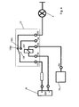
- FIG. 3 illustrates how the lighting device interacts with the on-board electrical system of the vehicle.
- the vehicle initially has a vehicle battery 10 for supplying the vehicle electrics and electronics. In particular, this supplies the energy for the ignition 11.
- the state of the ignition 11 and also the state of motion of the vehicle which is detected by a speed measuring device 12, for example by evaluating the speed signal, are detected and processed by a control unit 13.
- the vehicle battery also supplies a separate battery 14 with charging unit, which is used to supply power to the power source 16 for the lighting device 5 and ensures that the vehicle battery 10 is not emptied by the operation of the lighting 5.
- the supply of the lighting device 5 can be wired or wireless, such as induction.
- the battery 14 may also be charged by a solar device 15.
- the control device As soon as the ignition 11 is actuated or / and the speed sensor 12 signals a vehicle movement, the control device generates a switch-off signal, which ensures that the power source 16 interrupts the power supply of the lighting 5.
- the control unit 13 preferably queries the operating state of the vehicle continuously, so that switching on the lighting is possible again as soon as the ignition 11 is switched off and / or the vehicle is not moving.
- the illumination duration can be controlled via a timer.
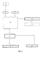
- FIGS. 4 and 5 more detailed representations of two embodiments are shown as a block diagram. These illustrate the process of interrupting the power supply in two examples.
- the control unit respectively comprises a switching device 13 ', which in the example shown is designed as a relay with a switch 136 which controls the switching positions 136a (switching on the lighting 5) and 136b (switching off the lighting 5) can take.
- the switching device 13 ' has a plurality of outputs 131-135.
- the first output 131 leading to the switch 136 is connected to the positive pole of the vehicle battery 16.
- the second leading to Umschaltmagneten 137 output 132 leads to the negative pole of the battery 16.
- the third output 133 in turn leads to Umschaltmagneten 137 of the relay and from there it is connected to the alternator 18 of the vehicle.
- the alternator 18 is energized, regardless of whether it generates electricity itself or a current flows to it, this can be detected via a tap 18a.
- the switching solenoid 137 is activated and the switch 136 is switched to the switching position 136b, so that the circuit is interrupted (positive pole of the battery 16 is at the unused output 134).
- the output 135 is connected to the changeover contact 136 a of the switch 136. At this output, the lighting device 5 is connected.
- the embodiment in FIG. 5 is different from the one in FIG. 4 merely in that the output 133 is not connected to the alternator, but to the ignition lock 11. Between the ignition lock 11 and the battery 16 there is a terminal 11a, which is referred to as "switched plus". If the ignition key is inserted into the ignition lock and / or moved into a switch-on position, a potential is applied at 11a, which causes a current flow from the battery 16 through the switching magnet 137. As a result, the switch 136 is moved to the switching position 136b and the current flow to the lighting 5 is interrupted.
- the invention thus provides a vehicle exterior lighting available that works safely in traffic and meets the legal requirements.
- the vehicle illuminated according to the invention also increases the safety of the vehicle itself, in particular against vandalism, since it is also visible in dark places. Due to the light striking the ground from the lighting, the immediate ground condition in the vehicle environment can be recognized even on low or not yet illuminated sidewalks for road users such as pedestrians and cyclists. As a result, danger spots can be detected faster and accidents avoided. In addition, the increase in visibility caused by an illuminated vehicle in the dark also leads to an increase in environmental safety of the aforementioned road users.
Landscapes
- Engineering & Computer Science (AREA)
- Mechanical Engineering (AREA)
- Lighting Device Outwards From Vehicle And Optical Signal (AREA)
Applications Claiming Priority (1)
| Application Number | Priority Date | Filing Date | Title |
|---|---|---|---|
| DE102011109489A DE102011109489A1 (de) | 2011-08-04 | 2011-08-04 | Beleuchtungseinrichtung für Kraftfahrzeuge |
Publications (2)
| Publication Number | Publication Date |
|---|---|
| EP2554433A2 true EP2554433A2 (fr) | 2013-02-06 |
| EP2554433A3 EP2554433A3 (fr) | 2014-03-12 |
Family
ID=46880544
Family Applications (1)
| Application Number | Title | Priority Date | Filing Date |
|---|---|---|---|
| EP12005682.5A Withdrawn EP2554433A3 (fr) | 2011-08-04 | 2012-08-03 | Dispositif d'éclairage pour véhicules automobiles |
Country Status (2)
| Country | Link |
|---|---|
| EP (1) | EP2554433A3 (fr) |
| DE (1) | DE102011109489A1 (fr) |
Cited By (2)
| Publication number | Priority date | Publication date | Assignee | Title |
|---|---|---|---|---|
| US9975473B2 (en) | 2015-07-08 | 2018-05-22 | GM Global Technology Operations LLC | Motor vehicle roof rail with integrated light system |
| DE102023207045A1 (de) * | 2023-07-25 | 2025-01-30 | Stellantis Auto Sas | Optische Signalvorrichtung zur Abgabe von Warnlichtsignalen |
Families Citing this family (1)
| Publication number | Priority date | Publication date | Assignee | Title |
|---|---|---|---|---|
| DE102014220630B4 (de) * | 2014-10-10 | 2023-03-30 | Süddeutsche Aluminium Manufaktur GmbH | Kraftfahrzeug mit einem Außenanbauteil |
Citations (2)
| Publication number | Priority date | Publication date | Assignee | Title |
|---|---|---|---|---|
| DE9212905U1 (de) | 1992-09-25 | 1992-11-26 | Szebrowski, Jürgen, 6072 Dreieich | Fahrzeugaußenflächen-Beleuchtung |
| DE29921620U1 (de) | 1999-12-09 | 2000-09-28 | Angele, Franz, 88410 Bad Wurzach | Ein zum Straßenverkehr zulassungsfähiger Getränke-Verkaufsautomat |
Family Cites Families (10)
| Publication number | Priority date | Publication date | Assignee | Title |
|---|---|---|---|---|
| AU663844B3 (en) * | 1995-02-06 | 1995-10-19 | Christopher John Martyr | Message sign controller |
| DE19725209A1 (de) * | 1997-06-14 | 1998-12-17 | Rudolf Eva | Kfz-Anzeigevorrichtung |
| DE10122977A1 (de) * | 2001-05-11 | 2003-01-23 | Helmut Egger | Werbe- und Informationsfahrzeug |
| WO2004006217A1 (fr) * | 2002-07-09 | 2004-01-15 | Leon Marthinus De Lange | Technique publicitaire et appareil a cet effet |
| DE20214278U1 (de) * | 2002-09-12 | 2003-01-30 | Kaspar, Lothar, Dipl.-Ing. (FH), 92345 Dietfurt | Umfeldbeleuchtung für Kraftfahrzeuge |
| US7143533B2 (en) * | 2003-07-09 | 2006-12-05 | Burke Malcolm A M | Motor vehicle decal display system |
| CN101689340A (zh) * | 2006-08-03 | 2010-03-31 | 兰德尔·J·拉纳姆 | 视频显示屏系统和显示信息的方法 |
| AT507337B1 (de) * | 2008-09-30 | 2011-01-15 | Martin Mag Doskar | Frei programmierbare anzeigetafel, insbesondere folie, zur anbringung an einem fahrzeug |
| US20110078933A1 (en) * | 2009-10-02 | 2011-04-07 | Lukawitz Jason J | Electronic license plate and information processing system |
| US8258704B2 (en) * | 2009-12-28 | 2012-09-04 | Brant Gregory S | Vehicle lighting display system |
-
2011
- 2011-08-04 DE DE102011109489A patent/DE102011109489A1/de not_active Ceased
-
2012
- 2012-08-03 EP EP12005682.5A patent/EP2554433A3/fr not_active Withdrawn
Patent Citations (2)
| Publication number | Priority date | Publication date | Assignee | Title |
|---|---|---|---|---|
| DE9212905U1 (de) | 1992-09-25 | 1992-11-26 | Szebrowski, Jürgen, 6072 Dreieich | Fahrzeugaußenflächen-Beleuchtung |
| DE29921620U1 (de) | 1999-12-09 | 2000-09-28 | Angele, Franz, 88410 Bad Wurzach | Ein zum Straßenverkehr zulassungsfähiger Getränke-Verkaufsautomat |
Cited By (2)
| Publication number | Priority date | Publication date | Assignee | Title |
|---|---|---|---|---|
| US9975473B2 (en) | 2015-07-08 | 2018-05-22 | GM Global Technology Operations LLC | Motor vehicle roof rail with integrated light system |
| DE102023207045A1 (de) * | 2023-07-25 | 2025-01-30 | Stellantis Auto Sas | Optische Signalvorrichtung zur Abgabe von Warnlichtsignalen |
Also Published As
| Publication number | Publication date |
|---|---|
| DE102011109489A1 (de) | 2013-02-07 |
| EP2554433A3 (fr) | 2014-03-12 |
Similar Documents
| Publication | Publication Date | Title |
|---|---|---|
| DE202006006192U1 (de) | Türbetätigungstaster | |
| DE102009048680A1 (de) | Leuchtanzeigevorrichtung und Verfahren zur Anzeige eines CO2-emissionsfreien Betriebs eines Kraftfahrzeugs | |
| DE102007048378B3 (de) | Vorrichtung zum Anschluss an eine Anhängersteckdose eines Kraftfahrzeugs | |
| EP2554433A2 (fr) | Dispositif d'éclairage pour véhicules automobiles | |
| DE202006019347U1 (de) | Anordnung zur Steuerung einer LED-Rundumkennleuchte | |
| DE10355046B4 (de) | Steuereinrichtung für Außenlichteinheiten von Fahrzeugen, insbesondere Kraftfahrzeugen | |
| EP2345466B1 (fr) | Eclairage pour roues porteuses | |
| DE3825178A1 (de) | Leuchten-reinigungsanlage fuer kraftfahrzeuge | |
| DE19729567C1 (de) | Gurtschloß an einem Sicherheitsgurt für Kraftfahrzeuge | |
| DE3939240A1 (de) | Automatisch ein- und ausschaltende beleuchtungsvorrichtung, insbesondere als parkleuchte fuer abgestellte fahrzeuge | |
| EP1258838A2 (fr) | Dispositif de détection de courant et son utilisation | |
| DE102019008661A1 (de) | Lichtassistenzsystem für ein Fahrzeug | |
| DE4042044C1 (en) | Power-saving illuminated traffic sign - has sec. cell battery charged by solar cell panel by day and lights up only in response to detection of motor vehicle headlamp(s) | |
| DE202007017871U1 (de) | Automatische Abschaltung des Bremslichtes | |
| DE102013001976B3 (de) | Lichtsignaleinrichtung für ein Fahrzeug, insbesondere für einen PKW | |
| DE10035686A1 (de) | Zusatz-Sicherheitsleuchteneinrichtung für Straßenfahrzeuge | |
| EP1008487A1 (fr) | Commutateur à commande par cellule photoélectrique avec dispositif d'intervention à durée limitée ou automatique pour la mise en circuit des lampes d'un véhicule à moteur | |
| DE1962093A1 (de) | Beleuchtungsanlage fuer Kraftfahrzeuge | |
| DE10213898C1 (de) | Dachzeichenanlage für ein Kraftfahrzeug | |
| DE102013102613A1 (de) | Vorrichtung zum Stoppen eines in falscher Richtung fahrenden Kraftfahrzeugs und Batterie zur Verwendung bei einer derartigen Vorrichtung | |
| DE202004001082U1 (de) | Hinweissystem an Kraftfahrzeugen | |
| DE20214278U1 (de) | Umfeldbeleuchtung für Kraftfahrzeuge | |
| EP1205360B1 (fr) | Ensemble d'interrupteurs pour une plaque d'immatriculation luminescente | |
| DE102009002696A1 (de) | Beleuchtungseinrichtung mit Standlicht | |
| DE19957159C1 (de) | Elektronisches Blinkersystem für ein Fahrrad |
Legal Events
| Date | Code | Title | Description |
|---|---|---|---|
| PUAI | Public reference made under article 153(3) epc to a published international application that has entered the european phase |
Free format text: ORIGINAL CODE: 0009012 |
|
| AK | Designated contracting states |
Kind code of ref document: A2 Designated state(s): AL AT BE BG CH CY CZ DE DK EE ES FI FR GB GR HR HU IE IS IT LI LT LU LV MC MK MT NL NO PL PT RO RS SE SI SK SM TR |
|
| AX | Request for extension of the european patent |
Extension state: BA ME |
|
| PUAL | Search report despatched |
Free format text: ORIGINAL CODE: 0009013 |
|
| AK | Designated contracting states |
Kind code of ref document: A3 Designated state(s): AL AT BE BG CH CY CZ DE DK EE ES FI FR GB GR HR HU IE IS IT LI LT LU LV MC MK MT NL NO PL PT RO RS SE SI SK SM TR |
|
| AX | Request for extension of the european patent |
Extension state: BA ME |
|
| RIC1 | Information provided on ipc code assigned before grant |
Ipc: G09F 21/04 20060101ALI20140204BHEP Ipc: B60Q 1/24 20060101AFI20140204BHEP |
|
| STAA | Information on the status of an ep patent application or granted ep patent |
Free format text: STATUS: THE APPLICATION IS DEEMED TO BE WITHDRAWN |
|
| 18D | Application deemed to be withdrawn |
Effective date: 20140913 |