EP2554442A1 - Vorrichtung zum Bremsen von Schwungradsystemen und Verfahren zur Ableitung von darin gespeicherter Energie - Google Patents
Vorrichtung zum Bremsen von Schwungradsystemen und Verfahren zur Ableitung von darin gespeicherter Energie Download PDFInfo
- Publication number
- EP2554442A1 EP2554442A1 EP12178714A EP12178714A EP2554442A1 EP 2554442 A1 EP2554442 A1 EP 2554442A1 EP 12178714 A EP12178714 A EP 12178714A EP 12178714 A EP12178714 A EP 12178714A EP 2554442 A1 EP2554442 A1 EP 2554442A1
- Authority
- EP
- European Patent Office
- Prior art keywords
- flywheel
- sensor
- energy storage
- storage assembly
- fluid source
- Prior art date
- Legal status (The legal status is an assumption and is not a legal conclusion. Google has not performed a legal analysis and makes no representation as to the accuracy of the status listed.)
- Withdrawn
Links
Images
Classifications
-
- B—PERFORMING OPERATIONS; TRANSPORTING
- B60—VEHICLES IN GENERAL
- B60K—ARRANGEMENT OR MOUNTING OF PROPULSION UNITS OR OF TRANSMISSIONS IN VEHICLES; ARRANGEMENT OR MOUNTING OF PLURAL DIVERSE PRIME-MOVERS IN VEHICLES; AUXILIARY DRIVES FOR VEHICLES; INSTRUMENTATION OR DASHBOARDS FOR VEHICLES; ARRANGEMENTS IN CONNECTION WITH COOLING, AIR INTAKE, GAS EXHAUST OR FUEL SUPPLY OF PROPULSION UNITS IN VEHICLES
- B60K6/00—Arrangement or mounting of plural diverse prime-movers for mutual or common propulsion, e.g. hybrid propulsion systems comprising electric motors and internal combustion engines
- B60K6/08—Prime-movers comprising combustion engines and mechanical or fluid energy storing means
- B60K6/10—Prime-movers comprising combustion engines and mechanical or fluid energy storing means by means of a chargeable mechanical accumulator, e.g. flywheel
- B60K6/105—Prime-movers comprising combustion engines and mechanical or fluid energy storing means by means of a chargeable mechanical accumulator, e.g. flywheel the accumulator being a flywheel
-
- B—PERFORMING OPERATIONS; TRANSPORTING
- B60—VEHICLES IN GENERAL
- B60T—VEHICLE BRAKE CONTROL SYSTEMS OR PARTS THEREOF; BRAKE CONTROL SYSTEMS OR PARTS THEREOF, IN GENERAL; ARRANGEMENT OF BRAKING ELEMENTS ON VEHICLES IN GENERAL; PORTABLE DEVICES FOR PREVENTING UNWANTED MOVEMENT OF VEHICLES; VEHICLE MODIFICATIONS TO FACILITATE COOLING OF BRAKES
- B60T1/00—Arrangements of braking elements, i.e. of those parts where braking effect occurs specially for vehicles
- B60T1/02—Arrangements of braking elements, i.e. of those parts where braking effect occurs specially for vehicles acting by retarding wheels
- B60T1/10—Arrangements of braking elements, i.e. of those parts where braking effect occurs specially for vehicles acting by retarding wheels by utilising wheel movement for accumulating energy, e.g. driving air compressors
-
- B—PERFORMING OPERATIONS; TRANSPORTING
- B60—VEHICLES IN GENERAL
- B60T—VEHICLE BRAKE CONTROL SYSTEMS OR PARTS THEREOF; BRAKE CONTROL SYSTEMS OR PARTS THEREOF, IN GENERAL; ARRANGEMENT OF BRAKING ELEMENTS ON VEHICLES IN GENERAL; PORTABLE DEVICES FOR PREVENTING UNWANTED MOVEMENT OF VEHICLES; VEHICLE MODIFICATIONS TO FACILITATE COOLING OF BRAKES
- B60T7/00—Brake-action initiating means
- B60T7/12—Brake-action initiating means for automatic initiation; for initiation not subject to will of driver or passenger
- B60T7/22—Brake-action initiating means for automatic initiation; for initiation not subject to will of driver or passenger initiated by contact of vehicle, e.g. bumper, with an external object, e.g. another vehicle, or by means of contactless obstacle detectors mounted on the vehicle
-
- F—MECHANICAL ENGINEERING; LIGHTING; HEATING; WEAPONS; BLASTING
- F03—MACHINES OR ENGINES FOR LIQUIDS; WIND, SPRING, OR WEIGHT MOTORS; PRODUCING MECHANICAL POWER OR A REACTIVE PROPULSIVE THRUST, NOT OTHERWISE PROVIDED FOR
- F03G—SPRING, WEIGHT, INERTIA OR LIKE MOTORS; MECHANICAL-POWER PRODUCING DEVICES OR MECHANISMS, NOT OTHERWISE PROVIDED FOR OR USING ENERGY SOURCES NOT OTHERWISE PROVIDED FOR
- F03G7/00—Mechanical-power-producing mechanisms, not otherwise provided for or using energy sources not otherwise provided for
- F03G7/08—Mechanical-power-producing mechanisms, not otherwise provided for or using energy sources not otherwise provided for recovering energy derived from swinging, rolling, pitching or like movements, e.g. from the vibrations of a machine
- F03G7/081—Mechanical-power-producing mechanisms, not otherwise provided for or using energy sources not otherwise provided for recovering energy derived from swinging, rolling, pitching or like movements, e.g. from the vibrations of a machine recovering energy from moving road or rail vehicles, e.g. collecting vehicle vibrations in the vehicle tyres or shock absorbers
-
- F—MECHANICAL ENGINEERING; LIGHTING; HEATING; WEAPONS; BLASTING
- F16—ENGINEERING ELEMENTS AND UNITS; GENERAL MEASURES FOR PRODUCING AND MAINTAINING EFFECTIVE FUNCTIONING OF MACHINES OR INSTALLATIONS; THERMAL INSULATION IN GENERAL
- F16D—COUPLINGS FOR TRANSMITTING ROTATION; CLUTCHES; BRAKES
- F16D57/00—Liquid-resistance brakes; Brakes using the internal friction of fluids or fluid-like media, e.g. powders
- F16D57/06—Liquid-resistance brakes; Brakes using the internal friction of fluids or fluid-like media, e.g. powders comprising a pump circulating fluid, braking being effected by throttling of the circulation
-
- Y—GENERAL TAGGING OF NEW TECHNOLOGICAL DEVELOPMENTS; GENERAL TAGGING OF CROSS-SECTIONAL TECHNOLOGIES SPANNING OVER SEVERAL SECTIONS OF THE IPC; TECHNICAL SUBJECTS COVERED BY FORMER USPC CROSS-REFERENCE ART COLLECTIONS [XRACs] AND DIGESTS
- Y02—TECHNOLOGIES OR APPLICATIONS FOR MITIGATION OR ADAPTATION AGAINST CLIMATE CHANGE
- Y02T—CLIMATE CHANGE MITIGATION TECHNOLOGIES RELATED TO TRANSPORTATION
- Y02T10/00—Road transport of goods or passengers
- Y02T10/60—Other road transportation technologies with climate change mitigation effect
- Y02T10/62—Hybrid vehicles
-
- Y—GENERAL TAGGING OF NEW TECHNOLOGICAL DEVELOPMENTS; GENERAL TAGGING OF CROSS-SECTIONAL TECHNOLOGIES SPANNING OVER SEVERAL SECTIONS OF THE IPC; TECHNICAL SUBJECTS COVERED BY FORMER USPC CROSS-REFERENCE ART COLLECTIONS [XRACs] AND DIGESTS
- Y10—TECHNICAL SUBJECTS COVERED BY FORMER USPC
- Y10T—TECHNICAL SUBJECTS COVERED BY FORMER US CLASSIFICATION
- Y10T74/00—Machine element or mechanism
- Y10T74/21—Elements
- Y10T74/2117—Power generating-type flywheel
Definitions
- the present invention relates primarily to an apparatus for braking flywheel systems and to a method for dissipating energy stored in flywheel systems.
- One possible supplemental power source for vehicles may be such as a mechanical flywheel.
- Flywheel energy storage systems work by accelerating a rotor or disc to very high speeds via an external device, such as an internal combustion engine, electromagnet, or axle.
- the available rotational energy in the flywheel can be transferred into mechanical energy, thus providing a power source to the driveline.
- the rotating flywheel can also be used as a power sink during braking by transferring the driveline's kinetic energy into rotational energy.
- the energy transfers depend on the intended driveline's behavior.
- the rotational speed of the flywheel is reduced as a consequence of the principle of conservation of energy; adding energy to the flywheel correspondingly results in an increase in the speed of the flywheel.
- a flywheel energy storage system can be connected to the front or rear axle of a vehicle.
- braking energy is used to speed up the flywheel to a high-speed rotational state.
- the high-speed rotational speed may be about up to 60,000 revolutions per minute.
- the rotational energy from the flywheel is transferred to mechanical energy to the driving wheels of the vehicle via a specially designed device, like a continuously variable transmission, for example.
- flywheels store a tremendous amount of energy. This energy typically is dissipated in a highly controlled manner at predetermined times. However, there may be certain circumstances when this energy needs to be very quickly dissipated in order to prevent or reduce damage to the flywheel itself or secondary systems. Events such as vehicle crashes are one circumstance where the energy in the flywheel must be dissipated. In any circumstance where the energy in the flywheel must be reduced or brought to zero, it must be done so in a controlled but rapid method so as to avoid an abrupt stop and/or damage to the flywheel or associated parts.
- the present invention is directed to a flywheel energy storage assembly comprising a flywheel rotatably disposed in a flywheel housing, a fluid source, a braking actuator in fluid communication with the fluid source and an interior of the flywheel housing, a sensor, and a controller in communication with the sensor and the braking actuator.
- the controller is configured to direct the braking actuator in response to a stimulus detected by the sensor to facilitate fluid communication between the fluid source and the interior of the flywheel housing.
- the present invention is directed to a flywheel energy storage assembly for a vehicle comprising a flywheel rotatably disposed in a flywheel housing, the flywheel forming a portion of a driveline of the vehicle and an interior of the flywheel housing having a vacuum being drawn thereupon, a pressure relief valve disposed in the flywheel housing, a vessel containing a liquid, a valve in fluid communication with the vessel and the interior of the flywheel housing, a pre-crash detection sensor, and a controller in communication with the pre-crash detection sensor and the braking actuator.
- the controller is configured to direct the braking actuator in response to a stimulus detected by the pre-crash detection sensor to facilitate fluid communication between the vessel and the interior of the flywheel housing.
- the present invention also is directed to a method of dissipating energy stored in a flywheel assembly.
- the method comprises the steps of providing the flywheel assembly including a flywheel rotatably disposed in a flywheel housing, providing a fluid source, providing a braking actuator in fluid communication with the fluid source and an interior of the flywheel housing, providing a sensor, providing a controller in communication with the sensor and the braking actuator, detecting a stimulus using the sensor, communicating a signal to the controller from the sensor in response to the stimulus, opening the braking actuator using the controller in response to the signal, causing the fluid source to be in fluid communication with the interior of the flywheel housing, and dissipating energy stored in the flywheel assembly by delivering a fluid from the fluid source to the interior of the flywheel housing.
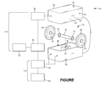
- FIGURE is a schematic view of a flywheel energy storage system according to an embodiment of the present invention.
- the FIGURE illustrates a flywheel energy storage assembly 10 for a vehicle (not shown) according to an embodiment of the invention.
- the flywheel energy storage assembly 10 includes a flywheel assembly 12, a flywheel housing 14, a flywheel braking assembly 16, and a flywheel controller assembly 18.
- the flywheel energy storage assembly 10 is configured for use with the vehicle; however, it is understood that the flywheel energy storage assembly 10 may be used in other applications.
- the flywheel assembly 12 includes a first flywheel 20, a second flywheel 22, and an axle 24.
- the flywheel assembly 12 is balanced to permit rotation in a high-speed rotational state.
- the flywheel assembly 12 is rotatably disposed coupled to the flywheel housing 14 and is supported therein by at least two bearings 26. As shown in the FIGURE, the flywheel assembly 12 includes two flywheels 20, 22; however, it is understood that the flywheel assembly 12 may include any number of flywheels.
- the first flywheel 20 is a disc shaped or cylindrical shaped member.
- the first flywheel 20 is disposed on a first end of the axle 24 and is in driving engagement therewith.
- a reinforcement band 28 is disposed on an outer edge of the first flywheel 20; however, it is understood that the first flywheel 20 may not include the reinforcement band 28.
- the first flywheel 20 is formed by casting and machining a metal; however, it is understood that other processes and materials, such as forming the first flywheel 20 from a composite, may be used.
- the second flywheel 22 is a disc shaped or cylindrical shaped member.
- the second flywheel 22 is disposed on a second end of the axle 24 and is in driving engagement therewith.
- a reinforcement band 30 is disposed on an outer edge of the second flywheel 22; however, it is understood that the second flywheel 22 may not include the reinforcement band 30.
- the second flywheel 22 is formed by casting and machining a metal; however, it is understood that other processes and materials, such as forming the second flywheel 22 from a composite, may be used.
- the axle 24 is a substantially cylindrical member disposed through the flywheels 20, 22 and is drivingly engaged therewith; however, it is understood that the axle 24 may have other shapes and may be integrally formed with the flywheels 20, 22.
- the axle 24 may be formed from a material dissimilar to a material used to form the flywheels 20, 22.
- the bearings 26 are disposed on the axle 24 and an inner race of each of the bearings 26 is in driving engagement with the axle 24.
- the axle 24 is configured to permit a torque to be applied thereto.
- the axle 24 may be configured to permit the torque to be applied thereto with a gear (not shown) fitted to the axle 24, with an armature (not shown) of an electric motor or generator, a transmission input or a transmission output, or another device.
- the reinforcement bands 28, 30 are respectively disposed on the outer edges of the flywheels 20, 22.
- the reinforcement bands 28, 30 resist forces applied to the flywheels 20, 22 when the flywheels 20, 22 are placed in the high rotational state.
- the reinforcement bands 28, 30 may be formed from metal having a high tensile strength, a composite material comprising a carbon fiber, or other materials capable of resisting the forces applied to the flywheels 20, 22 when the flywheels 20, 22 are placed in the high rotational state.
- the bearings 26 are disposed between the flywheel housing 14 and the axle 20, and rotatably support the flywheels 20, 22 within the flywheel housing 14. An outer race of each of the bearings 26 is rigidly coupled to the flywheel housing 14.
- the bearings 26 capable of supporting the flywheels 20, 22 in the high-speed rotational state are conventional and well known in the art.
- the bearings 26 may be non-contact bearings, such as a fluid bearing or a magnetic bearing.
- the bearings 26 may also be a contact bearing, such as a ceramic bearing.
- the flywheel housing 14 is a hollow body which encloses the flywheel assembly 12. As shown in the FIGURE, the flywheel housing 14 comprises a first portion 32 and a second portion 34; however, it is understood that the flywheel housing 14 may be formed from any number of components.
- the flywheel housing 14 forms a portion of a vehicle driveline (not shown), and it is understood that the flywheel housing 14 may be coupled to or integrated with a power source (not shown) or a transmission (not shown) of the vehicle.
- a vacuum is drawn on the flywheel housing 14.
- the flywheel housing 14 is configured with a vacuum port 35 to facilitate the vacuum being drawn on the flywheel housing 14.
- the flywheel housing 14 also includes a pressure relief valve 36 disposed therein.
- the pressure relief valve 36 is conventional and well known in the art.
- the flywheel braking assembly 16 may be coupled to or is in fluid communication with the flywheel housing 14.
- the first portion 32 is a hollow member which partially encloses the flywheel assembly 12 when the flywheel energy storage assembly 10 is in an assembled state. As shown in the FIGURE, the first portion 32 is substantially rectangular in shape; however it is understood that the first portion 32 may be any shape.
- the first portion 32 is formed by casting and machining a metal. Alternately, the first portion 32 may be formed from other materials, such as a composite, for example, using other processes. Further, the first portion 32 may be formed from a plurality of components coupled together.
- the first portion 32 include a mounting protuberance 37 extending therefrom having two bearing journals 38 formed therein for supporting the bearings 26.
- the mounting protuberance 37 is an elongate portion of the first portion 32 extending from an inner surface thereof. Further, it is understood that the bearing journals 38 and the mounting protuberance 37 may support seals or other components.
- the second portion 34 is a hollow member which partially encloses the flywheel assembly 12 when the flywheel energy storage assembly 10 is in an assembled state. As shown in the FIGURE, the second portion 34 is substantially rectangular in shape; however it is understood that the second portion 34 may be any shape.
- the second portion 34 is formed by casting and machining a metal. Alternately, the second portion 34 may be formed from other materials, such as a composite, for example, using other processes. Further, the second portion 34 may be formed from a plurality of components coupled together.
- the second portion 34 include a mounting protuberance 40 extending therefrom having two bearing journals 42 formed therein for supporting the bearings 26.
- the mounting protuberance 40 is an elongate portion of the second portion 34 extending from an inner surface thereof. Further, it is understood that the bearing journals 42 and the mounting protuberance 40 may support seals or other components.
- the flywheel braking assembly 16 includes a fluid source 44 and a braking actuator 46.
- the flywheel braking assembly 16 cooperates with the flywheel controller assembly 18 to deliver a fluid to an interior volume 48 of the flywheel housing 14.
- the flywheel braking assembly 16 may be coupled to the flywheel housing 14. Alternately, the flywheel braking assembly 16 may be in fluid communication with the interior volume 48 and located elsewhere on the vehicle.
- the fluid source 44 is in fluid communication with the braking actuator 46.
- the fluid source 44 supplies a braking fluid to the braking actuator 46.
- the fluid source 44 may be one of a vessel, a conduit forming a portion of a vehicle fluid system, and an ambient environment the vehicle is disposed in.
- the fluid source 44 is the vessel, the fluid source 44 contains a pre-measured volume of the braking fluid.
- the pre-measured volume of the braking fluid is capable of dissipating an amount of energy stored in the first flywheel 20 and the second flywheel 22.
- the conduit may form a portion of one of a vehicle coolant system, a vehicle air conditioning system, and a vehicle lubrication system, which contain the braking fluid.
- the braking fluid may be water, a water based mixture of liquids, a coolant, a refrigerant, a lubricant, or other liquids.
- the fluid source 44 is the ambient environment the vehicle is disposed in, the braking fluid is air.
- the braking actuator 46 is a pneumatic control valve in fluid communication with the interior volume 48 of the flywheel housing 14 and the fluid source 44. Alternately, the braking actuator 46 may be any other type of valve.
- the flywheel controller assembly 18 is in communication with the braking actuator 46 and directs the braking actuator 46 to open or close in response to a stimulus. As a non-limiting example, the braking actuator 46 is capable of opening or closing in about 100 milliseconds. When the braking actuator 46 is closed, the interior volume 48 of the flywheel housing 14 is isolated from the fluid source 44. When the braking actuator 46 is open, the interior volume 48 of the flywheel housing 14 is in fluid communication with the fluid source 44. A pressure differential between the fluid source 44 and the interior volume 48 of the flywheel housing 14 facilitates delivery of the braking fluid to the interior volume 48 of the flywheel housing 14.
- the flywheel controller assembly 18 includes a flywheel speed sensor 50, an actuation sensor 52, and a controller 54.
- the flywheel controller assembly 18 forms a portion of a vehicle control system (not shown).
- the braking actuator 46, the flywheel speed sensor 50, and the actuation sensor 52 are in communication with the controller 54.
- the flywheel speed sensor 50 detects a rotational speed of the at least one of the first flywheel 20, the second flywheel 22, the axle 24, or a rotating component in driving engagement with one of the first flywheel 20 and the second flywheel 22.
- the flywheel speed sensor 50 is a conventional sensor and well known in the art.
- the flywheel speed sensor 50 generates a speed signal in response to the rotational speed.
- the speed signal generated by the flywheel speed sensor 50 is received by the controller 50.
- the actuation sensor 52 detects the stimulus the vehicle is exposed to.
- the actuation sensor 52 may be one of a plurality of sensor types that are conventional and well known in the art.
- the actuation sensor 52 may be one of a lateral acceleration sensor, a longitudinal acceleration sensor, a vehicle roll rate sensor, an airbag deployment detection sensor, a pre-crash detection sensor, and a radar sensor.
- the stimulus indicates the vehicle has crashed or a crash is imminent; however, it is understood that the stimulus may indicate other situations in which the amount of energy stored in the first flywheel 20 and the second flywheel 22 must be dissipated.
- the actuation sensor 52 generates a sensor signal in response to the stimulus.
- the sensor signal generated by the actuation sensor 52 is received by the controller 50.
- the controller 50 receives the speed signal and the sensor signal.
- the controller 50 is conventional and well known in the art.
- the controller 50 includes an algorithm or a set of instructions that determine when the braking actuator 46 should be opened in response to at least one of the speed signal and the sensor signal.
- the controller 50 may open the braking actuator 46 for a predetermined amount of time, intermittently, or to release a predetermined amount of the braking fluid.
- the controller 50 may also be directed to open the braking actuator by the vehicle control system.
- the flywheel energy storage assembly 10 facilitates safely dissipating energy stored in the flywheels 20, 22 in a rapid and controlled manner without significantly increasing a cost of the flywheel energy storage assembly 10.
- a process for dissipating energy stored in the flywheels 20, 22 begins with the actuation sensor 52 detecting the stimulus. In response to the stimulus, the actuation sensor generates the sensor signal, which is communicated to the controller 54. The controller 54 uses the sensor signal to trigger a procedure which dissipates the energy in the flywheels 20, 22. Typically, when the controller 54 triggers the procedure which dissipates the energy in the flywheels 20, 22, the flywheels 20, 22 are in the high-speed rotational state.
- the process for dissipating energy stored in the flywheels 20, 22 militates against damage which may be caused to the flywheel energy storage assembly 10 or other portions of a vehicle the flywheel energy storage assembly 10 is incorporated in. Such damage may occur if a portion of the flywheel energy storage assembly 10 becomes deformed as a result of a crash, and such damage can be reduced or eliminated if the flywheels 20, 22 are stopped or significantly slowed from the high speed rotational state.
- the flywheel energy storage assembly 10 must have a relatively quick reaction and performance time as there is only a short amount of time available between detection of the stimulus and any damage which may be caused to the flywheel energy storage assembly 10. In this short time, the flywheels 20, 22 must be subject to a quick but effective means for dissipating the energy stored in the flywheels 20, 22.
- the energy stored in the flywheels 20, 22 may be quickly and effectively dissipated by exposing the flywheels 20, 22 to the braking fluid.
- the braking fluid may be air.
- the interior volume 48 the flywheels 20, 22 are disposed in may have a vacuum drawn upon to limit churning losses by friction between the flywheels 20,22 and surrounding air.
- the controller 54 directs the braking actuator 46 to open, which release the vacuum and exposes the flywheels 20, 22 and the interior volume 48 to the ambient air.
- the braking actuator 46 may be in fluid communication with the fluid source 44 which is the vessel containing pressurized air.
- the fluid source 44 may be an air reservoir or a conduit containing pressurized air.
- the controller 54 directs the braking actuator 46 to open, the pressurized air enters the interior volume 48 and functions to brake the flywheels 20, 22 and remove heat from the flywheels 20, 22 and the interior volume 48.
- the heat may be generated by braking the flywheels 20, 22.
- Air in a non-heated state is relatively dense, and effectively acts as a brake to dissipate energy stored in the flywheels 20, 22.
- air directed into the interior volume 48 may be highly turbulent, which also facilitates in braking the flywheels 20, 22.
- Air is not the only fluid that may be used to dissipate energy stored in the flywheels 20, 22. If air is not available, water from a reservoir or an engine cooling system may be injected into the interior volume 48. The water can exert large a braking moment on the flywheels 20, 22. Water injected into the flywheel housing 14 while the flywheels 20, 22 are in the high speed rotational state will result in enough energy dissipation that at least some of the water will be converted to steam. The steam can exit the flywheel housing 14 through the pressure relief valve 36 to relieve pressure that may be generated during braking of the flywheels 20, 22. Since a vaporization heat of water is quite high, only a limited quantity of water is needed to keep the system at relative low temperatures (around 100°C). Further, the fluid source 44 may contain a pre-measured volume of water, the pre-measured volume of water capable of dissipating the amount of energy stored in the flywheels 20, 22
- air and water may be used in combination, such as in series or in parallel.
- air and water may be used in combination, such as in series or in parallel.
- other fluids such as the braking fluid other than air and water.
- a refrigerant such as an engine lubricant or a transmission lubricant
- a vehicle coolant such as an engine lubricant or a transmission lubricant
- the invention may include one or several of the following aspects:
Landscapes
- Engineering & Computer Science (AREA)
- Mechanical Engineering (AREA)
- Chemical & Material Sciences (AREA)
- Combustion & Propulsion (AREA)
- Transportation (AREA)
- General Engineering & Computer Science (AREA)
- Hybrid Electric Vehicles (AREA)
- Arrangement Or Mounting Of Propulsion Units For Vehicles (AREA)
Applications Claiming Priority (1)
| Application Number | Priority Date | Filing Date | Title |
|---|---|---|---|
| US201161513701P | 2011-08-01 | 2011-08-01 |
Publications (1)
| Publication Number | Publication Date |
|---|---|
| EP2554442A1 true EP2554442A1 (de) | 2013-02-06 |
Family
ID=47002531
Family Applications (1)
| Application Number | Title | Priority Date | Filing Date |
|---|---|---|---|
| EP12178714A Withdrawn EP2554442A1 (de) | 2011-08-01 | 2012-07-31 | Vorrichtung zum Bremsen von Schwungradsystemen und Verfahren zur Ableitung von darin gespeicherter Energie |
Country Status (2)
| Country | Link |
|---|---|
| US (1) | US20130192915A1 (de) |
| EP (1) | EP2554442A1 (de) |
Cited By (1)
| Publication number | Priority date | Publication date | Assignee | Title |
|---|---|---|---|---|
| WO2018216038A1 (en) * | 2017-05-26 | 2018-11-29 | Emilio Leonardi | Kinetic energy accumulator |
Families Citing this family (3)
| Publication number | Priority date | Publication date | Assignee | Title |
|---|---|---|---|---|
| US9578860B2 (en) | 2013-08-23 | 2017-02-28 | Allen Fly Fishing Llc | Fly reel with ratcheting drag system |
| CN106080558A (zh) * | 2016-07-20 | 2016-11-09 | 王占海 | 机动车刹车避撞系统 |
| US20190011001A1 (en) * | 2017-07-06 | 2019-01-10 | Amber Kinetics, Inc. | Emergency Braking of a Flywheel |
Citations (4)
| Publication number | Priority date | Publication date | Assignee | Title |
|---|---|---|---|---|
| DE2752390A1 (de) * | 1977-01-17 | 1978-07-27 | Lohnert Guenter Dr | Sicherheits-schwungrad |
| CA1144784A (en) * | 1981-08-31 | 1983-04-19 | Robert D. De Pencier | Safety housing for rotating objects |
| DE102005059903A1 (de) * | 2005-12-15 | 2007-06-28 | Robert Bosch Gmbh | Sicherheitseinrichtung für Kraftfahrzeuge |
| GB2449282A (en) * | 2007-05-17 | 2008-11-19 | Flybrid Systems Llp | High speed flywheel containment |
Family Cites Families (3)
| Publication number | Priority date | Publication date | Assignee | Title |
|---|---|---|---|---|
| US5767595A (en) * | 1993-11-08 | 1998-06-16 | Rosen Motors, L.P. | Flywheel system for mobile energy storage |
| US5559381A (en) * | 1993-11-08 | 1996-09-24 | Rosen Motors, L.P. | Flywheel support system for mobile energy storage |
| US8726762B2 (en) * | 2010-06-28 | 2014-05-20 | Honeywell International Inc. | Tunable mass damper for use with a reaction wheel assembly |
-
2012
- 2012-07-31 US US13/563,061 patent/US20130192915A1/en not_active Abandoned
- 2012-07-31 EP EP12178714A patent/EP2554442A1/de not_active Withdrawn
Patent Citations (4)
| Publication number | Priority date | Publication date | Assignee | Title |
|---|---|---|---|---|
| DE2752390A1 (de) * | 1977-01-17 | 1978-07-27 | Lohnert Guenter Dr | Sicherheits-schwungrad |
| CA1144784A (en) * | 1981-08-31 | 1983-04-19 | Robert D. De Pencier | Safety housing for rotating objects |
| DE102005059903A1 (de) * | 2005-12-15 | 2007-06-28 | Robert Bosch Gmbh | Sicherheitseinrichtung für Kraftfahrzeuge |
| GB2449282A (en) * | 2007-05-17 | 2008-11-19 | Flybrid Systems Llp | High speed flywheel containment |
Cited By (1)
| Publication number | Priority date | Publication date | Assignee | Title |
|---|---|---|---|---|
| WO2018216038A1 (en) * | 2017-05-26 | 2018-11-29 | Emilio Leonardi | Kinetic energy accumulator |
Also Published As
| Publication number | Publication date |
|---|---|
| US20130192915A1 (en) | 2013-08-01 |
Similar Documents
| Publication | Publication Date | Title |
|---|---|---|
| EP2554442A1 (de) | Vorrichtung zum Bremsen von Schwungradsystemen und Verfahren zur Ableitung von darin gespeicherter Energie | |
| US20030104900A1 (en) | Automotive internal combustion engine control system | |
| JP2016037161A (ja) | 差動制限装置の制御装置及び制御方法 | |
| US8910758B2 (en) | Integrated retarder and friction brake | |
| CN113525315A (zh) | 一种液力缓速器控制系统 | |
| EP1567399B1 (de) | Verfahren und vorrichtung zur verteilung vom bremsdrehmoment an einem fahrzeug | |
| JP2009143292A (ja) | 車両用運動制御装置 | |
| US10668810B2 (en) | Vehicle stabilization for a hybrid vehicle in the event of brake slip of the drive wheels or increased risk thereof | |
| JP2009113570A (ja) | 車両用駆動システム | |
| EP1398197A1 (de) | Kinetische Energiespeichereinrichtung in einem Fahrzeug | |
| JP4049598B2 (ja) | 4輪駆動車両の駆動力伝達装置 | |
| JP7043940B2 (ja) | 制動システム | |
| CN118369528A (zh) | 可电动操作的车轴传动系 | |
| US11235771B2 (en) | Axle range shift-assist for auxiliary braking | |
| US20070087888A1 (en) | Transfer case for regenerative hydraulic drive | |
| EP1350984A2 (de) | Druckluftkühleinrichtung für Fahrzeugantriebskomponenten | |
| KR20210064470A (ko) | 상용 전기차의 정속 주행을 위한 시스템 | |
| US20030189376A1 (en) | Electric retarder/generator for additional braking energy | |
| US12187286B2 (en) | System and method for disabling a retarder during a gearshift at low speeds for improved driver comfort | |
| JP6244393B2 (ja) | 四輪駆動車両のトルク伝達装置 | |
| KR101506088B1 (ko) | 차량용 액슬 조립체 | |
| DE102022132490B3 (de) | Bremssystem eines mittels einer elektrischen Maschine elektrisch antreibbaren Kraftfahrzeugs | |
| KR102840497B1 (ko) | 서브발전기 제어형 에너지 회수용 철도 차량 | |
| KR101702911B1 (ko) | 전기차량용 제동장치 | |
| US20260001408A1 (en) | Electric vehicle with inboard friction brake assembly |
Legal Events
| Date | Code | Title | Description |
|---|---|---|---|
| PUAI | Public reference made under article 153(3) epc to a published international application that has entered the european phase |
Free format text: ORIGINAL CODE: 0009012 |
|
| AK | Designated contracting states |
Kind code of ref document: A1 Designated state(s): AL AT BE BG CH CY CZ DE DK EE ES FI FR GB GR HR HU IE IS IT LI LT LU LV MC MK MT NL NO PL PT RO RS SE SI SK SM TR |
|
| AX | Request for extension of the european patent |
Extension state: BA ME |
|
| 17P | Request for examination filed |
Effective date: 20130806 |
|
| RBV | Designated contracting states (corrected) |
Designated state(s): AL AT BE BG CH CY CZ DE DK EE ES FI FR GB GR HR HU IE IS IT LI LT LU LV MC MK MT NL NO PL PT RO RS SE SI SK SM TR |
|
| RAP1 | Party data changed (applicant data changed or rights of an application transferred) |
Owner name: DANA LIMITED |
|
| STAA | Information on the status of an ep patent application or granted ep patent |
Free format text: STATUS: THE APPLICATION HAS BEEN WITHDRAWN |
|
| 18W | Application withdrawn |
Effective date: 20150626 |