EP2554468B1 - Fahrradkettenradbaugruppe - Google Patents
Fahrradkettenradbaugruppe Download PDFInfo
- Publication number
- EP2554468B1 EP2554468B1 EP11194722.2A EP11194722A EP2554468B1 EP 2554468 B1 EP2554468 B1 EP 2554468B1 EP 11194722 A EP11194722 A EP 11194722A EP 2554468 B1 EP2554468 B1 EP 2554468B1
- Authority
- EP
- European Patent Office
- Prior art keywords
- sprocket
- support member
- bicycle
- sprockets
- assembly
- Prior art date
- Legal status (The legal status is an assumption and is not a legal conclusion. Google has not performed a legal analysis and makes no representation as to the accuracy of the status listed.)
- Active
Links
Images




Classifications
-
- B—PERFORMING OPERATIONS; TRANSPORTING
- B62—LAND VEHICLES FOR TRAVELLING OTHERWISE THAN ON RAILS
- B62M—RIDER PROPULSION OF WHEELED VEHICLES OR SLEDGES; POWERED PROPULSION OF SLEDGES OR SINGLE-TRACK CYCLES; TRANSMISSIONS SPECIALLY ADAPTED FOR SUCH VEHICLES
- B62M9/00—Transmissions characterised by use of an endless chain, belt, or the like
- B62M9/04—Transmissions characterised by use of an endless chain, belt, or the like of changeable ratio
- B62M9/06—Transmissions characterised by use of an endless chain, belt, or the like of changeable ratio using a single chain, belt, or the like
- B62M9/10—Transmissions characterised by use of an endless chain, belt, or the like of changeable ratio using a single chain, belt, or the like involving different-sized wheels, e.g. rear sprocket chain wheels selectively engaged by the chain, belt, or the like
-
- B—PERFORMING OPERATIONS; TRANSPORTING
- B62—LAND VEHICLES FOR TRAVELLING OTHERWISE THAN ON RAILS
- B62M—RIDER PROPULSION OF WHEELED VEHICLES OR SLEDGES; POWERED PROPULSION OF SLEDGES OR SINGLE-TRACK CYCLES; TRANSMISSIONS SPECIALLY ADAPTED FOR SUCH VEHICLES
- B62M9/00—Transmissions characterised by use of an endless chain, belt, or the like
- B62M9/04—Transmissions characterised by use of an endless chain, belt, or the like of changeable ratio
- B62M9/06—Transmissions characterised by use of an endless chain, belt, or the like of changeable ratio using a single chain, belt, or the like
- B62M9/10—Transmissions characterised by use of an endless chain, belt, or the like of changeable ratio using a single chain, belt, or the like involving different-sized wheels, e.g. rear sprocket chain wheels selectively engaged by the chain, belt, or the like
- B62M9/12—Transmissions characterised by use of an endless chain, belt, or the like of changeable ratio using a single chain, belt, or the like involving different-sized wheels, e.g. rear sprocket chain wheels selectively engaged by the chain, belt, or the like the chain, belt, or the like being laterally shiftable, e.g. using a rear derailleur
Definitions
- This invention generally relates to a rear sprocket assembly for a bicycle. More specifically, the present invention relates a rear sprocket assembly in which two or more sprockets can be mounted to a bicycle hub assembly using a sprocket support member.
- a light metal such as aluminum, etc.
- various types of steel materials are used for the sprockets to provide adequate strength.
- U.S. Patent No. 6,039,665 assigned to Shimano Inc.
- One object of the present invention is to provide a bicycle sprocket assembly that is lightweight compared to a conventional sprocket assembly having the same number of sprockets.
- Document US 2009/042679 teaches a bicycle sprocket assembly according to the preamble of claim 1.
- the foregoing object can basically be attained by providing a bicycle sprocket assembly according to claim 1.
- the bicycle sprocket assembly 10 includes a plurality of sprockets 11 to 21.
- the sprockets 11 to 21 have the teeth configuration from the largest sprocket 11 to the smallest sprocket 21 as follows: 25T-23T-21T-19T-17T-16T -15T-14T-13T-12T-11T.
- the bicycle sprocket assembly 10 is not limited to this particular teeth configuration.
- the sprockets 11 to 21 are hard, rigid disc shaped members formed from a suitable material such as a metallic material.
- the sprockets 11 to 21 are each formed as a one-piece, unitary member from a metallic material that is suitable for a bicycle sprocket such as an iron or an iron alloy.
- the sprockets 11 to 21 are provided with various shift aiding structures that aid in performing an upshifting operation from a larger diameter sprocket to a smaller diameter sprocket and/or a downshifting operation from a smaller diameter sprocket to a larger diameter sprocket.
- the configuration of the sprockets 11 to 21 can have any configuration as needed and/or desired.
- the bicycle sprocket assembly 10 further includes a first sprocket support member 22 and a second sprocket support member 23.
- the sprocket support member 22 supports and axially spaces the sprockets 13, 14 and 15.
- the sprocket support member 23 supports and axially spaces the sprockets 11 and 12.
- the sprockets 16 to 21 are designed to be supported directly on a conventional freewheel (not shown) of a rear hub (not shown) in a relatively conventional manner.
- the bicycle sprocket assembly 10 further includes a plurality of axial spacers 26 that axially spaces the sprockets 16 to 19.
- a locking ring 28 is provided for attaching the bicycle sprocket assembly 10 to a freewheel in a conventional manner.
- the sprockets 11 to 21 and the axial spacers 26 are fixedly mounted on a conventional freewheel by the locking ring 28. In this way, the sprockets 11 to 21 rotate together about a center rotational axis A.
- the sprockets 11 to 21 typically rotate together in a clockwise direction as viewed in Figure 1 (e.g., in a forward rotational direction) when the rider is pedaling in a forward (clockwise) direction to propel the bicycle in a forward direction.
- the spacers 26 and the locking ring are conventional structures that are well known in the bicycle component field.
- the sprocket support member 23 is a relatively conventional sprocket support member that has a freewheel engaging portion 30 and a plurality of sprocket mounting portions 32.
- the sprocket support member 23 is a one-piece, unitary member that is made of a suitable rigid material.
- the sprocket support member 23 can be made of rigid resin materials or lightweight metallic materials such as aluminum. Since the sprocket support member 23 is a relatively conventional sprocket support member, the sprocket support member 23 will only be briefly discussed.
- the freewheel engaging portion 30 has a splined opening 34 with a plurality of freewheel engaging splines.
- the splines of the splined opening 34 are dimensioned to non-rotatably engage splines of a conventional freewheel (not shown) of a rear hub (not shown) in a relatively conventional manner.
- the splined opening 34 is configured so that the sprocket support member 23 can only fit on the freewheel (not shown) in a single orientation.
- the sprocket mounting portions 32 extend radially outwardly from the freewheel engaging portion 30.
- Each of the sprocket mounting portions 32 has a single sprocket mounting opening 36 that receives a fastener 38 for fixedly mounting the sprockets 11 and 12.
- the sprockets 11 and 12 are fixed to the sprocket mounting portions 32 of the sprocket support member 23 by a common one of the fasteners 38 in each of the sprocket mounting portions 32.
- the fasteners 38 are rivets.
- the sprockets 11 and 12 include outer peripheral portions 11a and 12a, respectively, that defines a plurality of teeth of the sprockets 11 and 12, respectively.
- the teeth of the outer peripheral portions 11a and 12a of the sprockets 11 and 12 constitute chain engaging portions.
- the sprockets 11 and 12 include inner peripheral portions 11b and 12b, respectively.
- Each of the inner peripheral portions 11b and 12b defines an opening that is free of any freewheel engaging splines.
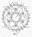
- Each of the inner peripheral portions 11b and 12b defines a plurality of radially protruding portions with mounting openings 11c and 12c, respectively. As seen in Figure 5 , the mounting openings 11c and 12c are aligned with the sprocket mounting openings 36 for receiving the fasteners 38.
- the first sprocket support member 22 together with the sprockets 13, 14 and 15 also constitutes a bicycle sprocket assembly or a sub-bicycle sprocket assembly of the bicycle sprocket assembly 10.
- the sprocket support member 22 is a one-piece, unitary member that is preferably made of a non-metallic material, such as a fiber-reinforced material, e.g. a carbon fiber-reinforced resin.
- the sprocket 15 constitutes a first sprocket
- the sprocket 14 constitutes a second sprocket
- the sprocket 13 constitutes a third sprocket.
- the third sprocket 13 is the largest sprocket of the sprockets 13, 14 and 15 that are directly mounted to the first sprocket support member 22 as an integrated bicycle sprocket assembly.
- the third sprocket 13 has the largest maximum diameter of the sprockets 13, 14 and 15 that are directly mounted to the first sprocket support member 22.
- the first sprocket 15 is the smallest sprocket of the sprockets 13, 14 and 15 that are directly mounted to the first sprocket support member 22.
- the first sprocket 15 has the smallest maximum diameter of the sprockets 13, 14 and 15 that are directly mounted to the first sprocket support member 22.
- each of the sprockets 13, 14 and 15 has a first sprocket side surface and a second sprocket side surface.
- the first sprocket side surface of each of the sprockets 13, 14 and 15 refers to the sprocket side that faces towards the smaller sprocket(s), while the second sprocket side surface of each of the sprockets 13, 14 and 15 refers to the sprocket side that faces towards the larger sprocket(s).
- the sprockets 13, 14 and 15 include outer peripheral portions 13a, 14a and 15a, respectively, that defines a plurality of teeth of the sprockets 13, 14 and 15, respectively.
- the teeth of the outer peripheral portions 13a, 14a and 15a of the sprockets 13, 14 and 15 constitute chain engaging portions.
- the sprockets 13, 14 and 15 include inner peripheral portions 13b, 14b and 15b, respectively.
- Each of the inner peripheral portions 13b, 14b and 15b defines an opening that is free of any freewheel engaging splines.
- the inner peripheral portion 15b defines a plurality of first radially protruding portions P1 with each having a mounting opening 15c.
- the inner peripheral portion 14b defines a plurality of second radially protruding portions P2 with each having a mounting opening 14c.
- the inner peripheral portion 13b defines a plurality of third radially protruding portions P3 with each having a mounting opening 13c.
- the sprockets 16, 17, 18, 19, 20 and 21 include outer peripheral portions 16a, 17a, 18a, 19a, 20a and 21a, respectively, that defines a plurality of teeth for each of the sprockets 16, 17, 18, 19, 20 and 21, respectively.
- the sprockets 16, 17, 18, 19, 20 and 21 include inner peripheral portions 16b, 17b, 18b, 19b, 20b and 21b, respectively, that each define an opening having a plurality of freewheel engaging splines.
- the inner peripheral portion 20b of the sprocket 20 is formed with an integrated spacer portion.
- the inner peripheral portion 21b of the sprocket 21 is formed with integrated spacer portion. Since the sprockets 16, 17, 18, 19, 20 and 21 can be relatively conventional sprockets, the sprockets 16, 17, 18, 19, 20 and 21 will not be discussed in further detail.
- the sprocket support member 22 supports the sprockets 13, 14 and 15.
- the sprocket support member 22 includes a first axial face ( Figure 6 ) and a second axial face ( Figure 7 ) that faces in an opposite direction with respect to the center rotational axis A of the bicycle sprocket assembly 10.
- the sprockets 14 and 15 are both disposed on the first axial face of the sprocket support member 22 without any intervening sprockets disposed between the sprockets 14 and 15.
- the sprocket 13 is disposed on the second axial face of the sprocket support member 22 without any intervening sprockets disposed between the sprockets 13 and 14.
- the sprocket support member 22 has a freewheel engaging portion 40 and a plurality of sprocket mounting portions or spider arms 42.
- the freewheel engaging portion 40 has a splined opening 44 with a plurality of freewheel engaging splines.
- the splines of the splined opening 44 are dimensioned to non-rotatably engage splines of a conventional freewheel (not shown) of a rear hub (not shown) in a relatively conventional manner.
- the splined opening 44 is configured so that the sprocket support member 22 can only fit on the freewheel (not shown) in a single orientation.
- the sprocket mounting portions 42 extend radially outwardly from the freewheel engaging portion 40.
- Each of the sprocket mounting portions 42 has a first or inner sprocket mounting opening 46a with a center axis C1 and a second or outer sprocket mounting opening 46b with a center axis C2.
- the mounting openings 15c are aligned with the sprocket mounting openings 46a for receiving the first fasteners 48a.
- the mounting openings 13c and 14c are aligned with the sprocket mounting openings 46b for receiving the second fasteners 48b.
- the sprocket mounting openings 46a is circumferentially offset from the second sprocket mounting openings 46b with respect to the center rotational axis A of the bicycle sprocket assembly 10 for each of the sprocket mounting portions 42.
- the first and second sprocket mounting openings 46a and 46b are arranged with respect to the center rotational axis A of the bicycle sprocket assembly 10 such that the deformed head portions of the first and second fasteners 48a and 48b radially overlap relative to the center rotational axis A.
- the outermost edges of the deformed head portions of the first fasteners 48a is spaced farther from the center rotational axis A than the innermost edges of the deformed head portions of the second fasteners 48b. While the deformed head portions of the first fasteners 48a radially overlap with the deformed head portions of the second fasteners 48b relative to the center rotational axis A in the illustrated embodiment, other arrangements are possible.
- each of the sprocket mounting portions 42 has a radial length L that is smaller than conventional spider arms of a conventional sprocket support member with the same number of sprockets. Also with this arrangement of the first and second sprocket mounting openings 46a and 46b, each of the sprocket mounting portions 42 has a circumferential width W that is larger than conventional spider arms of a conventional sprocket support member with the same number of sprockets.
- carbon material can be more easily used for the material of the sprocket support member 22 than for conventional spider arms, because such short and wide mounting portions are preferable for carbon conventional spider arms.
- Each of the first sprocket mounting openings 46a receives a first or inner fastener 48a for fixedly mounting the radially protruding portions P1 of the sprocket 15 to the sprocket support member 22 via the mounting openings 15c of the sprocket 15.
- the radially protruding portions P1 of the sprocket 15 are fixed to corresponding ones of the sprocket mounting portions 42 of the sprocket support member 22 at the sprocket mounting openings 46a by the fasteners 48a.
- the fasteners 48a are rivets. In this way, the sprocket 15 is fixed to the sprocket support member 22 by the fasteners 48a, which do not directly connect any other spacers or sprockets to the sprocket support member 22.
- Each of the second sprocket mounting openings 46b receives a second or outer fastener 48b for fixedly mounting the sprockets 13 and 14 to the sprocket support member 22.
- the radially protruding portions P3 of the sprocket 13 and the radially protruding portions P2 of the sprocket 14 are fixed to corresponding ones of the sprocket mounting portions 42 of the sprocket support member 22 at the second sprocket mounting openings 46b by a common one of the fasteners 48b in each of the second sprocket mounting openings 46b of the sprocket mounting portions 42.
- the fasteners 48b are rivets.
- the sprockets 13 and 14 are fixed to the sprocket support member 22 by the fasteners 48b (e.g., at least one common fastener), which do not directly connect any other spacers or sprockets to the sprocket support member 22.
- the fasteners 48b e.g., at least one common fastener
- each of the sprocket mounting portions 42 has a step shaped configuration for axially spacing the sprockets 14 and 15.
- each of the sprocket mounting portions 42 has an outwardly facing surface 50 extending axially between a first sprocket mounting surface 52 and a second sprocket mounting surface 54.
- the sprocket 15 directly contacts the first sprocket mounting surface 52 and the sprocket 14 directly contacts the second sprocket mounting surface 54 with the sprockets 14 and 15 being axially spaced apart by the outwardly facing surface 50.
- the radially outermost edges of the first sprocket mounting openings 46a are spaced from the center rotational axis A of the bicycle sprocket assembly 10 by a first radial distance R1.
- the radially innermost points of the radially protruding portions P2 of the sprocket 14 are spaced from the center rotational axis A of the bicycle sprocket assembly 10 by a second radial distance R2.
- the second radial distance R2 is smaller than the first radial distance R1.
- the radially protruding portions P2 of the sprocket 14 radially overlap with the radially outermost edges of the first sprocket mounting openings 46a relative to the center rotational axis A.
- the overall radial dimension of the sprocket 14 can be smaller than a conventional sprocket having the same total number of teeth.
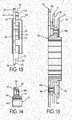
- an alternative bicycle sprocket assembly is illustrated in a cross section in accordance with another illustrated embodiment.
- the alternative bicycle sprocket assembly includes a sprocket support member 122 that supports the sprockets 13, 14 and 15 in the same manner as the sprocket support member 22.
- the only difference between the sprocket support member 22 and the sprocket support member 122 is that the sprocket support member 122 is made of a metallic material such as aluminum or iron instead of a fiber-reinforced material.
- description of the sprocket support member 22 applies to the sprocket support member 122.
- the term “smaller sprocket” refers to a sprocket having a smaller diameter with respect to the claimed sprocket and the term “larger sprocket” refers to a sprocket having a larger diameter with respect to the sprocket in question.
- the term "smaller sprocket facing side surface” refers to a side surface of the sprocket in question that faces a sprocket having a smaller diameter with respect to the sprocket in question and the term “larger sprocket facing side surface” refers to a side surface of the sprocket in question that faces a sprocket having a larger diameter with respect to the sprocket in question.
- the term “adjacent sprocket” refers to an immediate adjacent sprocket to a sprocket in question with no intervening sprockets located between the "adjacent sprocket" and the sprocket in question.
- fixed or “secured”, as used herein, encompass configurations in which an element is directly secured to another element by affixing the element directly to the other element; configurations in which an element is indirectly secured to another element by affixing the element to intermediate member(s) which in turn are affixed to the other element; and configurations in which one element is integral with another element, i.e. one element is essentially part of the other element.
- This definition also applies to words of similar meaning, for example the terms “joined” and “attached” and their derivatives.
- terms of degree such as “substantially”, “about” and “approximately” as used herein mean a reasonable amount of deviation of the modified term such that the end result is not significantly changed.
Landscapes
- Engineering & Computer Science (AREA)
- Chemical & Material Sciences (AREA)
- Combustion & Propulsion (AREA)
- Transportation (AREA)
- Mechanical Engineering (AREA)
- Gears, Cams (AREA)
- Axle Suspensions And Sidecars For Cycles (AREA)
Claims (8)
- Fahrrad-Kettenradanordnung (10), umfassend:ein erstes Kettenrad (15) mit einem äußeren Umfangsabschnitt (15a), der eine Vielzahl von ersten Zähnen definiert, und einem inneren Umfangsabschnitt (15b), der eine erste Öffnung definiert, die frei von Freilaufkeilverzahnungen ist, wobei der innere Umfangsabschnitt des ersten Kettenrades eine Vielzahl von ersten radial vorstehenden Abschnitten aufweist;ein zweites Kettenrad (14) mit einem äußeren Umfangsabschnitt (14a), der eine Vielzahl von zweiten Zähnen definiert, und einem inneren Umfangsabschnitt (14b), der eine zweite Öffnung definiert, die frei von Freilaufkeilverzahnungen ist, wobei der innere Umfangsabschnitt des zweiten Kettenrades eine Vielzahl von zweiten radial vorstehenden Abschnitten aufweist, wobei eine Gesamtzahl der zweiten Zähne größer als eine Gesamtzahl der ersten Zähne ist; undein Kettenradstützelement (22; 122) mit einem Freilaufeingriffsabschnitt (40) und einer Vielzahl von Kettenradmontageabschnitten (42), die sich radial nach außen von dem Freilaufeingriffsabschnitt erstrecken, wobei jeder der Kettenradmontageabschnitte (42) eine erste Kettenradmontageöffnung (46a) und eine zweite Kettenradmontageöffnung (46b) aufweist,wobei einer der ersten radial vorstehenden Abschnitte des ersten Kettenrades (15) an dem Kettenradstützelement an der ersten Kettenradmontageöffnung (46a) befestigt ist, und einer der zweiten radial vorstehenden Abschnitte des zweiten Kettenrades (14) an dem Kettenradstützelement an der zweiten Kettenradmontageöffnung (46b) befestigt ist,wobei die erste Kettenradmontageöffnung (46a) in Umfangsrichtung von der zweiten Kettenradmontageöffnung (46b) in Bezug auf eine mittlere Drehachse der Fahrrad-Kettenanordnung versetzt ist,wobei der radial innerste Rand des zweiten radial vorstehenden Abschnitts (P2) von der mittleren Drehachse (A) der Fahrrad-Kettenanordnung um einen Radialabstand (R2) beabstandet ist, der kleiner ist als ein Radialabstand (R1) des radial äußersten Randes der ersten Kettenradmontageöffnungen (46a) in Bezug auf die mittlere Drehachse der Fahrradkettenradanordnung,dadurch gekennzeichnet, dassdas Kettenradstützelement ein einteiliges, einheitliches Element ist,wobei das Kettenradstützelement eine erste axiale Fläche und eine zweite axiale Fläche aufweist, die in eine entgegengesetzten Richtung in Bezug auf die mittlere Drehachse (A) der Fahrrad-Kettenanordnung weist, wobei die ersten und zweiten Kettenräder beide auf der ersten axialen Fläche des Kettenradstützelements (22) angeordnet sind, ohne dass dazwischenliegende Kettenräder zwischen den ersten und zweiten Kettenrädern angeordnet sind,die Fahrrad-Kettenanordnung (10) ferner ein drittes Kettenrad (13) mit einem äußeren Umfangsabschnitt (13a) umfasst, der eine Vielzahl von dritten Zähnen definiert, undeinen inneren Umfangsabschnitt (13b), der eine dritte Öffnung definiert, die frei von Freilaufkeilverzahnungen ist, und das dritte Kettenrad auf der zweiten axialen Fläche des Kettenradträgerelements angeordnet ist, ohne dass dazwischenliegende Kettenräder zwischen dem zweiten und dritten Kettenrädern angeordnet sind.
- Fahrrad-Kettenradanordnung nach Anspruch 1, bei welcher jede der zweiten Kettenradmontageöffnungen einen radial innersten Rand aufweist, der von der mittleren Drehachse der Fahrrad-Kettenradanordnung durch einen Radialabstand beabstandet ist, der kleiner ist als ein Radialabstand des radial äußersten Randes der ersten Kettenradmontageöffnungen in Bezug auf die mittlere Drehachse der Fahrradkettenradanordnung.
- Fahrrad-Kettenradanordnung nach Anspruch 1 oder 2, bei welcher die zweiten und dritten Kettenräder (13, 14) am Kettenradstützelement (22) an den zweiten Kettenradmontageöffnungen (46b) durch ein gemeinsames Befestigungselement (48b) in jedem der Kettenradmontageabschnitte befestigt sind.
- Die Fahrrad-Kettenradanordnung nach einem der Ansprüche 1 bis 3, bei welcher das Kettenradstützelement (22) aus einem nichtmetallischen Material hergestellt ist.
- Die Fahrrad-Kettenradanordnung nach Anspruch 4, bei welcher das Kettenradstützelement (22) aus einem faserverstärkten Material hergestellt ist.
- Fahrrad-Kettenanordnung nach einem der Ansprüche 1 bis 3, bei welcher das Kettenradstützelement (122) aus einem metallischen Material hergestellt ist.
- Fahrrad-Kettenanordnung nach Anspruch 6, bei welcher das Kettenradstützelement (122) aus Aluminium hergestellt ist.
- Fahrrad-Kettenanordnung nach Anspruch 6, bei welcher das Kettenradstützelement (122) aus Eisen hergestellt ist.
Applications Claiming Priority (1)
| Application Number | Priority Date | Filing Date | Title |
|---|---|---|---|
| US13/197,880 US8956254B2 (en) | 2011-08-04 | 2011-08-04 | Bicycle sprocket assembly |
Publications (2)
| Publication Number | Publication Date |
|---|---|
| EP2554468A1 EP2554468A1 (de) | 2013-02-06 |
| EP2554468B1 true EP2554468B1 (de) | 2020-02-12 |
Family
ID=45406477
Family Applications (1)
| Application Number | Title | Priority Date | Filing Date |
|---|---|---|---|
| EP11194722.2A Active EP2554468B1 (de) | 2011-08-04 | 2011-12-21 | Fahrradkettenradbaugruppe |
Country Status (4)
| Country | Link |
|---|---|
| US (1) | US8956254B2 (de) |
| EP (1) | EP2554468B1 (de) |
| CN (1) | CN102910248B (de) |
| TW (1) | TWI507324B (de) |
Families Citing this family (43)
| Publication number | Priority date | Publication date | Assignee | Title |
|---|---|---|---|---|
| US9415835B2 (en) * | 2014-01-24 | 2016-08-16 | Shimano Inc. | Rotatable annular bicycle component and bicycle rear sprocket |
| US9446815B2 (en) * | 2014-09-19 | 2016-09-20 | Vp Components Co., Ltd | Chain wheel assembly and chain wheel device using it |
| AU358118S (en) * | 2014-09-25 | 2014-10-13 | Calcino Corp Pty Ltd | A sprocket |
| US9511819B1 (en) | 2015-05-25 | 2016-12-06 | Shimano Inc. | Bicycle rear sprocket assembly |
| CN106275229A (zh) * | 2015-06-09 | 2017-01-04 | 乔绅股份有限公司 | 花毂与飞轮组合结构 |
| EP3109062A1 (de) * | 2015-06-25 | 2016-12-28 | Chosen Co., Ltd. | Anordnung von nabe und freilauf |
| US10407126B2 (en) * | 2015-08-28 | 2019-09-10 | Shimano Inc. | Bicycle rear sprocket assembly and bicycle rear sprocket |
| US10005520B2 (en) * | 2016-02-12 | 2018-06-26 | Shimano Inc. | Bicycle driving system and a multiple rear sprocket assembly thereof |
| US9994285B2 (en) * | 2016-06-15 | 2018-06-12 | Shimano Inc. | Multiple bicycle sprocket assembly |
| US10093388B2 (en) * | 2016-06-28 | 2018-10-09 | Shimano Inc. | Bicycle rear sprocket assembly |
| US10053187B2 (en) * | 2016-07-07 | 2018-08-21 | Shimano Inc. | Bicycle rear sprocket assembly and bicycle rear sprocket |
| US10112681B2 (en) * | 2016-07-21 | 2018-10-30 | Shimano Inc. | Bicycle sprocket supporting member and bicycle sprocket assembly |
| US9868491B1 (en) * | 2016-07-21 | 2018-01-16 | Shimano Inc. | Bicycle sprocket assembly |
| ES2656783B1 (es) * | 2016-08-30 | 2018-12-11 | Rotor Componentes Tecnológicos,S.L. | Conjunto de piñones de bicicleta |
| US10138991B2 (en) * | 2016-09-14 | 2018-11-27 | Shimano Inc. | Bicycle sprocket |
| US10377445B2 (en) * | 2016-09-20 | 2019-08-13 | Shimano Inc. | Bicycle front sprocket assembly |
| US11364971B2 (en) * | 2017-07-31 | 2022-06-21 | Shimano Inc. | Bicycle sprocket assembly and bicycle drive train |
| US10625820B2 (en) * | 2018-01-24 | 2020-04-21 | Shimano Inc. | Bicycle rear sprocket assembly |
| TWI868953B (zh) * | 2017-05-30 | 2025-01-01 | 日商島野股份有限公司 | 自行車後輪轂總成及鏈輪支撐主體 |
| US10550925B2 (en) * | 2017-06-02 | 2020-02-04 | Shimano Inc. | Bicycle sprocket |
| US10926836B2 (en) * | 2017-08-24 | 2021-02-23 | Shimano Inc. | Bicycle rear sprocket assembly |
| US10668980B2 (en) * | 2017-08-24 | 2020-06-02 | Shimano Inc. | Bicycle rear sprocket assembly |
| DE102017008074A1 (de) * | 2017-08-28 | 2019-02-28 | Sram Deutschland Gmbh | Kettenradträger und Mehrfach-Kettenradanordnung |
| IT201700115411A1 (it) * | 2017-10-13 | 2019-04-13 | Campagnolo Srl | Corpetto per mozzo di ruota posteriore di bicicletta e pacco pignoni atto ad essere montato sul mozzo mediante tale corpetto |
| IT201700115407A1 (it) | 2017-10-13 | 2019-04-13 | Campagnolo Srl | Pacco pignoni e corpetto per il suo montaggio su un mozzo di ruota posteriore di bicicletta |
| US10618588B2 (en) | 2017-12-13 | 2020-04-14 | Gates Corporation | Sprocket guard |
| US10830329B2 (en) * | 2018-03-08 | 2020-11-10 | Shimano Inc. | Bicycle sprocket |
| US11338886B2 (en) * | 2018-05-24 | 2022-05-24 | Shimano Inc. | Bicycle multiple sprocket and bicycle sprocket |
| US11072203B2 (en) * | 2018-08-22 | 2021-07-27 | Sram, Llc | Bicycle sprocket assembly |
| US11008065B2 (en) * | 2018-11-07 | 2021-05-18 | Shimano Inc. | Bicycle sprocket arrangement |
| US11338887B2 (en) * | 2019-02-21 | 2022-05-24 | Shimano Inc. | Bicycle rear sprocket |
| TWI839545B (zh) | 2019-07-30 | 2024-04-21 | 義大利商坎帕克諾羅公司 | 用於自行車後輪的變速盤和子組件 |
| IT201900013287A1 (it) * | 2019-07-30 | 2021-01-30 | Campagnolo Srl | Adattatore per un corpo porta-pignoni per una ruota posteriore di bicicletta |
| EP3960606A1 (de) * | 2020-09-01 | 2022-03-02 | SRAM Deutschland GmbH | Mehrfachritzel-baugruppe und hinterradbaugruppe für ein fahrrad mit kettenschaltung |
| US11529827B2 (en) * | 2020-12-10 | 2022-12-20 | Tien Hsin Industries Co., Ltd. | Transmission assembly of a bicycle |
| US11858588B2 (en) * | 2021-04-29 | 2024-01-02 | Shimano Inc. | Rear sprocket assembly and lock device |
| US11603166B2 (en) * | 2021-04-29 | 2023-03-14 | Shimano Inc. | Rear sprocket assembly and lock device |
| US11767080B1 (en) * | 2022-07-15 | 2023-09-26 | Shimano Inc. | Rear sprocket assembly |
| US12187384B2 (en) * | 2022-08-30 | 2025-01-07 | Shimano Inc. | Rear sprocket |
| CN218408333U (zh) * | 2022-11-02 | 2023-01-31 | 深圳市壹马赫科技有限公司 | 一种新型自行车飞轮 |
| EP4389577A3 (de) * | 2022-12-23 | 2024-10-23 | SRAM Deutschland GmbH | Mehrfach-ritzelanordnung und baukastensystem für mehrfach-ritzelanordnungen |
| US12252216B2 (en) | 2023-06-27 | 2025-03-18 | Shimano Inc. | Rear sprocket assembly |
| TWI863613B (zh) * | 2023-10-06 | 2024-11-21 | 日馳企業股份有限公司 | 自行車傳動裝置 |
Family Cites Families (13)
| Publication number | Priority date | Publication date | Assignee | Title |
|---|---|---|---|---|
| IT1245431B (it) * | 1991-03-04 | 1994-09-20 | Campagnolo Srl | Gruppo pedivella-ingranaggi per una bicicletta |
| US5954604A (en) | 1996-11-21 | 1999-09-21 | Shimano, Inc. | Multiple sprocket assembly for a bicycle |
| IT1289715B1 (it) * | 1996-12-05 | 1998-10-16 | Campagnolo Srl | Gruppo sopporto pignoni per una bicicletta |
| DE19937212A1 (de) | 1999-08-06 | 2001-02-15 | Sram De Gmbh | Ritzelkassette für eine Kettenschaltung eines Fahrrades |
| EP1407962A1 (de) * | 2002-10-11 | 2004-04-14 | Campagnolo Srl | Tragstruktur für Fahrradzahnkränze |
| DE10342638B4 (de) | 2003-09-16 | 2017-02-23 | Sram Deutschland Gmbh | Ritzeleinheit für eine Kettenschaltung eines Fahrrades |
| TWM246115U (en) * | 2003-11-20 | 2004-10-11 | Joy Ind Co Ltd | Ratcheted sleeve for bicycle |
| JP4531050B2 (ja) * | 2004-07-08 | 2010-08-25 | ヤマハ発動機株式会社 | パワーユニット及び該パワーユニットを備えた鞍乗型車両 |
| JP4682579B2 (ja) * | 2004-10-05 | 2011-05-11 | スズキ株式会社 | 自動二輪車のパワーユニット |
| US7585240B2 (en) | 2005-02-03 | 2009-09-08 | Shimano Inc. | Bicycle sprocket assembly |
| US20080004143A1 (en) | 2006-06-16 | 2008-01-03 | Shimano Inc. | Bicycle sprocket assembly |
| TWM304484U (en) * | 2006-07-19 | 2007-01-11 | Chosen Co Ltd | Structure of ratchet wheel of a bicycle hub |
| ITMI20071661A1 (it) * | 2007-08-09 | 2009-02-10 | Campagnolo Srl | Assieme di ruote dentate per una bicicletta |
-
2011
- 2011-08-04 US US13/197,880 patent/US8956254B2/en active Active
- 2011-12-05 TW TW100144673A patent/TWI507324B/zh active
- 2011-12-21 EP EP11194722.2A patent/EP2554468B1/de active Active
-
2012
- 2012-04-09 CN CN201210102144.9A patent/CN102910248B/zh active Active
Non-Patent Citations (1)
| Title |
|---|
| None * |
Also Published As
| Publication number | Publication date |
|---|---|
| TW201307150A (zh) | 2013-02-16 |
| US8956254B2 (en) | 2015-02-17 |
| CN102910248B (zh) | 2014-11-26 |
| TWI507324B (zh) | 2015-11-11 |
| CN102910248A (zh) | 2013-02-06 |
| US20130035183A1 (en) | 2013-02-07 |
| EP2554468A1 (de) | 2013-02-06 |
Similar Documents
| Publication | Publication Date | Title |
|---|---|---|
| EP2554468B1 (de) | Fahrradkettenradbaugruppe | |
| EP2495161B1 (de) | Fahrradkettenradbaugruppe | |
| US8905878B2 (en) | Bicycle sprocket assembly | |
| US10112681B2 (en) | Bicycle sprocket supporting member and bicycle sprocket assembly | |
| US9868491B1 (en) | Bicycle sprocket assembly | |
| US9994285B2 (en) | Multiple bicycle sprocket assembly | |
| US10773772B2 (en) | Bicycle sprocket assembly | |
| EP1995166B1 (de) | Fahrradkettensatz mit Kettenschutz | |
| US10377445B2 (en) | Bicycle front sprocket assembly | |
| CN100439194C (zh) | 自行车链轮组合件 | |
| US9297450B2 (en) | Bicycle rear sprocket | |
| US6443865B1 (en) | Bicycle front chainwheel assembly | |
| US10315727B2 (en) | Bicycle rear sprocket assembly | |
| US20080058144A1 (en) | Bicycle sprocket assembly | |
| US10618597B2 (en) | Bicycle sprocket assembly | |
| US10717495B2 (en) | Bicycle sprocket |
Legal Events
| Date | Code | Title | Description |
|---|---|---|---|
| PUAI | Public reference made under article 153(3) epc to a published international application that has entered the european phase |
Free format text: ORIGINAL CODE: 0009012 |
|
| AK | Designated contracting states |
Kind code of ref document: A1 Designated state(s): AL AT BE BG CH CY CZ DE DK EE ES FI FR GB GR HR HU IE IS IT LI LT LU LV MC MK MT NL NO PL PT RO RS SE SI SK SM TR |
|
| AX | Request for extension of the european patent |
Extension state: BA ME |
|
| 17P | Request for examination filed |
Effective date: 20130806 |
|
| RBV | Designated contracting states (corrected) |
Designated state(s): AL AT BE BG CH CY CZ DE DK EE ES FI FR GB GR HR HU IE IS IT LI LT LU LV MC MK MT NL NO PL PT RO RS SE SI SK SM TR |
|
| STAA | Information on the status of an ep patent application or granted ep patent |
Free format text: STATUS: EXAMINATION IS IN PROGRESS |
|
| 17Q | First examination report despatched |
Effective date: 20170706 |
|
| GRAP | Despatch of communication of intention to grant a patent |
Free format text: ORIGINAL CODE: EPIDOSNIGR1 |
|
| STAA | Information on the status of an ep patent application or granted ep patent |
Free format text: STATUS: GRANT OF PATENT IS INTENDED |
|
| INTG | Intention to grant announced |
Effective date: 20190716 |
|
| RAP1 | Party data changed (applicant data changed or rights of an application transferred) |
Owner name: SHIMANO, INC. |
|
| GRAS | Grant fee paid |
Free format text: ORIGINAL CODE: EPIDOSNIGR3 |
|
| GRAA | (expected) grant |
Free format text: ORIGINAL CODE: 0009210 |
|
| STAA | Information on the status of an ep patent application or granted ep patent |
Free format text: STATUS: THE PATENT HAS BEEN GRANTED |
|
| AK | Designated contracting states |
Kind code of ref document: B1 Designated state(s): AL AT BE BG CH CY CZ DE DK EE ES FI FR GB GR HR HU IE IS IT LI LT LU LV MC MK MT NL NO PL PT RO RS SE SI SK SM TR |
|
| REG | Reference to a national code |
Ref country code: GB Ref legal event code: FG4D |
|
| REG | Reference to a national code |
Ref country code: CH Ref legal event code: EP |
|
| REG | Reference to a national code |
Ref country code: AT Ref legal event code: REF Ref document number: 1231747 Country of ref document: AT Kind code of ref document: T Effective date: 20200215 |
|
| REG | Reference to a national code |
Ref country code: IE Ref legal event code: FG4D |
|
| REG | Reference to a national code |
Ref country code: DE Ref legal event code: R096 Ref document number: 602011064909 Country of ref document: DE |
|
| PG25 | Lapsed in a contracting state [announced via postgrant information from national office to epo] |
Ref country code: RS Free format text: LAPSE BECAUSE OF FAILURE TO SUBMIT A TRANSLATION OF THE DESCRIPTION OR TO PAY THE FEE WITHIN THE PRESCRIBED TIME-LIMIT Effective date: 20200212 Ref country code: NO Free format text: LAPSE BECAUSE OF FAILURE TO SUBMIT A TRANSLATION OF THE DESCRIPTION OR TO PAY THE FEE WITHIN THE PRESCRIBED TIME-LIMIT Effective date: 20200512 Ref country code: FI Free format text: LAPSE BECAUSE OF FAILURE TO SUBMIT A TRANSLATION OF THE DESCRIPTION OR TO PAY THE FEE WITHIN THE PRESCRIBED TIME-LIMIT Effective date: 20200212 |
|
| REG | Reference to a national code |
Ref country code: LT Ref legal event code: MG4D |
|
| REG | Reference to a national code |
Ref country code: NL Ref legal event code: MP Effective date: 20200212 |
|
| PG25 | Lapsed in a contracting state [announced via postgrant information from national office to epo] |
Ref country code: LV Free format text: LAPSE BECAUSE OF FAILURE TO SUBMIT A TRANSLATION OF THE DESCRIPTION OR TO PAY THE FEE WITHIN THE PRESCRIBED TIME-LIMIT Effective date: 20200212 Ref country code: SE Free format text: LAPSE BECAUSE OF FAILURE TO SUBMIT A TRANSLATION OF THE DESCRIPTION OR TO PAY THE FEE WITHIN THE PRESCRIBED TIME-LIMIT Effective date: 20200212 Ref country code: IS Free format text: LAPSE BECAUSE OF FAILURE TO SUBMIT A TRANSLATION OF THE DESCRIPTION OR TO PAY THE FEE WITHIN THE PRESCRIBED TIME-LIMIT Effective date: 20200612 Ref country code: HR Free format text: LAPSE BECAUSE OF FAILURE TO SUBMIT A TRANSLATION OF THE DESCRIPTION OR TO PAY THE FEE WITHIN THE PRESCRIBED TIME-LIMIT Effective date: 20200212 Ref country code: BG Free format text: LAPSE BECAUSE OF FAILURE TO SUBMIT A TRANSLATION OF THE DESCRIPTION OR TO PAY THE FEE WITHIN THE PRESCRIBED TIME-LIMIT Effective date: 20200512 Ref country code: GR Free format text: LAPSE BECAUSE OF FAILURE TO SUBMIT A TRANSLATION OF THE DESCRIPTION OR TO PAY THE FEE WITHIN THE PRESCRIBED TIME-LIMIT Effective date: 20200513 |
|
| PG25 | Lapsed in a contracting state [announced via postgrant information from national office to epo] |
Ref country code: NL Free format text: LAPSE BECAUSE OF FAILURE TO SUBMIT A TRANSLATION OF THE DESCRIPTION OR TO PAY THE FEE WITHIN THE PRESCRIBED TIME-LIMIT Effective date: 20200212 |
|
| REG | Reference to a national code |
Ref country code: DE Ref legal event code: R082 Ref document number: 602011064909 Country of ref document: DE Representative=s name: SONNENBERG HARRISON PARTNERSCHAFT MBB PATENT- , DE Ref country code: DE Ref legal event code: R082 Ref document number: 602011064909 Country of ref document: DE Representative=s name: SONNENBERG HARRISON PARTNERSCHAFT MBB, DE |
|
| PG25 | Lapsed in a contracting state [announced via postgrant information from national office to epo] |
Ref country code: EE Free format text: LAPSE BECAUSE OF FAILURE TO SUBMIT A TRANSLATION OF THE DESCRIPTION OR TO PAY THE FEE WITHIN THE PRESCRIBED TIME-LIMIT Effective date: 20200212 Ref country code: SM Free format text: LAPSE BECAUSE OF FAILURE TO SUBMIT A TRANSLATION OF THE DESCRIPTION OR TO PAY THE FEE WITHIN THE PRESCRIBED TIME-LIMIT Effective date: 20200212 Ref country code: DK Free format text: LAPSE BECAUSE OF FAILURE TO SUBMIT A TRANSLATION OF THE DESCRIPTION OR TO PAY THE FEE WITHIN THE PRESCRIBED TIME-LIMIT Effective date: 20200212 Ref country code: RO Free format text: LAPSE BECAUSE OF FAILURE TO SUBMIT A TRANSLATION OF THE DESCRIPTION OR TO PAY THE FEE WITHIN THE PRESCRIBED TIME-LIMIT Effective date: 20200212 Ref country code: SK Free format text: LAPSE BECAUSE OF FAILURE TO SUBMIT A TRANSLATION OF THE DESCRIPTION OR TO PAY THE FEE WITHIN THE PRESCRIBED TIME-LIMIT Effective date: 20200212 Ref country code: PT Free format text: LAPSE BECAUSE OF FAILURE TO SUBMIT A TRANSLATION OF THE DESCRIPTION OR TO PAY THE FEE WITHIN THE PRESCRIBED TIME-LIMIT Effective date: 20200705 Ref country code: LT Free format text: LAPSE BECAUSE OF FAILURE TO SUBMIT A TRANSLATION OF THE DESCRIPTION OR TO PAY THE FEE WITHIN THE PRESCRIBED TIME-LIMIT Effective date: 20200212 Ref country code: CZ Free format text: LAPSE BECAUSE OF FAILURE TO SUBMIT A TRANSLATION OF THE DESCRIPTION OR TO PAY THE FEE WITHIN THE PRESCRIBED TIME-LIMIT Effective date: 20200212 Ref country code: ES Free format text: LAPSE BECAUSE OF FAILURE TO SUBMIT A TRANSLATION OF THE DESCRIPTION OR TO PAY THE FEE WITHIN THE PRESCRIBED TIME-LIMIT Effective date: 20200212 |
|
| REG | Reference to a national code |
Ref country code: DE Ref legal event code: R097 Ref document number: 602011064909 Country of ref document: DE |
|
| REG | Reference to a national code |
Ref country code: AT Ref legal event code: MK05 Ref document number: 1231747 Country of ref document: AT Kind code of ref document: T Effective date: 20200212 |
|
| PLBE | No opposition filed within time limit |
Free format text: ORIGINAL CODE: 0009261 |
|
| STAA | Information on the status of an ep patent application or granted ep patent |
Free format text: STATUS: NO OPPOSITION FILED WITHIN TIME LIMIT |
|
| 26N | No opposition filed |
Effective date: 20201113 |
|
| PG25 | Lapsed in a contracting state [announced via postgrant information from national office to epo] |
Ref country code: AT Free format text: LAPSE BECAUSE OF FAILURE TO SUBMIT A TRANSLATION OF THE DESCRIPTION OR TO PAY THE FEE WITHIN THE PRESCRIBED TIME-LIMIT Effective date: 20200212 Ref country code: IT Free format text: LAPSE BECAUSE OF FAILURE TO SUBMIT A TRANSLATION OF THE DESCRIPTION OR TO PAY THE FEE WITHIN THE PRESCRIBED TIME-LIMIT Effective date: 20200212 |
|
| PG25 | Lapsed in a contracting state [announced via postgrant information from national office to epo] |
Ref country code: SI Free format text: LAPSE BECAUSE OF FAILURE TO SUBMIT A TRANSLATION OF THE DESCRIPTION OR TO PAY THE FEE WITHIN THE PRESCRIBED TIME-LIMIT Effective date: 20200212 Ref country code: PL Free format text: LAPSE BECAUSE OF FAILURE TO SUBMIT A TRANSLATION OF THE DESCRIPTION OR TO PAY THE FEE WITHIN THE PRESCRIBED TIME-LIMIT Effective date: 20200212 |
|
| REG | Reference to a national code |
Ref country code: CH Ref legal event code: PL |
|
| GBPC | Gb: european patent ceased through non-payment of renewal fee |
Effective date: 20201221 |
|
| PG25 | Lapsed in a contracting state [announced via postgrant information from national office to epo] |
Ref country code: MC Free format text: LAPSE BECAUSE OF FAILURE TO SUBMIT A TRANSLATION OF THE DESCRIPTION OR TO PAY THE FEE WITHIN THE PRESCRIBED TIME-LIMIT Effective date: 20200212 |
|
| REG | Reference to a national code |
Ref country code: BE Ref legal event code: MM Effective date: 20201231 |
|
| PG25 | Lapsed in a contracting state [announced via postgrant information from national office to epo] |
Ref country code: IE Free format text: LAPSE BECAUSE OF NON-PAYMENT OF DUE FEES Effective date: 20201221 Ref country code: LU Free format text: LAPSE BECAUSE OF NON-PAYMENT OF DUE FEES Effective date: 20201221 Ref country code: FR Free format text: LAPSE BECAUSE OF NON-PAYMENT OF DUE FEES Effective date: 20201231 |
|
| PG25 | Lapsed in a contracting state [announced via postgrant information from national office to epo] |
Ref country code: LI Free format text: LAPSE BECAUSE OF NON-PAYMENT OF DUE FEES Effective date: 20201231 Ref country code: CH Free format text: LAPSE BECAUSE OF NON-PAYMENT OF DUE FEES Effective date: 20201231 Ref country code: GB Free format text: LAPSE BECAUSE OF NON-PAYMENT OF DUE FEES Effective date: 20201221 |
|
| PG25 | Lapsed in a contracting state [announced via postgrant information from national office to epo] |
Ref country code: TR Free format text: LAPSE BECAUSE OF FAILURE TO SUBMIT A TRANSLATION OF THE DESCRIPTION OR TO PAY THE FEE WITHIN THE PRESCRIBED TIME-LIMIT Effective date: 20200212 Ref country code: MT Free format text: LAPSE BECAUSE OF FAILURE TO SUBMIT A TRANSLATION OF THE DESCRIPTION OR TO PAY THE FEE WITHIN THE PRESCRIBED TIME-LIMIT Effective date: 20200212 Ref country code: CY Free format text: LAPSE BECAUSE OF FAILURE TO SUBMIT A TRANSLATION OF THE DESCRIPTION OR TO PAY THE FEE WITHIN THE PRESCRIBED TIME-LIMIT Effective date: 20200212 |
|
| PG25 | Lapsed in a contracting state [announced via postgrant information from national office to epo] |
Ref country code: MK Free format text: LAPSE BECAUSE OF FAILURE TO SUBMIT A TRANSLATION OF THE DESCRIPTION OR TO PAY THE FEE WITHIN THE PRESCRIBED TIME-LIMIT Effective date: 20200212 Ref country code: AL Free format text: LAPSE BECAUSE OF FAILURE TO SUBMIT A TRANSLATION OF THE DESCRIPTION OR TO PAY THE FEE WITHIN THE PRESCRIBED TIME-LIMIT Effective date: 20200212 |
|
| PG25 | Lapsed in a contracting state [announced via postgrant information from national office to epo] |
Ref country code: BE Free format text: LAPSE BECAUSE OF NON-PAYMENT OF DUE FEES Effective date: 20201231 |
|
| P01 | Opt-out of the competence of the unified patent court (upc) registered |
Effective date: 20230424 |
|
| PGFP | Annual fee paid to national office [announced via postgrant information from national office to epo] |
Ref country code: DE Payment date: 20251028 Year of fee payment: 15 |