EP2554477A2 - Aéronef avec une structure pour diviser un espace - Google Patents
Aéronef avec une structure pour diviser un espace Download PDFInfo
- Publication number
- EP2554477A2 EP2554477A2 EP12007414A EP12007414A EP2554477A2 EP 2554477 A2 EP2554477 A2 EP 2554477A2 EP 12007414 A EP12007414 A EP 12007414A EP 12007414 A EP12007414 A EP 12007414A EP 2554477 A2 EP2554477 A2 EP 2554477A2
- Authority
- EP
- European Patent Office
- Prior art keywords
- wall structure
- air chamber
- aircraft according
- ceiling
- aircraft
- Prior art date
- Legal status (The legal status is an assumption and is not a legal conclusion. Google has not performed a legal analysis and makes no representation as to the accuracy of the status listed.)
- Granted
Links
- 238000000638 solvent extraction Methods 0.000 title 1
- 239000000463 material Substances 0.000 claims abstract description 10
- 230000000087 stabilizing effect Effects 0.000 claims abstract description 5
- 238000005192 partition Methods 0.000 claims description 2
- 238000000926 separation method Methods 0.000 claims description 2
- 238000010276 construction Methods 0.000 description 6
- 238000009413 insulation Methods 0.000 description 4
- 238000013459 approach Methods 0.000 description 2
- 230000000694 effects Effects 0.000 description 2
- 239000006260 foam Substances 0.000 description 2
- QFLWZFQWSBQYPS-AWRAUJHKSA-N (3S)-3-[[(2S)-2-[[(2S)-2-[5-[(3aS,6aR)-2-oxo-1,3,3a,4,6,6a-hexahydrothieno[3,4-d]imidazol-4-yl]pentanoylamino]-3-methylbutanoyl]amino]-3-(4-hydroxyphenyl)propanoyl]amino]-4-[1-bis(4-chlorophenoxy)phosphorylbutylamino]-4-oxobutanoic acid Chemical compound CCCC(NC(=O)[C@H](CC(O)=O)NC(=O)[C@H](Cc1ccc(O)cc1)NC(=O)[C@@H](NC(=O)CCCCC1SC[C@@H]2NC(=O)N[C@H]12)C(C)C)P(=O)(Oc1ccc(Cl)cc1)Oc1ccc(Cl)cc1 QFLWZFQWSBQYPS-AWRAUJHKSA-N 0.000 description 1
- 230000002411 adverse Effects 0.000 description 1
- 230000008878 coupling Effects 0.000 description 1
- 238000010168 coupling process Methods 0.000 description 1
- 238000005859 coupling reaction Methods 0.000 description 1
- 230000007423 decrease Effects 0.000 description 1
- 238000010616 electrical installation Methods 0.000 description 1
- 230000002349 favourable effect Effects 0.000 description 1
- 230000010006 flight Effects 0.000 description 1
- 238000005286 illumination Methods 0.000 description 1
- 238000009434 installation Methods 0.000 description 1
- 239000000203 mixture Substances 0.000 description 1
- 230000001105 regulatory effect Effects 0.000 description 1
- 239000002356 single layer Substances 0.000 description 1
- 239000007787 solid Substances 0.000 description 1
- 239000011343 solid material Substances 0.000 description 1
- 230000003068 static effect Effects 0.000 description 1
- 230000007704 transition Effects 0.000 description 1
Images
Classifications
-
- B—PERFORMING OPERATIONS; TRANSPORTING
- B64—AIRCRAFT; AVIATION; COSMONAUTICS
- B64D—EQUIPMENT FOR FITTING IN OR TO AIRCRAFT; FLIGHT SUITS; PARACHUTES; ARRANGEMENT OR MOUNTING OF POWER PLANTS OR PROPULSION TRANSMISSIONS IN AIRCRAFT
- B64D11/00—Passenger or crew accommodation; Flight-deck installations not otherwise provided for
- B64D11/0023—Movable or removable cabin dividers, e.g. for class separation
-
- E—FIXED CONSTRUCTIONS
- E04—BUILDING
- E04H—BUILDINGS OR LIKE STRUCTURES FOR PARTICULAR PURPOSES; SWIMMING OR SPLASH BATHS OR POOLS; MASTS; FENCING; TENTS OR CANOPIES, IN GENERAL
- E04H15/00—Tents or canopies, in general
- E04H15/20—Tents or canopies, in general inflatable, e.g. shaped, strengthened or supported by fluid pressure
- E04H2015/202—Tents or canopies, in general inflatable, e.g. shaped, strengthened or supported by fluid pressure with inflatable panels, without inflatable tubular framework
- E04H2015/205—Tents or canopies, in general inflatable, e.g. shaped, strengthened or supported by fluid pressure with inflatable panels, without inflatable tubular framework made from two sheets with intermediate spacer means
Definitions
- the invention relates to an aircraft with at least one structure for distributing the space, wherein the at least one structure comprises at least one air chamber, which is enclosed by flexible sheet material and has flexible webs in its interior for stabilizing an outer shape of the at least one air chamber.
- honeycomb structures have the disadvantage that they are expensive to install.
- the walls between the individual bunks must be brought through the door of the aircraft to their assigned locations and mounted there.
- the object of the invention is to provide a structure belonging to the technical field mentioned above, which is easy and quick to install.
- aircraft with at least one built structure as a spatial subdivision which comprises at least one air chamber which is enclosed by flexible, sheet-like material and has in its interior flexible webs for stabilizing an outer shape of the air chambers.
- the air chamber forms a wall structure when inflated.
- an aircraft may have one or more such entities z. B. have as sleeping or living berths. It is sufficient that a single layer of a flexible, sheet material forms the shell, that is the boundary of the air chamber.
- a wall structure consisting of such a structure can be installed much faster and easier than the previously known honeycomb structures.
- a wall structure consisting of such a structure can be extremely easily introduced into the interior of the aircraft and inflated there. When inflated, the structure creates a wall structure which forms a stable and sound-insulating separation between individual places of the bunks.
- a pneumatic bunk, as can be produced from the described structure, is also lighter than the conventional honeycomb structures.
- Such a structure is preferably used for producing a berth for crew members or passengers, for separating individual compartments or for providing a compartment for patient transport in an aircraft in the short term.
- a pneumatic structure according to the invention can also serve as a couch in a berth.
- the at least one structure has at least two, in particular at least four separate, plate-shaped air chambers.
- the air chambers preferably form a self-supporting spatial structure with side walls and ceiling.
- a separate ceiling construction according to the invention makes it possible to produce a completely enclosed berth unit.
- Such a berth is very flexible in the passenger compartment of an aircraft used and does not need to be rigidly connected to the interior of the aircraft.
- such berths can also be designed as self-sufficient units, which are not particularly adapted to the respective spatial conditions of the passenger compartment.
- the wall structure of such a berth preferably has four air chambers which form the wall structure in the form of a rear wall, a front wall and two side walls.
- the front wall is preferably provided with a manhole.
- the side walls are represented by the inventive wall structure, the ceiling but does not fall back on this structure, but is formed for example by the ceiling of the passenger compartment.
- the blanket preferably comprises at least one further air chamber.
- air chambers has a particularly favorable sound-absorbing effect and is therefore suitable for the construction of bunks.
- ceiling elements such as the tensioning of a single or multi-layered film or a rigid plane applied to the wall structure, for example a plate.
- the conventionally used honeycomb structures can also be used as ceiling elements in conjunction with the wall structures according to the invention.
- the at least one air chamber, which forms the ceiling is connected to at least one seam with the air chamber (s) forming the wall structure.
- This joining of the ceiling with the wall structure advantageously leads to the transitions between the ceiling part and the individual wall parts are made solid and sound-insulating.
- a continuous seam offers a high stability of the overall construction due to the fixed inner connection between the wall structure and the ceiling.
- the seam can be realized in addition to a design as a weld, for example, by a reclosable fastener, such as a zipper, Velcro strips or similar fasteners.
- each of the air chambers can be equipped with tabs running along its edge, which can be connected to the tabs of the respectively adjacent air chambers, for example by means of a zipper. When using Velcro strips can be dispensed with tabs.
- connecting means may also be provided at arbitrary locations of a wall structure according to the invention, in order to connect two structural parts.
- the ceiling can also be selectively connected to the wall structure. In this way, a firm connection between the wall structure and the ceiling is given, with the spaces between the punctual connections adversely affect the sound insulation.
- the air chambers consist of a translucent material.
- a translucent material allows a light beam or bundle coupled, for example, from below into the air chambers, to penetrate the air chamber.
- light can be emitted by scattering on the translucent surface of the air chamber in its environment at the respective boundary of the air chamber.
- the direct environment of the air chamber can be illuminated very elegantly by indirect, scattered light.
- the webs are parallel to each other and substantially in the vertical direction, so that light which radiates from below through the air chamber does not pass through the air chamber Webs is further weakened.
- the webs in the air chambers may also be advantageous, for example for static reasons, to arrange the webs in the air chambers horizontally, diagonally or as a general mixture of vertical and horizontal alignment.
- the air chambers which form the wall structure with their upper end faces to an underside of the at least one further air chamber, which forms the ceiling, so that light can be coupled into the ceiling.
- Such an embodiment allows a structurally simple running lighting of the berth. A guided through the wall structure in the ceiling light beam or a light beam can be forwarded in the ceiling and out of this, for example, by scattering, be coupled out. The light path is thus controllable in an elegant and technically uncomplicated manner in the wall structure.
- the wall structure and ceiling can also be controlled by different light sources, so that a selective lighting of the bunk, for example in the form of individual illuminated air chambers, is made possible.
- a selective lighting of the bunk for example in the form of individual illuminated air chambers.
- a wiring of the wall structure and of the ceiling adjoining it is appropriate.
- a direct power supply of a light source inside the bunk can be realized even from the ceiling area of the passenger cabin.
- a transparent part of the ceiling, in conjunction with a light source located above the transparent part can provide adequate coverage of the bunk with light.
- the air chambers of the wall structure and the ceiling with a relative pressure of ⁇ 150 mbar, in particular 50-90 mbar, applied.
- relative pressure is meant an overpressure relative to the ambient pressure, in particular an overpressure with respect to the air pressure prevailing in the passenger compartment and determined by the aircraft-side compressors of the pressurized cabin.
- the relative pressure is particularly preferably given by a coupling to the aircraft-side compressor system.
- the control may be provided with a throttle valve locally on the structure (eg, at the berth) to manually or automatically adjust the pressure provided by the aircraft's air compressor system.
- the pressure control can also be achieved by a z. B. centrally located in the cockpit or at another suitable location arranged control circuit for all existing wall structures.
- a higher stability of the wall structure can be achieved.
- it has the disadvantage that the sound insulation of a wall structure described here at relatively high pressures, which are much higher than 90 mbar (namely, over 150 mbar) decreases rapidly.
- a much higher pressure is meant a pressure that differs by at least an order of magnitude from its reference pressure.
- a pneumatic lounger When using the structure as a bunk may preferably be provided in the berth a pneumatic couch.
- a pneumatic lounger has a significantly longer service life than foam foams commonly used.
- the pneumatic bed can be connected with advantage with the same air supply system, which also feeds the wall structure of the subdivision with compressed air.
- such a structure has a bottom shell with upstanding wall projections, on which the wall structure can be placed later.
- the wall structure is placed directly on a floor.
- a placement of the inventive wall structure on existing wall structures is conceivable.
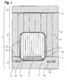
- sleeping berth 1 comprises a bottom shell 2 with upstanding wall approaches 3, on which a wall structure 4 is placed.
- the bottom shell 2 is essentially made of a rectangular base, made of solid material and generally suitable for installation on floor surfaces.
- the upholstery 6 is in turn adapted to the outer shape of the bottom shell 2 and thus forms a kind of tub in the low point of the couch 5 is located.
- a trough-shaped construction of the bottom shell 2 is advantageous because possible, abrupt changes in position of the aircraft, for example, by turbulence, a person lying in the bunk difficult to throw out of this.
- a wall structure 4 closes.
- the wall structure 4 is formed by four air chambers 7, which are enclosed by a film 8 and have in their interior flexible webs 9 for stabilizing their outer shape.
- the flexible webs 9 are at least partially made permeable to air, so that an exchange of air between the individual plots of the air chambers is possible.
- the webs 9 hold the film 8 of the wall structure in a predefined form.
- the mutual distance 10 of the webs 9 is preferably proportional to the thickness of the wall structure 4.
- the distance 10 varies with varying wall thickness.
- the mutual spacing of the webs is smaller than the existing wall thickness at the location of the web.
- the webs 9 of the wall structure 4 are vertically aligned.
- the wall structure 4 is connected to the bottom shell 2, wherein the compound 11 is formed by a zipper.
- the shape of the wall structure 4 is essentially determined by the arrangement and shape of the individual air chambers 7. The smaller the individual air chambers 7, the more complex shaped elements can be produced by assembling these air chambers 7.
- the bottom shell 2 and also the wall structure 4 each have a recess 12, 13 at its edge.
- the two recesses 12, 13 are dimensioned so that they form an access opening 14 for the bunk 1 in the assembled state.
- This access opening 14 is surrounded by a frame 15 which stabilizes the opening 14 and provides attachment surfaces, for example, for a curtain or similar room dividers. In this way, the interior of the bunk 1 can be closed outwardly opaque.
- the wall structure 4 is adjoined by a ceiling 16, likewise consisting of a large number of air chambers, which is connected to the wall structure 4 by means of welded seams 17. Through this fixed connection between the ceiling 16 and wall structure 4, the entire construction of the bunk 1 and in particular the wall structure 4 receives increased strength.
- the ceiling 16 is made of the same film material as the wall structure. 4
- FIG. 1 illustrated embodiment is additionally characterized by the fact that in the bottom shell 2 lamps 18 are mounted, whose light is coupled through the lower end of the wall structure 4 and coupled to the upper end of the wall structure 4 in the ceiling 16. About the film of the wall structure 4 and ceiling 16 16, the light of the bulbs 18 is passed substantially uniformly into the interior of the bunk 1, so that the wall structure 4 and ceiling 16 effectively act even as a lamp.
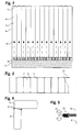
- FIG. 2 shows a bottom shell 2, are received in the light emitting means 18.
- the light 20 of the lamps 18 is coupled into the translucent air chambers 7 and through these passed through. Since the webs 9 extend substantially vertically, the light can propagate from the lower part of the wall structure 4 to its upper part, without suffering appreciable losses.
- the webs 9, which form the air chambers 7, are at least partially permeable to air.
- openings 19 are incorporated in the webs, which allow air exchange between all air chambers 7.
- FIG. 3 shows a plan view of an air chamber 7 with webs contained therein 9.
- the air chamber 7 is enclosed by a film 8.
- tabs 21 are attached to the film 8 on each side of the air chamber 7, which serve the connection between two air chambers.
- zippers, zippers, or hook-and-loop fasteners may be attached to tabs 21 to connect multiple air chambers to a wall structure.
- FIG. 4 shows a cross section of a connection between an air chamber of a wall structure 4 and an air chamber of a ceiling 16. Between the Heilkammem on each side of the air chambers, a tab 21 is attached, which hold the air chambers together.
- the ceiling 16 is applied to the wall structure 4 in such a way that it rests with a lower side on an end face of the wall structure 4. In this way, light from the wall structure 4 can be coupled into the ceiling 16.
- FIG. 5 shows a schematic representation of a zipper 22, which connects the tabs 21 of two adjacent air chambers, such as an air chamber of the wall structure 4 and an air chamber of a ceiling 16 together.
- the tabs can be connected to one another, for example, by means of welded seams or hook-and-loop fasteners.
- wall structure 4 can be connected to the bottom shell 2 with other fasteners, such as a weld or Velcro. Analog applies to the connection between wall structure 4 and ceiling 16, that this can be designed in addition to a realization as a weld seam as a zipper or Velcro.
- the bunk 1 does not have to be designed as a patch on a floor shell 2 wall structure 4 with ceiling 16, but can also be mounted directly on the floor of a passenger compartment or on the seat or deck chair.
- the lighting of the bunk 1 can be done as an alternative to lighting via the light coupled into the wall structure 4 also by conventional, direct lighting, for example by a lamp installed in the bottom shell 2.
- an inflatable structure with air chambers is provided by the invention, which allows a fast and uncomplicated and lightweight construction of a self-supporting space structure, in particular for use in aircraft such as wide-body aircraft.
- the inventive structure allows good sound insulation and an uncomplicated light pipe in its interior.
Landscapes
- Engineering & Computer Science (AREA)
- Aviation & Aerospace Engineering (AREA)
- Building Environments (AREA)
- Tents Or Canopies (AREA)
- Soundproofing, Sound Blocking, And Sound Damping (AREA)
Applications Claiming Priority (2)
| Application Number | Priority Date | Filing Date | Title |
|---|---|---|---|
| CH00631/07A CH710065B1 (de) | 2007-04-17 | 2007-04-17 | Gebilde mit Luftkammern. |
| EP08733781.2A EP2139764B8 (fr) | 2007-04-17 | 2008-04-04 | Structure comprenant une chambre à air |
Related Parent Applications (3)
| Application Number | Title | Priority Date | Filing Date |
|---|---|---|---|
| EP08733781.2A Division EP2139764B8 (fr) | 2007-04-17 | 2008-04-04 | Structure comprenant une chambre à air |
| EP08733781.2A Division-Into EP2139764B8 (fr) | 2007-04-17 | 2008-04-04 | Structure comprenant une chambre à air |
| EP08733781.2 Division | 2008-04-04 |
Publications (3)
| Publication Number | Publication Date |
|---|---|
| EP2554477A2 true EP2554477A2 (fr) | 2013-02-06 |
| EP2554477A3 EP2554477A3 (fr) | 2013-03-13 |
| EP2554477B1 EP2554477B1 (fr) | 2014-04-30 |
Family
ID=38616303
Family Applications (2)
| Application Number | Title | Priority Date | Filing Date |
|---|---|---|---|
| EP12007414.1A Not-in-force EP2554477B1 (fr) | 2007-04-17 | 2008-04-04 | Aéronef avec au moins une structure pour diviser un espace |
| EP08733781.2A Active EP2139764B8 (fr) | 2007-04-17 | 2008-04-04 | Structure comprenant une chambre à air |
Family Applications After (1)
| Application Number | Title | Priority Date | Filing Date |
|---|---|---|---|
| EP08733781.2A Active EP2139764B8 (fr) | 2007-04-17 | 2008-04-04 | Structure comprenant une chambre à air |
Country Status (8)
| Country | Link |
|---|---|
| US (1) | US8528260B2 (fr) |
| EP (2) | EP2554477B1 (fr) |
| CN (1) | CN101743165B (fr) |
| BR (1) | BRPI0810438B1 (fr) |
| CA (1) | CA2690071C (fr) |
| CH (1) | CH710065B1 (fr) |
| ES (1) | ES2477265T3 (fr) |
| WO (1) | WO2008124956A1 (fr) |
Cited By (1)
| Publication number | Priority date | Publication date | Assignee | Title |
|---|---|---|---|---|
| US12240608B2 (en) | 2021-07-02 | 2025-03-04 | Airbus Operations Gmbh | Inflatable separating region for a vehicle interior |
Families Citing this family (10)
| Publication number | Priority date | Publication date | Assignee | Title |
|---|---|---|---|---|
| CH710065B1 (de) * | 2007-04-17 | 2016-02-29 | Lantal Textiles Ag | Gebilde mit Luftkammern. |
| CN101949196B (zh) * | 2010-09-17 | 2012-05-30 | 天津科技大学 | 充气式的墙体材料以及采用该墙体材料的充气式微型冷库 |
| CN102407935A (zh) * | 2010-09-20 | 2012-04-11 | 中橡集团沈阳橡胶研究设计院 | 应急托举气囊 |
| US20140175219A1 (en) * | 2012-12-11 | 2014-06-26 | C&D Zodiac, Inc. | Fixed aircraft aisle partition with lighting |
| CN103192980A (zh) * | 2013-04-09 | 2013-07-10 | 中国人民解放军国防科学技术大学 | 基于经纬网络的充气机翼及其制造方法 |
| US20150042822A1 (en) * | 2013-08-12 | 2015-02-12 | Tu Le | Inflatable photo booth |
| CN109072761B (zh) * | 2016-02-10 | 2023-09-05 | 詹姆斯·吉·派乐 | 增强型可充胀声音衰减系统 |
| US20190143856A1 (en) * | 2017-11-13 | 2019-05-16 | Gulfstream Aerospace Corporation | Seat assembly that includes a modular foam arrangement and a pneumatic bladder sub-assembly and method for fabricating the same |
| US11497322B2 (en) | 2019-11-15 | 2022-11-15 | Sleep Number Corporation | Zipper mattress attachment |
| EP3919383A1 (fr) * | 2020-06-04 | 2021-12-08 | Koninklijke Fabriek Inventum B.V. | Parois d'isolation gonflables pour cabines d'aéronef |
Family Cites Families (22)
| Publication number | Priority date | Publication date | Assignee | Title |
|---|---|---|---|---|
| US2960292A (en) * | 1959-03-16 | 1960-11-15 | Pitta Manuel | Safety enclosure for aircraft passengers |
| DE1918240A1 (de) * | 1969-04-10 | 1970-10-15 | Norbert Koenemann | Aufblasbare Gebaeude |
| US3629875A (en) * | 1970-02-04 | 1971-12-28 | Doris I Dow | Portable inflatable enclosure for personal use |
| FR2188007A1 (fr) * | 1972-06-06 | 1974-01-18 | Romalo Johann | |
| GB1465698A (en) * | 1973-07-02 | 1977-02-23 | Westland Aircraft Ltd | Seats |
| US4040210A (en) * | 1976-06-01 | 1977-08-09 | Land Edgel T | Low cost storm window |
| US4255907A (en) * | 1978-11-03 | 1981-03-17 | Lightell Wilbur G | Inflatable storm window |
| DE3802331A1 (de) * | 1988-01-27 | 1989-09-07 | Messerschmitt Boelkow Blohm | Sicherheitseinrichtung fuer flugzeuge |
| GB8916988D0 (en) * | 1989-07-25 | 1989-09-13 | Goddard David L | Inflatable housing |
| US5097548A (en) * | 1990-04-18 | 1992-03-24 | Heck Douglas M | Inflatable self-supporting cover |
| US5429851A (en) * | 1993-05-05 | 1995-07-04 | Tracor, Inc. | Expandable rigid structure |
| US5813172A (en) * | 1997-04-04 | 1998-09-29 | Mcnally; Mark F. | Structural inflatable wall panels |
| CN2313469Y (zh) * | 1997-12-02 | 1999-04-14 | 刘灿希 | 可调式充气床垫 |
| CN2341484Y (zh) * | 1998-08-21 | 1999-10-06 | 李景唐 | 一种结构多室腔气垫的长方体形气室 |
| US6467221B1 (en) * | 2000-08-23 | 2002-10-22 | Bigelow Development Aerospace | Spacecraft sleeping berth |
| CN2595262Y (zh) * | 2001-07-14 | 2003-12-31 | 陈刚 | 一种气垫 |
| US7293740B2 (en) * | 2004-07-27 | 2007-11-13 | The Boeing Company | Aircraft crewmember articulating berth system |
| CN2822385Y (zh) * | 2005-04-04 | 2006-10-04 | 柏威美国有限公司 | 一种稳定支撑结构的充气床 |
| US7992678B2 (en) * | 2005-05-12 | 2011-08-09 | Pilaar James G | Inflatable sound attenuation system |
| FR2904965B1 (fr) * | 2006-08-18 | 2008-11-14 | Airbus Sas | Aeronef a espace utile optimise et procede pour optimiser l'espace utile d'un aeronef |
| US7513457B2 (en) * | 2006-09-20 | 2009-04-07 | The Boeing Company | Compartment for a transportation device and its installation |
| CH710065B1 (de) * | 2007-04-17 | 2016-02-29 | Lantal Textiles Ag | Gebilde mit Luftkammern. |
-
2007
- 2007-04-17 CH CH00631/07A patent/CH710065B1/de unknown
-
2008
- 2008-04-04 EP EP12007414.1A patent/EP2554477B1/fr not_active Not-in-force
- 2008-04-04 CN CN200880020663.2A patent/CN101743165B/zh active Active
- 2008-04-04 EP EP08733781.2A patent/EP2139764B8/fr active Active
- 2008-04-04 WO PCT/CH2008/000153 patent/WO2008124956A1/fr not_active Ceased
- 2008-04-04 US US12/596,304 patent/US8528260B2/en active Active
- 2008-04-04 CA CA2690071A patent/CA2690071C/fr active Active
- 2008-04-04 ES ES12007414.1T patent/ES2477265T3/es active Active
- 2008-04-04 BR BRPI0810438A patent/BRPI0810438B1/pt active IP Right Grant
Non-Patent Citations (1)
| Title |
|---|
| None |
Cited By (1)
| Publication number | Priority date | Publication date | Assignee | Title |
|---|---|---|---|---|
| US12240608B2 (en) | 2021-07-02 | 2025-03-04 | Airbus Operations Gmbh | Inflatable separating region for a vehicle interior |
Also Published As
| Publication number | Publication date |
|---|---|
| US8528260B2 (en) | 2013-09-10 |
| ES2477265T3 (es) | 2014-07-16 |
| CH710065B1 (de) | 2016-02-29 |
| EP2554477A3 (fr) | 2013-03-13 |
| CN101743165A (zh) | 2010-06-16 |
| EP2554477B1 (fr) | 2014-04-30 |
| EP2139764A1 (fr) | 2010-01-06 |
| CA2690071A1 (fr) | 2008-10-23 |
| CN101743165B (zh) | 2016-08-10 |
| EP2139764B8 (fr) | 2015-06-03 |
| WO2008124956A1 (fr) | 2008-10-23 |
| BRPI0810438B1 (pt) | 2019-12-24 |
| BRPI0810438A2 (pt) | 2014-10-14 |
| US20100140401A1 (en) | 2010-06-10 |
| EP2139764B1 (fr) | 2015-04-29 |
| CA2690071C (fr) | 2014-05-27 |
Similar Documents
| Publication | Publication Date | Title |
|---|---|---|
| EP2554477B1 (fr) | Aéronef avec au moins une structure pour diviser un espace | |
| DE2630210C3 (de) | Vorrichtung zur liegenden Beförderung von Personen insbesondere in Luftfahrzeugen | |
| DE3802331C2 (fr) | ||
| DE69827725T2 (de) | Rettungsvorrichtung für Ruhezone im oberen Bereich der Flugzeugkabine | |
| DE602005006280T2 (de) | Modulares wandkonstruktionssystem für flugzeugkabinen | |
| DE102014205106A1 (de) | Schlafbox, Schlafboxenanordnung und Flugzeugbereich | |
| EP2921615B1 (fr) | Tente gonflable, notamment tente étoile | |
| EP0035955A2 (fr) | Avion avec récipient de transport ou conteneur | |
| DE102009004987A1 (de) | Verschiebbarer Sitz für schnelle Layoutanpassungen | |
| EP3452331A1 (fr) | Pick-up | |
| DE3817590A1 (de) | Anordnung einer kabineneinheit und verfahren zur schaffung derselben | |
| EP2477891B1 (fr) | Dispositif d'habillage d'une cabine d'un avion et procédé d'habillage d'une cabine d'un avion | |
| DE102008024509A1 (de) | Integrierte akustische Entkopplung in einem Aufenthaltsmodul | |
| DE102017106411B4 (de) | Multifunktionales Containersystem zum Herstellen eines in einem Frachtladeraum eines Flugzeugs verwendbaren Containers | |
| DE3529556A1 (de) | Mobiles containersystem | |
| EP3807139B1 (fr) | Véhicule ferroviaire comprenant une caisse de véhicule et une structure de plafond disposée à l'intérieur de la caisse de véhicule | |
| EP3002173B1 (fr) | Vehicule sur rail dote d'un conduit de climatiseur de toit | |
| DE102007009499A1 (de) | Faltbare Raumauskleidung für ein Flugzeug und Flugzeug mit einer solchen | |
| DE102005035752B4 (de) | Passagierabteil | |
| DE3922579A1 (de) | Sicherheitseinrichtung, insbesondere fuer flugzeuge | |
| DE29809772U1 (de) | Begehbare raumförmige Container-Einheit | |
| DE60226213T2 (de) | Selbsttragende krankentrage für flugzeuge | |
| EP2953854A1 (fr) | Dispositif de conditionnement d'un volume spatial structuralement non fermé, au moyen d'un flux massique de gaz | |
| DE102006017596B4 (de) | Kabinenabteil und dessen Verwendung in einem Luftfahrzeug | |
| WO2013143684A2 (fr) | Cuisine modulaire pour avion |
Legal Events
| Date | Code | Title | Description |
|---|---|---|---|
| PUAI | Public reference made under article 153(3) epc to a published international application that has entered the european phase |
Free format text: ORIGINAL CODE: 0009012 |
|
| AC | Divisional application: reference to earlier application |
Ref document number: 2139764 Country of ref document: EP Kind code of ref document: P |
|
| AK | Designated contracting states |
Kind code of ref document: A2 Designated state(s): AT BE BG CH CY CZ DE DK EE ES FI FR GB GR HR HU IE IS IT LI LT LU LV MC MT NL NO PL PT RO SE SI SK TR |
|
| PUAL | Search report despatched |
Free format text: ORIGINAL CODE: 0009013 |
|
| RIN1 | Information on inventor provided before grant (corrected) |
Inventor name: SUTER, IRIS Inventor name: VON BALLMOOS, ROLAND Inventor name: RADANOVIC, DRAGAN Inventor name: GUEHMANN, ANDREAS Inventor name: KEREKES, LASZLO |
|
| AK | Designated contracting states |
Kind code of ref document: A3 Designated state(s): AT BE BG CH CY CZ DE DK EE ES FI FR GB GR HR HU IE IS IT LI LT LU LV MC MT NL NO PL PT RO SE SI SK TR |
|
| RIC1 | Information provided on ipc code assigned before grant |
Ipc: B64D 11/00 20060101AFI20130204BHEP |
|
| 17P | Request for examination filed |
Effective date: 20130812 |
|
| RBV | Designated contracting states (corrected) |
Designated state(s): AT BE BG CH CY CZ DE DK EE ES FI FR GB GR HR HU IE IS IT LI LT LU LV MC MT NL NO PL PT RO SE SI SK TR |
|
| GRAP | Despatch of communication of intention to grant a patent |
Free format text: ORIGINAL CODE: EPIDOSNIGR1 |
|
| INTG | Intention to grant announced |
Effective date: 20131108 |
|
| GRAS | Grant fee paid |
Free format text: ORIGINAL CODE: EPIDOSNIGR3 |
|
| GRAA | (expected) grant |
Free format text: ORIGINAL CODE: 0009210 |
|
| RAP1 | Party data changed (applicant data changed or rights of an application transferred) |
Owner name: LANTAL TEXTILES AG |
|
| AC | Divisional application: reference to earlier application |
Ref document number: 2139764 Country of ref document: EP Kind code of ref document: P |
|
| AK | Designated contracting states |
Kind code of ref document: B1 Designated state(s): AT BE BG CH CY CZ DE DK EE ES FI FR GB GR HR HU IE IS IT LI LT LU LV MC MT NL NO PL PT RO SE SI SK TR |
|
| REG | Reference to a national code |
Ref country code: GB Ref legal event code: FG4D Free format text: NOT ENGLISH Ref country code: CH Ref legal event code: EP |
|
| REG | Reference to a national code |
Ref country code: AT Ref legal event code: REF Ref document number: 664934 Country of ref document: AT Kind code of ref document: T Effective date: 20140515 |
|
| REG | Reference to a national code |
Ref country code: IE Ref legal event code: FG4D Free format text: LANGUAGE OF EP DOCUMENT: GERMAN |
|
| REG | Reference to a national code |
Ref country code: DE Ref legal event code: R096 Ref document number: 502008011697 Country of ref document: DE Effective date: 20140612 |
|
| REG | Reference to a national code |
Ref country code: ES Ref legal event code: FG2A Ref document number: 2477265 Country of ref document: ES Kind code of ref document: T3 Effective date: 20140716 |
|
| REG | Reference to a national code |
Ref country code: NL Ref legal event code: T3 |
|
| REG | Reference to a national code |
Ref country code: LT Ref legal event code: MG4D |
|
| REG | Reference to a national code |
Ref country code: CH Ref legal event code: NV Representative=s name: KELLER AND PARTNER PATENTANWAELTE AG, CH |
|
| PG25 | Lapsed in a contracting state [announced via postgrant information from national office to epo] |
Ref country code: BG Free format text: LAPSE BECAUSE OF FAILURE TO SUBMIT A TRANSLATION OF THE DESCRIPTION OR TO PAY THE FEE WITHIN THE PRESCRIBED TIME-LIMIT Effective date: 20140730 Ref country code: NO Free format text: LAPSE BECAUSE OF FAILURE TO SUBMIT A TRANSLATION OF THE DESCRIPTION OR TO PAY THE FEE WITHIN THE PRESCRIBED TIME-LIMIT Effective date: 20140730 Ref country code: GR Free format text: LAPSE BECAUSE OF FAILURE TO SUBMIT A TRANSLATION OF THE DESCRIPTION OR TO PAY THE FEE WITHIN THE PRESCRIBED TIME-LIMIT Effective date: 20140731 Ref country code: CY Free format text: LAPSE BECAUSE OF FAILURE TO SUBMIT A TRANSLATION OF THE DESCRIPTION OR TO PAY THE FEE WITHIN THE PRESCRIBED TIME-LIMIT Effective date: 20140430 Ref country code: IS Free format text: LAPSE BECAUSE OF FAILURE TO SUBMIT A TRANSLATION OF THE DESCRIPTION OR TO PAY THE FEE WITHIN THE PRESCRIBED TIME-LIMIT Effective date: 20140830 Ref country code: LT Free format text: LAPSE BECAUSE OF FAILURE TO SUBMIT A TRANSLATION OF THE DESCRIPTION OR TO PAY THE FEE WITHIN THE PRESCRIBED TIME-LIMIT Effective date: 20140430 Ref country code: FI Free format text: LAPSE BECAUSE OF FAILURE TO SUBMIT A TRANSLATION OF THE DESCRIPTION OR TO PAY THE FEE WITHIN THE PRESCRIBED TIME-LIMIT Effective date: 20140430 |
|
| PG25 | Lapsed in a contracting state [announced via postgrant information from national office to epo] |
Ref country code: PL Free format text: LAPSE BECAUSE OF FAILURE TO SUBMIT A TRANSLATION OF THE DESCRIPTION OR TO PAY THE FEE WITHIN THE PRESCRIBED TIME-LIMIT Effective date: 20140430 Ref country code: LV Free format text: LAPSE BECAUSE OF FAILURE TO SUBMIT A TRANSLATION OF THE DESCRIPTION OR TO PAY THE FEE WITHIN THE PRESCRIBED TIME-LIMIT Effective date: 20140430 Ref country code: HR Free format text: LAPSE BECAUSE OF FAILURE TO SUBMIT A TRANSLATION OF THE DESCRIPTION OR TO PAY THE FEE WITHIN THE PRESCRIBED TIME-LIMIT Effective date: 20140430 Ref country code: SE Free format text: LAPSE BECAUSE OF FAILURE TO SUBMIT A TRANSLATION OF THE DESCRIPTION OR TO PAY THE FEE WITHIN THE PRESCRIBED TIME-LIMIT Effective date: 20140430 |
|
| PG25 | Lapsed in a contracting state [announced via postgrant information from national office to epo] |
Ref country code: PT Free format text: LAPSE BECAUSE OF FAILURE TO SUBMIT A TRANSLATION OF THE DESCRIPTION OR TO PAY THE FEE WITHIN THE PRESCRIBED TIME-LIMIT Effective date: 20140901 |
|
| PG25 | Lapsed in a contracting state [announced via postgrant information from national office to epo] |
Ref country code: RO Free format text: LAPSE BECAUSE OF FAILURE TO SUBMIT A TRANSLATION OF THE DESCRIPTION OR TO PAY THE FEE WITHIN THE PRESCRIBED TIME-LIMIT Effective date: 20140430 Ref country code: EE Free format text: LAPSE BECAUSE OF FAILURE TO SUBMIT A TRANSLATION OF THE DESCRIPTION OR TO PAY THE FEE WITHIN THE PRESCRIBED TIME-LIMIT Effective date: 20140430 Ref country code: SK Free format text: LAPSE BECAUSE OF FAILURE TO SUBMIT A TRANSLATION OF THE DESCRIPTION OR TO PAY THE FEE WITHIN THE PRESCRIBED TIME-LIMIT Effective date: 20140430 Ref country code: DK Free format text: LAPSE BECAUSE OF FAILURE TO SUBMIT A TRANSLATION OF THE DESCRIPTION OR TO PAY THE FEE WITHIN THE PRESCRIBED TIME-LIMIT Effective date: 20140430 |
|
| REG | Reference to a national code |
Ref country code: DE Ref legal event code: R097 Ref document number: 502008011697 Country of ref document: DE |
|
| PLBE | No opposition filed within time limit |
Free format text: ORIGINAL CODE: 0009261 |
|
| STAA | Information on the status of an ep patent application or granted ep patent |
Free format text: STATUS: NO OPPOSITION FILED WITHIN TIME LIMIT |
|
| REG | Reference to a national code |
Ref country code: FR Ref legal event code: PLFP Year of fee payment: 8 |
|
| PG25 | Lapsed in a contracting state [announced via postgrant information from national office to epo] |
Ref country code: IT Free format text: LAPSE BECAUSE OF FAILURE TO SUBMIT A TRANSLATION OF THE DESCRIPTION OR TO PAY THE FEE WITHIN THE PRESCRIBED TIME-LIMIT Effective date: 20140430 |
|
| REG | Reference to a national code |
Ref country code: CH Ref legal event code: PCAR Free format text: NEW ADDRESS: EIGERSTRASSE 2 POSTFACH, 3000 BERN 14 (CH) |
|
| 26N | No opposition filed |
Effective date: 20150202 |
|
| REG | Reference to a national code |
Ref country code: DE Ref legal event code: R097 Ref document number: 502008011697 Country of ref document: DE Effective date: 20150202 |
|
| PG25 | Lapsed in a contracting state [announced via postgrant information from national office to epo] |
Ref country code: SI Free format text: LAPSE BECAUSE OF FAILURE TO SUBMIT A TRANSLATION OF THE DESCRIPTION OR TO PAY THE FEE WITHIN THE PRESCRIBED TIME-LIMIT Effective date: 20140430 |
|
| PG25 | Lapsed in a contracting state [announced via postgrant information from national office to epo] |
Ref country code: CZ Free format text: LAPSE BECAUSE OF NON-PAYMENT OF DUE FEES Effective date: 20150404 |
|
| PG25 | Lapsed in a contracting state [announced via postgrant information from national office to epo] |
Ref country code: LU Free format text: LAPSE BECAUSE OF FAILURE TO SUBMIT A TRANSLATION OF THE DESCRIPTION OR TO PAY THE FEE WITHIN THE PRESCRIBED TIME-LIMIT Effective date: 20150404 Ref country code: MC Free format text: LAPSE BECAUSE OF FAILURE TO SUBMIT A TRANSLATION OF THE DESCRIPTION OR TO PAY THE FEE WITHIN THE PRESCRIBED TIME-LIMIT Effective date: 20140430 |
|
| REG | Reference to a national code |
Ref country code: NL Ref legal event code: MM Effective date: 20150501 |
|
| REG | Reference to a national code |
Ref country code: IE Ref legal event code: MM4A |
|
| PG25 | Lapsed in a contracting state [announced via postgrant information from national office to epo] |
Ref country code: NL Free format text: LAPSE BECAUSE OF NON-PAYMENT OF DUE FEES Effective date: 20150501 |
|
| REG | Reference to a national code |
Ref country code: FR Ref legal event code: PLFP Year of fee payment: 9 |
|
| PG25 | Lapsed in a contracting state [announced via postgrant information from national office to epo] |
Ref country code: IE Free format text: LAPSE BECAUSE OF NON-PAYMENT OF DUE FEES Effective date: 20150404 |
|
| REG | Reference to a national code |
Ref country code: AT Ref legal event code: MM01 Ref document number: 664934 Country of ref document: AT Kind code of ref document: T Effective date: 20150404 |
|
| PG25 | Lapsed in a contracting state [announced via postgrant information from national office to epo] |
Ref country code: AT Free format text: LAPSE BECAUSE OF NON-PAYMENT OF DUE FEES Effective date: 20150404 |
|
| PG25 | Lapsed in a contracting state [announced via postgrant information from national office to epo] |
Ref country code: MT Free format text: LAPSE BECAUSE OF FAILURE TO SUBMIT A TRANSLATION OF THE DESCRIPTION OR TO PAY THE FEE WITHIN THE PRESCRIBED TIME-LIMIT Effective date: 20140430 |
|
| REG | Reference to a national code |
Ref country code: FR Ref legal event code: PLFP Year of fee payment: 10 |
|
| PG25 | Lapsed in a contracting state [announced via postgrant information from national office to epo] |
Ref country code: HU Free format text: LAPSE BECAUSE OF FAILURE TO SUBMIT A TRANSLATION OF THE DESCRIPTION OR TO PAY THE FEE WITHIN THE PRESCRIBED TIME-LIMIT; INVALID AB INITIO Effective date: 20080404 |
|
| PG25 | Lapsed in a contracting state [announced via postgrant information from national office to epo] |
Ref country code: ES Free format text: LAPSE BECAUSE OF NON-PAYMENT OF DUE FEES Effective date: 20150405 |
|
| PG25 | Lapsed in a contracting state [announced via postgrant information from national office to epo] |
Ref country code: BE Free format text: LAPSE BECAUSE OF NON-PAYMENT OF DUE FEES Effective date: 20150430 |
|
| PG25 | Lapsed in a contracting state [announced via postgrant information from national office to epo] |
Ref country code: TR Free format text: LAPSE BECAUSE OF FAILURE TO SUBMIT A TRANSLATION OF THE DESCRIPTION OR TO PAY THE FEE WITHIN THE PRESCRIBED TIME-LIMIT Effective date: 20140430 |
|
| REG | Reference to a national code |
Ref country code: FR Ref legal event code: PLFP Year of fee payment: 11 |
|
| REG | Reference to a national code |
Ref country code: ES Ref legal event code: FD2A Effective date: 20180704 |
|
| PGFP | Annual fee paid to national office [announced via postgrant information from national office to epo] |
Ref country code: CH Payment date: 20200319 Year of fee payment: 13 |
|
| PGFP | Annual fee paid to national office [announced via postgrant information from national office to epo] |
Ref country code: FR Payment date: 20200330 Year of fee payment: 13 |
|
| PGFP | Annual fee paid to national office [announced via postgrant information from national office to epo] |
Ref country code: DE Payment date: 20200420 Year of fee payment: 13 |
|
| PGFP | Annual fee paid to national office [announced via postgrant information from national office to epo] |
Ref country code: GB Payment date: 20200430 Year of fee payment: 13 |
|
| REG | Reference to a national code |
Ref country code: CH Ref legal event code: PFA Owner name: LANTAL TEXTILES AG, CH Free format text: FORMER OWNER: LANTAL TEXTILES AG, CH |
|
| REG | Reference to a national code |
Ref country code: DE Ref legal event code: R119 Ref document number: 502008011697 Country of ref document: DE |
|
| GBPC | Gb: european patent ceased through non-payment of renewal fee |
Effective date: 20210404 |
|
| PG25 | Lapsed in a contracting state [announced via postgrant information from national office to epo] |
Ref country code: LI Free format text: LAPSE BECAUSE OF NON-PAYMENT OF DUE FEES Effective date: 20210430 Ref country code: CH Free format text: LAPSE BECAUSE OF NON-PAYMENT OF DUE FEES Effective date: 20210430 Ref country code: FR Free format text: LAPSE BECAUSE OF NON-PAYMENT OF DUE FEES Effective date: 20210430 Ref country code: GB Free format text: LAPSE BECAUSE OF NON-PAYMENT OF DUE FEES Effective date: 20210404 Ref country code: DE Free format text: LAPSE BECAUSE OF NON-PAYMENT OF DUE FEES Effective date: 20211103 |