EP2554529B1 - Détonateur de sécurité - Google Patents
Détonateur de sécurité Download PDFInfo
- Publication number
- EP2554529B1 EP2554529B1 EP12174520.2A EP12174520A EP2554529B1 EP 2554529 B1 EP2554529 B1 EP 2554529B1 EP 12174520 A EP12174520 A EP 12174520A EP 2554529 B1 EP2554529 B1 EP 2554529B1
- Authority
- EP
- European Patent Office
- Prior art keywords
- detonator
- stage
- plate
- projected
- insulation means
- Prior art date
- Legal status (The legal status is an assumption and is not a legal conclusion. Google has not performed a legal analysis and makes no representation as to the accuracy of the status listed.)
- Active
Links
Images

Classifications
-
- F—MECHANICAL ENGINEERING; LIGHTING; HEATING; WEAPONS; BLASTING
- F42—AMMUNITION; BLASTING
- F42D—BLASTING
- F42D5/00—Safety arrangements
-
- C—CHEMISTRY; METALLURGY
- C06—EXPLOSIVES; MATCHES
- C06C—DETONATING OR PRIMING DEVICES; FUSES; CHEMICAL LIGHTERS; PYROPHORIC COMPOSITIONS
- C06C7/00—Non-electric detonators; Blasting caps; Primers
-
- F—MECHANICAL ENGINEERING; LIGHTING; HEATING; WEAPONS; BLASTING
- F42—AMMUNITION; BLASTING
- F42B—EXPLOSIVE CHARGES, e.g. FOR BLASTING, FIREWORKS, AMMUNITION
- F42B3/00—Blasting cartridges, i.e. case and explosive
- F42B3/10—Initiators therefor
-
- F—MECHANICAL ENGINEERING; LIGHTING; HEATING; WEAPONS; BLASTING
- F42—AMMUNITION; BLASTING
- F42B—EXPLOSIVE CHARGES, e.g. FOR BLASTING, FIREWORKS, AMMUNITION
- F42B3/00—Blasting cartridges, i.e. case and explosive
- F42B3/10—Initiators therefor
- F42B3/113—Initiators therefor activated by optical means, e.g. laser, flashlight
-
- F—MECHANICAL ENGINEERING; LIGHTING; HEATING; WEAPONS; BLASTING
- F42—AMMUNITION; BLASTING
- F42B—EXPLOSIVE CHARGES, e.g. FOR BLASTING, FIREWORKS, AMMUNITION
- F42B3/00—Blasting cartridges, i.e. case and explosive
- F42B3/10—Initiators therefor
- F42B3/18—Safety initiators resistant to premature firing by static electricity or stray currents
Definitions
- the technical field of the invention is that of detonators plate or projected element.
- This type of detonator as described in the patent US6374740 comprises a body in which there is a first stage, or inflammatory stage, comprising at least a first pyrotechnic composition or an explosive secondary explosive.
- a relay stage comprising at least one secondary explosive.
- the first composition may be initiated by an optical means such as an optical fiber or an electrical means (hot wire) while the secondary explosive is initiatable by an impact.
- a thin plate metal or plastic
- the plate is projected onto the secondary explosive which will then be initiated following the energy of the shock provided by the plate.
- This operation has a disadvantage from the point of view of safety.
- the first composition may react and cause the projection of the plate and thereby the reaction of the secondary explosive and the whole of the pyrotechnic chain.
- the invention proposes to reduce the sensitivity to the temperature rise of the igniter stage.
- the subject of the invention is a detonator comprising a plate projected by an igniting stage comprising at least less a first pyrotechnic composition and / or a first explosive, plate projected on a relay stage comprising at least one secondary explosive, detonator characterized in that it comprises a thermal insulation means surrounding the igniter stage to delay its temperature rise .
- the thermal insulation means comprises a casing made of a ceramic material.
- the thermal insulation means comprises an envelope made of a plastic or composite material.
- the thermal insulation means associates an envelope made of a first thermal insulating material and closed by a plug made of a second thermal insulating material.
- the material or materials constituting the thermal insulation means have a thermal conductivity of less than 0.24 W.m -1 .K -1 .
- the thickness of the insulating means will preferably be greater than 0.5 mm.
- the first pyrotechnic composition or the first explosive of the igniter stage is in contact with the end of an optical fiber.
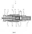
- a detonator 1 comprises a substantially cylindrical body 2 having three parts 2a, 2b and 2c.
- the central portion 2b of the body has an external thread 2d for securing the detonator with a mounting for receiving such a munition (assembly not shown).
- a sheathed optical fiber 3 passes through the rear part 2a of the body.
- the optical fiber 3 opens into an ignition stage 10 in contact with a first photosensitive pyrotechnic composition 4.
- a first photosensitive pyrotechnic composition 4 is described by the patent FR2914056 .
- a composition combining zirconium and potassium perchlorate is conventional and it is not necessary to describe it in more detail.
- Other types of pyrotechnic compositions may be used such as: boron / potassium nitrate, boron / zirconium / potassium nitrate, etc.
- the secondary explosive may be pure or incorporate an optical dopant as described by the patent EP1742009 .
- a layer of pyrotechnic ignition composition (such as a zirconium / potassium perchlorate composition) in contact with the optical fiber 3 and associated with the optical fiber 3 will be associated with the level of the igniter stage 10.
- a layer of a secondary explosive explosion for example octogen.
- the patent EP1306643 describes such an association of an ignition composition and a secondary explosive.
- the igniter stage 10 comprises a first composition (and / or a secondary explosion explosive) having a particle size perfectly controlled and relatively reduced (less than or equal to 60 micrometers).
- This first pyrotechnic composition is loaded into a case 5 which is enveloped by a thermal insulation means 12.
- This thermal insulation means 12 comprises a casing made of a ceramic material, a plastic or composite material.
- the plastic used may for example be a thermoplastic type polyamide PA66.
- a ceramic material may for example be based on silica and selected from ceramics having a high thermal resistance. Ceramic is preferred because, due to its porosity, its natural thermal insulation qualities are important.
- the igniter stage thus constituted comprises a projectable metal plate 6 (also referred to herein as the projected element 6) placed on the ceramic coating on the outside thereof, opposite to the optical fiber 3.
- the screwing of the rear portion 2a on the central portion 2b allows to apply the bottom of the igniter stage 10 (covered by the insulating means 12) against the plate 6 which is then pinched between the insulator 12 and the front portion 2c of the body.
- the igniter stage is thus maintained in position thanks to a threading 9 solidarisant the rear part of the body 2a at the central part of the body 2b.
- the metal plate 6 is supported by its periphery on a shoulder of the front portion 2c of the body 2.
- a secondary explosive 7 sensitive to shock which forms a relay stage.
- the distance D will be chosen by those skilled in the art as being that which makes it possible to obtain the optimal projection speed at the shock release of the secondary explosive 7 by virtue of the characteristics of the igniter stage 10, and therefore especially of the nature and the mass of the first composition 4 and the mass of the plate 6 and that of the insulating means 12.
- the invention proposes that the igniter stage 10 is sufficiently thermally insulated by the thermal insulation means 12 so that it is protected from heat or it does not burns or blows only after the secondary explosive 7 of the front part 2c of the detonator 2 has itself been burned or deflagrated.
- the skilled person will determine the minimum thickness E (thickness ranging from 0.5 to 2 mm, thickness better visible at the figure 2 ) of the insulating means 12 to ensure a sufficient time lag between the arrival at a given temperature level outside and the arrival at the same level inside the insulating means 12.
- the thickness will be chosen such that there is a time lag of at least 30 seconds between the instant when the temperature outside the insulation means 12 is 230 ° C. and the instant when the temperature at the inside of the insulating means 12 is 230 ° C.
- the primary pyrotechnic composition 4 being during this interval protected by the thermal insulation means, it does not react. Beyond 30 seconds, she can then react without fear of triggering a detonation.
- the thermal insulation means may associate an envelope 12a made of a first thermal insulating material and closed by a plug 12b made of a second thermal insulating material.
- the envelope 12a receiving the pyrotechnic composition may for example be made of ceramic material and the plug 12b may be made of plastic.
- the ceramic is very fragile, the use of a plastic plug allows to seal all without risk of cracking.
- the loaded case 5, or directly loading secondary explosive 4 in the case where no case is used can be covered ceramic by sintering for example.
- the invention has been described with an igniter stage initiated by an optical fiber, but the invention can also be implemented with an igniter stage initiated in a more conventional manner by electrical energy, for example a hot-wire igniter. or exploded wire.
Landscapes
- Engineering & Computer Science (AREA)
- General Engineering & Computer Science (AREA)
- Physics & Mathematics (AREA)
- Optics & Photonics (AREA)
- Chemical & Material Sciences (AREA)
- Organic Chemistry (AREA)
- Air Bags (AREA)
Description
- Le domaine technique de l'invention est celui des détonateurs à plaque ou élément projeté.
- Ce type de détonateur tel que décrit dans le brevet
US6374740 comporte un corps dans lequel se trouve un premier étage, ou étage inflammateur, comprenant au moins une première composition pyrotechnique ou un explosif secondaire déflagrant. En regard de ce premier étage inflammateur se trouve un étage relais comprenant au moins un explosif secondaire. La première composition peut être initiée par un moyen optique tel qu'une fibre optique ou un moyen électrique (fil chaud) alors que l'explosif secondaire est initiable par un choc. C'est pourquoi une plaque mince (de métal ou de plastique) est placée entre les deux étages pyrotechniques. Suite à l'initiation sur commande de la première composition, la plaque est projetée sur l'explosif secondaire qui va alors s'initier suite à l'énergie du choc fourni par la plaque. - Ce fonctionnement présente un inconvénient du point de vue de la sécurité.
- En cas d'exposition du détonateur à une forte chaleur due à un incendie par exemple, la première composition risque de réagir et de provoquer la projection de la plaque et par-là même la réaction de l'explosif secondaire et de l'ensemble de la chaine pyrotechnique.
- Pour remédier à ce problème, l'invention se propose de diminuer la sensibilité à l'élévation de température de l'étage inflammateur.
- Ainsi l'invention a pour objet un détonateur comportant une plaque projetée par un étage inflammateur comprenant au moins une première composition pyrotechnique et/ou un premier explosif, plaque projetée sur un étage relais comprenant au moins un explosif secondaire, détonateur caractérisé en ce qu'il comporte un moyen d'isolation thermique entourant l'étage inflammateur pour retarder son élévation de température.
- Selon une caractéristique de l'invention, le moyen d'isolation thermique comporte une enveloppe réalisée en un matériau céramique.
- Selon une autre caractéristique de l'invention, le moyen d'isolation thermique comporte une enveloppe réalisée en une matière plastique ou composite.
- Avantageusement, le moyen d'isolation thermique associe une enveloppe réalisée en un premier matériau isolant thermique et obturée par un bouchon réalisé en un deuxième matériau isolant thermique.
- Selon une caractéristique de l'invention, le ou les matériaux constituant le moyen d'isolation thermique présentent une conductivité thermique inférieure à 0,24W.m-1.K-1.
- Dans ce cas, l'épaisseur du moyen d'isolation sera de préférence supérieure à 0,5 mm.
- Avantageusement, la première composition pyrotechnique ou le premier explosif de l'étage inflammateur est en contact avec l'extrémité d'une fibre optique.
- L'invention sera mieux comprise à la lecture de la description suivante, description illustrée par les dessins annexés dans lesquels :
- La
figure 1 représente un détonateur en coupe longitudinale selon un premier mode de réalisation de l'invention, - La
figure 2 représente un détonateur en coupe longitudinale selon un second mode de réalisation de l'invention. - Selon la
figure 1 , un détonateur 1 comporte un corps 2 sensiblement cylindrique comportant trois parties 2a, 2b et 2c. La partie centrale 2b du corps comporte un filetage externe 2d permettant de solidariser le détonateur avec un montage destiné à le recevoir tel qu'une munition (montage non représenté). - Coaxialement au corps 2 une fibre optique 3 gainée traverse la partie arrière 2a du corps. La fibre optique 3 débouche dans un étage inflammateur 10 au contact d'une première composition pyrotechnique 4 photosensible. Un tel montage de fibre optique en contact avec une composition pyrotechnique est décrit par le brevet
FR2914056 - Comme le précise ce brevet
FR2914056 - On pourra aussi remplacer la première composition pyrotechnique 4 par un explosif secondaire pouvant adopter un régime déflagrant. L'explosif secondaire pourra être pur ou incorporer un dopant optique tel que décrit par le brevet
EP1742009 . - D'une façon préférée on associera au niveau de l'étage inflammateur 10 une couche de composition pyrotechnique d'allumage (telle qu'une composition zirconium/Perchlorate de potassium) en contact avec la fibre optique 3 et qui allumera une couche d'un explosif secondaire déflagrant, par exemple de l'octogène. Le brevet
EP1306643 décrit une telle association d'une composition d'allumage et d'un explosif secondaire. - L'essentiel pour que l'allumage optique soit assuré est que l'étage inflammateur 10 comporte une première composition (et/ou un explosif secondaire déflagrant) ayant une granulométrie parfaitement maîtrisée et relativement réduite (inférieure ou égale à 60 micromètres).
- Cette première composition pyrotechnique est chargée dans un étui 5 qui est enveloppé par un moyen d'isolation thermique 12. Ce moyen d'isolation thermique 12 comporte une enveloppe réalisée en un matériau céramique, en une matière plastique ou bien composite. Le plastique employé pourra être par exemple un thermoplastique type polyamide PA66.
- Un matériau céramique pourra être par exemple à base de silice et choisi parmi les céramiques ayant une forte résistance thermique. La céramique est préférée car, en raison de sa porosité, ses qualités d'isolation thermique naturelle sont importantes.
- L'étage inflammateur ainsi constitué comporte une plaque métallique projetable 6 (aussi appelée dans la présente description élément projeté 6) placée sur le revêtement céramique à l'extérieur de celui ci, à l'opposé de la fibre optique 3. Le vissage de la partie arrière 2a sur la partie centrale 2b permet d'appliquer le fond de l'étage inflammateur 10 (recouvert par le moyen d'isolation 12) contre la plaque 6 qui se trouve alors pincée entre l'isolant 12 et la partie avant 2c du corps.
- L'étage inflammateur est donc maintenu en position grâce à un filetage 9 solidarisant la partie arrière du corps 2a à la partie centrale du corps 2b. La plaque métallique 6 est en appui par sa périphérie sur un épaulement de la partie avant 2c du corps 2.
- A une distance D de la plaque métallique projetable 6, dans la partie avant du corps 2c se trouve un explosif secondaire 7 sensible au choc qui forme un étage relais. La distance D sera choisie par l'homme du métier comme étant celle permettant d'obtenir la vitesse de projection optimale au déclenchement par choc de l'explosif secondaire 7 en vertu des caractéristiques de l'étage inflammateur 10, donc notamment de la nature et de la masse de la première composition 4 et de la masse de la plaque 6 et de celle du moyen d'isolation 12.
- Le fonctionnement du détonateur est le suivant :
- Un rayon lumineux est acheminé par la fibre optique 3 jusqu'à la première composition pyrotechnique 4 (étage inflammateur). Celle-ci réagit en déflagrant provoquant la projection de la plaque métallique projetable 6 vers l'explosif secondaire 7 (étage relais). Le choc provoque alors la détonation de ce dernier qui entraine la réaction de la suite de la chaine pyrotechnique (chaine pyrotechnique non représentée) associée au montage recevant le détonateur.
- Pour assurer sa fonction sécuritaire en cas de forte élévation de température, l'invention propose que l'étage inflammateur 10 soit suffisamment isolé thermiquement par le moyen d'isolation thermique 12 afin que celui ci soit protégé de la chaleur ou bien qu'il ne brûle ou ne déflagre qu'après que l'explosif secondaire 7 de la partie avant 2c du détonateur 2 ait lui-même brûlé ou déflagré.
- Pour définir le moyen d'isolation thermique, l'homme du métier tiendra compte des paramètre suivant :
- La vitesse d'élévation de la température.
- Elle est de l'ordre de 150°C/minute pendant un incendie.
- La résistance thermique du moyen d'isolation.
- La résistance thermique est inférieure ou égale à 0,24 W.m-1.K-1 (Watts par mètre et par Kelvin) pour le plastique PA66.
- Le temps de dégradation des compositions pyrotechniques et leur température minimale de dégradation.
- Pour que les compositions précitées se dégradent thermiquement, il faut moins de 30 secondes à 230°C.
- Ainsi l'homme du métier déterminera l'épaisseur minimale E (épaisseur pouvant aller de 0,5 à 2 mm, épaisseur mieux visible à la
figure 2 ) du moyen d'isolation 12 pour assurer un décalage temporel suffisant entre l'arrivée à un niveau de température donné à l'extérieur et l'arrivée au même niveau à l'intérieur du moyen d'isolation 12. - L'épaisseur sera choisie telle qu'il y ait un décalage temporel d'au moins 30 secondes entre l'instant où la température à l'extérieur du moyen d'isolation 12 est de 230°C et l'instant où la température à l'intérieur du moyen isolant 12 est de 230°C.
- Dans des conditions d'incendie telles qu'évoquées auparavant et pour les matériaux et compositions précités et pour l'épaisseur d'isolation adaptée, au-delà de 30 secondes, la composition pyrotechnique secondaire 7 est en effet décomposée.
- La composition pyrotechnique primaire 4 étant pendant cet intervalle protégée par le moyen d'isolation thermique, elle ne réagit pas. Au delà des 30 secondes, elle peut alors réagir sans crainte de déclenchement d'une détonation.
- Différentes variantes sont possibles sans sortir du cadre de l'invention. Ainsi, selon la
figure 2 le moyen d'isolation thermique pourra associer une enveloppe 12a réalisée en un premier matériau isolant thermique et obturée par un bouchon 12b réalisé en un deuxième matériau isolant thermique. - L'enveloppe 12a recevant la composition pyrotechnique pourra par exemple être réalisée en matériau céramique et le bouchon 12b pourra être réalisé en plastique. La céramique étant très fragile, l'emploi d'un bouchon en plastique permet d'obturer l'ensemble sans risque de fissuration.
- D'autres modes de réalisation sont possibles, l'étui chargé 5, ou directement son chargement d'explosif secondaire 4 dans le cas ou aucun étui n'est utilisé (explosif tolérant une compressibilité inférieure à 45 MPa par exemple), peut être recouverts de céramique par frittage par exemple.
- On a décrit l'invention avec un étage inflammateur initié par une fibre optique, mais l'invention peut également être mise en oeuvre avec un étage inflammateur initié d'une façon plus classique par l'énergie électrique, par exemple un inflammateur à fil chaud ou à fil explosé.
Claims (7)
- Détonateur (1) comportant une plaque projetée (6) par un étage inflammateur (10) comprenant au moins une première composition pyrotechnique et/ou un premier explosif (4), plaque (6) projetée sur un étage relais comprenant au moins un explosif secondaire (7), détonateur (1) caractérisé en ce qu'il comporte un moyen d'isolation thermique (12) entourant l'étage inflammateur (10) pour retarder son élévation de température, afin que l'étage inflammateur (10) soit protégé de la chaleur ou bien qu'il ne brûle ou ne déflagre qu'après que l'explosif secondaire (7) ait lui-même brûlé ou déflagré.
- Détonateur (1) à plaque projetée (6) selon la revendication 1, caractérisé en ce que le moyen d'isolation thermique (12) comporte une enveloppe réalisée en un matériau céramique.
- Détonateur (1) à plaque projetée (6) selon la revendication 1, caractérisé en ce que le moyen d'isolation thermique (12) comporte une enveloppe réalisée en une matière plastique ou composite.
- Détonateur (1) à plaque projetée (6) selon une des revendications 1 à 3, caractérisé en ce que le moyen d'isolation thermique (12) associe une enveloppe réalisée en un premier matériau isolant thermique et obturée par un bouchon réalisé en un deuxième matériau isolant thermique.
- Détonateur (1) à plaque projetée (6) selon une des revendications 1 à 4, caractérisé en ce que le ou les matériaux constituant le moyen d'isolation thermique (12) présentent une conductivité thermique inférieure à 0,24W.m-1.K-1.
- Détonateur (1) à plaque projetée (6) selon la revendication 5, caractérisé en ce que l'épaisseur (E) du moyen d'isolation (12) est supérieure à 0,5 mm.
- Détonateur (1) à plaque projetée (6) selon les revendications 1 à 6, caractérisé en ce que la première composition pyrotechnique ou le premier explosif (4) de l'étage inflammateur est en contact avec l'extrémité d'une fibre optique.
Applications Claiming Priority (1)
| Application Number | Priority Date | Filing Date | Title |
|---|---|---|---|
| FR1102413A FR2978762B1 (fr) | 2011-08-01 | 2011-08-01 | Detonateur de securite |
Publications (2)
| Publication Number | Publication Date |
|---|---|
| EP2554529A1 EP2554529A1 (fr) | 2013-02-06 |
| EP2554529B1 true EP2554529B1 (fr) | 2014-02-26 |
Family
ID=46319663
Family Applications (1)
| Application Number | Title | Priority Date | Filing Date |
|---|---|---|---|
| EP12174520.2A Active EP2554529B1 (fr) | 2011-08-01 | 2012-06-29 | Détonateur de sécurité |
Country Status (3)
| Country | Link |
|---|---|
| US (1) | US8915188B2 (fr) |
| EP (1) | EP2554529B1 (fr) |
| FR (1) | FR2978762B1 (fr) |
Families Citing this family (2)
| Publication number | Priority date | Publication date | Assignee | Title |
|---|---|---|---|---|
| US11131530B2 (en) | 2018-01-29 | 2021-09-28 | Lawrence Livermore National Security, Llc | Opto-thermal laser detonator |
| JP2024080251A (ja) * | 2022-12-02 | 2024-06-13 | 株式会社Ihiエアロスペース | レーザ点火装置 |
Family Cites Families (25)
| Publication number | Priority date | Publication date | Assignee | Title |
|---|---|---|---|---|
| US3062143A (en) * | 1959-11-02 | 1962-11-06 | Armour Res Found | Detonator |
| US6487971B1 (en) * | 1968-10-12 | 2002-12-03 | The United States Of America As Represented By The Secretary Of The Navy | Light initiated detonator |
| US3791302A (en) * | 1972-11-10 | 1974-02-12 | Leod I Mc | Method and apparatus for indirect electrical ignition of combustible powders |
| US4312271A (en) * | 1976-07-08 | 1982-01-26 | Systems, Science And Software | Delay detonator device |
| FR2444251A1 (fr) * | 1978-12-15 | 1980-07-11 | Poudres & Explosifs Ste Nale | Objets combustibles, et notamment douilles combustibles, resistant a la chaleur |
| GB2056633B (en) * | 1979-08-21 | 1983-05-11 | Sightworth Ltd | Detonation of explosive charges |
| US4602565A (en) * | 1983-09-26 | 1986-07-29 | Reynolds Industries Inc. | Exploding foil detonator |
| US4671177A (en) * | 1986-03-03 | 1987-06-09 | Unidynamics Phoenix, Inc. | Temperature resistant detonator |
| US4898095A (en) * | 1986-10-20 | 1990-02-06 | Nippon Oil And Fats Company, Limited And Kajima Corporation | Laser beam-detonatable blasting cap |
| US4766812A (en) * | 1986-11-13 | 1988-08-30 | L'etat Francais Represente Par Le Delegue Ministeriel Pour L'armement | Varnish protecting a caseless or combustible-case round of ammunition against thermoinitiation |
| US4907509A (en) * | 1988-07-01 | 1990-03-13 | The United States Of America As Represented By The United States Department Of Energy | Bonfire-safe low-voltage detonator |
| FR2659137B1 (fr) * | 1990-03-01 | 1994-06-17 | France Etat Armement | Initiateur pyrotechnique laser a fibre optique. |
| US5029528A (en) * | 1990-04-02 | 1991-07-09 | The United States Of America As Represented By The United States Department Of Energy | Fiber optic mounted laser driven flyer plates |
| FR2669725B1 (fr) * | 1990-11-27 | 1994-10-07 | Thomson Brandt Armements | Detonateur pyrotechnique a connexions coaxiales. |
| US5275106A (en) * | 1992-06-11 | 1994-01-04 | The United States Of America As Represented By The United States Department Of Energy | Insensitive fuze train for high explosives |
| FR2692346B1 (fr) * | 1992-06-16 | 1995-07-07 | Davey Bickford | Amorce optique de generateur pyrotechnique a basse energie. |
| US6047643A (en) * | 1997-12-12 | 2000-04-11 | Eg&G Star City, Inc. | Hermetically sealed laser actuator/detonator and method of manufacturing the same |
| DE19837839A1 (de) * | 1998-08-20 | 2000-02-24 | Dynamit Nobel Ag | Zündelement mit einer Laserlichtquelle |
| FR2796142B1 (fr) | 1999-07-06 | 2002-08-09 | Saint Louis Inst | Detonateur optique a deux etages et a transition choc-detonation |
| FR2796166B1 (fr) * | 1999-07-06 | 2003-05-30 | Saint Louis Inst | Allumeur optique a barreau en verre a gradient d'indice |
| US6758922B2 (en) * | 2001-10-05 | 2004-07-06 | Autoliv Asp, Inc. | Low firing energy initiator pyrotechnic mixture |
| FR2831659B1 (fr) | 2001-10-26 | 2004-04-09 | Saint Louis Inst | Detonateur optique basse energie |
| FR2888234B1 (fr) | 2005-07-05 | 2008-05-02 | Saint Louis Inst | Composition energetique dopee optiquement |
| FR2914056B1 (fr) | 2007-03-21 | 2010-03-12 | Nexter Munitions | Initiateur opto pyrotechnique |
| US8276516B1 (en) * | 2008-10-30 | 2012-10-02 | Reynolds Systems, Inc. | Apparatus for detonating a triaminotrinitrobenzene charge |
-
2011
- 2011-08-01 FR FR1102413A patent/FR2978762B1/fr not_active Expired - Fee Related
-
2012
- 2012-06-29 EP EP12174520.2A patent/EP2554529B1/fr active Active
- 2012-07-25 US US13/557,889 patent/US8915188B2/en active Active
Also Published As
| Publication number | Publication date |
|---|---|
| US8915188B2 (en) | 2014-12-23 |
| FR2978762B1 (fr) | 2013-08-02 |
| EP2554529A1 (fr) | 2013-02-06 |
| FR2978762A1 (fr) | 2013-02-08 |
| US20140109787A1 (en) | 2014-04-24 |
Similar Documents
| Publication | Publication Date | Title |
|---|---|---|
| EP0488863B1 (fr) | Détonateur pyrotechnique à connexions coaxiales | |
| WO2015014942A1 (fr) | Procede et dispositif de liaison et de separation lineaire de deux elements, avec moyens energetiques decales | |
| EP0468838A1 (fr) | Système d'allumage pour une composition pyrotechnique | |
| EP2554529A1 (fr) | Détonateur de sécurité | |
| EP0545764B1 (fr) | Dispositif de verrouillage d'une enveloppe contenant des matières pyrotechniques | |
| EP0076746B1 (fr) | Composition pyrotechnique et dispositifs inflammateurs pyrotechniques | |
| CA2912652C (fr) | Generateur de gaz pyrotechnique pour actionner un verin | |
| FR2975079A1 (fr) | Procede de fabrication d'un element de vehicule spatial et element de vehicule spatial obtenu par le procede | |
| EP2827091B1 (fr) | Initiateur électrique ayant deux modes de fonctionnement | |
| EP0526315A1 (fr) | Contacteur électrique à commande pyrotechnique | |
| EP2390617B1 (fr) | Détonateur sécurisé | |
| EP0296962A1 (fr) | Inflamatteur pour générateur pyrotechnique | |
| EP2769168B1 (fr) | Generateur de gaz muni d'un organe de securite pour les cas d'echauffements lents | |
| EP2029956B1 (fr) | Allumeur de securite pour dispositif pyrotechnique | |
| FR2867557A1 (fr) | Dispositif emetteur de rayonnement notamment infrarouge | |
| FR2692346A1 (fr) | Amorce optique de générateur pyrotechnique à basse énergie. | |
| EP1530020B1 (fr) | Dispositif d'allumage d'au moins deux compositions pyrotechniques ou charges propulsives d'un projectile | |
| FR2610085A1 (fr) | Emetteur infrarouge, notamment a usage de leurre, et cartouche lance-leurre infrarouge pour sa mise en oeuvre | |
| EP1170569A2 (fr) | Dispositif maítrisant le comportement d'une enceinte métallique, contenant des matières spontanément inflammables, en cas d'incendie extérieur | |
| EP0559520B1 (fr) | Vanne de sécurité de type barométrique et dispositif pyrotechnique la comportant | |
| FR3049056A1 (fr) | Dispositif d'amorcage pour une charge pyrotechnique et munition incorporant un tel dispositif d'amorcage | |
| CH414403A (fr) | Fusée électrique pour projectile | |
| FR2846408A1 (fr) | Dispositif d'initiation d'une charge pyrotechnique | |
| FR3140768A1 (fr) | Extincteur d’incendie de moteur | |
| CH320359A (fr) | Projectile |
Legal Events
| Date | Code | Title | Description |
|---|---|---|---|
| PUAI | Public reference made under article 153(3) epc to a published international application that has entered the european phase |
Free format text: ORIGINAL CODE: 0009012 |
|
| AK | Designated contracting states |
Kind code of ref document: A1 Designated state(s): AL AT BE BG CH CY CZ DE DK EE ES FI FR GB GR HR HU IE IS IT LI LT LU LV MC MK MT NL NO PL PT RO RS SE SI SK SM TR |
|
| AX | Request for extension of the european patent |
Extension state: BA ME |
|
| 17P | Request for examination filed |
Effective date: 20130805 |
|
| RBV | Designated contracting states (corrected) |
Designated state(s): AL AT BE BG CH CY CZ DE DK EE ES FI FR GB GR HR HU IE IS IT LI LT LU LV MC MK MT NL NO PL PT RO RS SE SI SK SM TR |
|
| GRAP | Despatch of communication of intention to grant a patent |
Free format text: ORIGINAL CODE: EPIDOSNIGR1 |
|
| INTG | Intention to grant announced |
Effective date: 20130918 |
|
| GRAS | Grant fee paid |
Free format text: ORIGINAL CODE: EPIDOSNIGR3 |
|
| GRAA | (expected) grant |
Free format text: ORIGINAL CODE: 0009210 |
|
| AK | Designated contracting states |
Kind code of ref document: B1 Designated state(s): AL AT BE BG CH CY CZ DE DK EE ES FI FR GB GR HR HU IE IS IT LI LT LU LV MC MK MT NL NO PL PT RO RS SE SI SK SM TR |
|
| REG | Reference to a national code |
Ref country code: GB Ref legal event code: FG4D Free format text: NOT ENGLISH |
|
| REG | Reference to a national code |
Ref country code: CH Ref legal event code: EP |
|
| REG | Reference to a national code |
Ref country code: AT Ref legal event code: REF Ref document number: 653490 Country of ref document: AT Kind code of ref document: T Effective date: 20140315 |
|
| REG | Reference to a national code |
Ref country code: IE Ref legal event code: FG4D Free format text: LANGUAGE OF EP DOCUMENT: FRENCH |
|
| REG | Reference to a national code |
Ref country code: DE Ref legal event code: R096 Ref document number: 602012000953 Country of ref document: DE Effective date: 20140410 |
|
| REG | Reference to a national code |
Ref country code: NL Ref legal event code: VDEP Effective date: 20140226 |
|
| REG | Reference to a national code |
Ref country code: NO Ref legal event code: T2 Effective date: 20140226 |
|
| REG | Reference to a national code |
Ref country code: AT Ref legal event code: MK05 Ref document number: 653490 Country of ref document: AT Kind code of ref document: T Effective date: 20140226 |
|
| REG | Reference to a national code |
Ref country code: LT Ref legal event code: MG4D |
|
| PG25 | Lapsed in a contracting state [announced via postgrant information from national office to epo] |
Ref country code: LT Free format text: LAPSE BECAUSE OF FAILURE TO SUBMIT A TRANSLATION OF THE DESCRIPTION OR TO PAY THE FEE WITHIN THE PRESCRIBED TIME-LIMIT Effective date: 20140226 Ref country code: IS Free format text: LAPSE BECAUSE OF FAILURE TO SUBMIT A TRANSLATION OF THE DESCRIPTION OR TO PAY THE FEE WITHIN THE PRESCRIBED TIME-LIMIT Effective date: 20140626 |
|
| PG25 | Lapsed in a contracting state [announced via postgrant information from national office to epo] |
Ref country code: PT Free format text: LAPSE BECAUSE OF FAILURE TO SUBMIT A TRANSLATION OF THE DESCRIPTION OR TO PAY THE FEE WITHIN THE PRESCRIBED TIME-LIMIT Effective date: 20140626 Ref country code: AT Free format text: LAPSE BECAUSE OF FAILURE TO SUBMIT A TRANSLATION OF THE DESCRIPTION OR TO PAY THE FEE WITHIN THE PRESCRIBED TIME-LIMIT Effective date: 20140226 Ref country code: CY Free format text: LAPSE BECAUSE OF FAILURE TO SUBMIT A TRANSLATION OF THE DESCRIPTION OR TO PAY THE FEE WITHIN THE PRESCRIBED TIME-LIMIT Effective date: 20140226 Ref country code: NL Free format text: LAPSE BECAUSE OF FAILURE TO SUBMIT A TRANSLATION OF THE DESCRIPTION OR TO PAY THE FEE WITHIN THE PRESCRIBED TIME-LIMIT Effective date: 20140226 Ref country code: FI Free format text: LAPSE BECAUSE OF FAILURE TO SUBMIT A TRANSLATION OF THE DESCRIPTION OR TO PAY THE FEE WITHIN THE PRESCRIBED TIME-LIMIT Effective date: 20140226 Ref country code: SE Free format text: LAPSE BECAUSE OF FAILURE TO SUBMIT A TRANSLATION OF THE DESCRIPTION OR TO PAY THE FEE WITHIN THE PRESCRIBED TIME-LIMIT Effective date: 20140226 |
|
| PG25 | Lapsed in a contracting state [announced via postgrant information from national office to epo] |
Ref country code: LV Free format text: LAPSE BECAUSE OF FAILURE TO SUBMIT A TRANSLATION OF THE DESCRIPTION OR TO PAY THE FEE WITHIN THE PRESCRIBED TIME-LIMIT Effective date: 20140226 Ref country code: HR Free format text: LAPSE BECAUSE OF FAILURE TO SUBMIT A TRANSLATION OF THE DESCRIPTION OR TO PAY THE FEE WITHIN THE PRESCRIBED TIME-LIMIT Effective date: 20140226 |
|
| PG25 | Lapsed in a contracting state [announced via postgrant information from national office to epo] |
Ref country code: CZ Free format text: LAPSE BECAUSE OF FAILURE TO SUBMIT A TRANSLATION OF THE DESCRIPTION OR TO PAY THE FEE WITHIN THE PRESCRIBED TIME-LIMIT Effective date: 20140226 Ref country code: EE Free format text: LAPSE BECAUSE OF FAILURE TO SUBMIT A TRANSLATION OF THE DESCRIPTION OR TO PAY THE FEE WITHIN THE PRESCRIBED TIME-LIMIT Effective date: 20140226 Ref country code: RO Free format text: LAPSE BECAUSE OF FAILURE TO SUBMIT A TRANSLATION OF THE DESCRIPTION OR TO PAY THE FEE WITHIN THE PRESCRIBED TIME-LIMIT Effective date: 20140226 Ref country code: DK Free format text: LAPSE BECAUSE OF FAILURE TO SUBMIT A TRANSLATION OF THE DESCRIPTION OR TO PAY THE FEE WITHIN THE PRESCRIBED TIME-LIMIT Effective date: 20140226 |
|
| REG | Reference to a national code |
Ref country code: DE Ref legal event code: R097 Ref document number: 602012000953 Country of ref document: DE |
|
| PG25 | Lapsed in a contracting state [announced via postgrant information from national office to epo] |
Ref country code: PL Free format text: LAPSE BECAUSE OF FAILURE TO SUBMIT A TRANSLATION OF THE DESCRIPTION OR TO PAY THE FEE WITHIN THE PRESCRIBED TIME-LIMIT Effective date: 20140226 Ref country code: ES Free format text: LAPSE BECAUSE OF FAILURE TO SUBMIT A TRANSLATION OF THE DESCRIPTION OR TO PAY THE FEE WITHIN THE PRESCRIBED TIME-LIMIT Effective date: 20140226 Ref country code: SK Free format text: LAPSE BECAUSE OF FAILURE TO SUBMIT A TRANSLATION OF THE DESCRIPTION OR TO PAY THE FEE WITHIN THE PRESCRIBED TIME-LIMIT Effective date: 20140226 |
|
| PLBE | No opposition filed within time limit |
Free format text: ORIGINAL CODE: 0009261 |
|
| STAA | Information on the status of an ep patent application or granted ep patent |
Free format text: STATUS: NO OPPOSITION FILED WITHIN TIME LIMIT |
|
| PG25 | Lapsed in a contracting state [announced via postgrant information from national office to epo] |
Ref country code: LU Free format text: LAPSE BECAUSE OF FAILURE TO SUBMIT A TRANSLATION OF THE DESCRIPTION OR TO PAY THE FEE WITHIN THE PRESCRIBED TIME-LIMIT Effective date: 20140629 Ref country code: MC Free format text: LAPSE BECAUSE OF FAILURE TO SUBMIT A TRANSLATION OF THE DESCRIPTION OR TO PAY THE FEE WITHIN THE PRESCRIBED TIME-LIMIT Effective date: 20140226 |
|
| 26N | No opposition filed |
Effective date: 20141127 |
|
| REG | Reference to a national code |
Ref country code: DE Ref legal event code: R097 Ref document number: 602012000953 Country of ref document: DE Effective date: 20141127 |
|
| REG | Reference to a national code |
Ref country code: IE Ref legal event code: MM4A |
|
| PG25 | Lapsed in a contracting state [announced via postgrant information from national office to epo] |
Ref country code: IE Free format text: LAPSE BECAUSE OF NON-PAYMENT OF DUE FEES Effective date: 20140629 |
|
| PG25 | Lapsed in a contracting state [announced via postgrant information from national office to epo] |
Ref country code: SI Free format text: LAPSE BECAUSE OF FAILURE TO SUBMIT A TRANSLATION OF THE DESCRIPTION OR TO PAY THE FEE WITHIN THE PRESCRIBED TIME-LIMIT Effective date: 20140226 |
|
| REG | Reference to a national code |
Ref country code: CH Ref legal event code: PL |
|
| PG25 | Lapsed in a contracting state [announced via postgrant information from national office to epo] |
Ref country code: MT Free format text: LAPSE BECAUSE OF FAILURE TO SUBMIT A TRANSLATION OF THE DESCRIPTION OR TO PAY THE FEE WITHIN THE PRESCRIBED TIME-LIMIT Effective date: 20140226 |
|
| REG | Reference to a national code |
Ref country code: FR Ref legal event code: PLFP Year of fee payment: 5 |
|
| PG25 | Lapsed in a contracting state [announced via postgrant information from national office to epo] |
Ref country code: LI Free format text: LAPSE BECAUSE OF NON-PAYMENT OF DUE FEES Effective date: 20150630 Ref country code: SM Free format text: LAPSE BECAUSE OF FAILURE TO SUBMIT A TRANSLATION OF THE DESCRIPTION OR TO PAY THE FEE WITHIN THE PRESCRIBED TIME-LIMIT Effective date: 20140226 Ref country code: CH Free format text: LAPSE BECAUSE OF NON-PAYMENT OF DUE FEES Effective date: 20150630 |
|
| PG25 | Lapsed in a contracting state [announced via postgrant information from national office to epo] |
Ref country code: RS Free format text: LAPSE BECAUSE OF NON-PAYMENT OF DUE FEES Effective date: 20140226 Ref country code: GR Free format text: LAPSE BECAUSE OF FAILURE TO SUBMIT A TRANSLATION OF THE DESCRIPTION OR TO PAY THE FEE WITHIN THE PRESCRIBED TIME-LIMIT Effective date: 20140527 Ref country code: BG Free format text: LAPSE BECAUSE OF FAILURE TO SUBMIT A TRANSLATION OF THE DESCRIPTION OR TO PAY THE FEE WITHIN THE PRESCRIBED TIME-LIMIT Effective date: 20140226 |
|
| PG25 | Lapsed in a contracting state [announced via postgrant information from national office to epo] |
Ref country code: TR Free format text: LAPSE BECAUSE OF FAILURE TO SUBMIT A TRANSLATION OF THE DESCRIPTION OR TO PAY THE FEE WITHIN THE PRESCRIBED TIME-LIMIT Effective date: 20140226 Ref country code: BE Free format text: LAPSE BECAUSE OF FAILURE TO SUBMIT A TRANSLATION OF THE DESCRIPTION OR TO PAY THE FEE WITHIN THE PRESCRIBED TIME-LIMIT Effective date: 20140630 Ref country code: HU Free format text: LAPSE BECAUSE OF FAILURE TO SUBMIT A TRANSLATION OF THE DESCRIPTION OR TO PAY THE FEE WITHIN THE PRESCRIBED TIME-LIMIT; INVALID AB INITIO Effective date: 20120629 |
|
| REG | Reference to a national code |
Ref country code: FR Ref legal event code: PLFP Year of fee payment: 6 |
|
| REG | Reference to a national code |
Ref country code: FR Ref legal event code: PLFP Year of fee payment: 7 |
|
| PG25 | Lapsed in a contracting state [announced via postgrant information from national office to epo] |
Ref country code: MK Free format text: LAPSE BECAUSE OF FAILURE TO SUBMIT A TRANSLATION OF THE DESCRIPTION OR TO PAY THE FEE WITHIN THE PRESCRIBED TIME-LIMIT Effective date: 20140226 |
|
| PG25 | Lapsed in a contracting state [announced via postgrant information from national office to epo] |
Ref country code: AL Free format text: LAPSE BECAUSE OF FAILURE TO SUBMIT A TRANSLATION OF THE DESCRIPTION OR TO PAY THE FEE WITHIN THE PRESCRIBED TIME-LIMIT Effective date: 20140226 |
|
| PGFP | Annual fee paid to national office [announced via postgrant information from national office to epo] |
Ref country code: DE Payment date: 20250520 Year of fee payment: 14 |
|
| PGFP | Annual fee paid to national office [announced via postgrant information from national office to epo] |
Ref country code: GB Payment date: 20250520 Year of fee payment: 14 |
|
| PGFP | Annual fee paid to national office [announced via postgrant information from national office to epo] |
Ref country code: NO Payment date: 20250522 Year of fee payment: 14 |
|
| PGFP | Annual fee paid to national office [announced via postgrant information from national office to epo] |
Ref country code: IT Payment date: 20250520 Year of fee payment: 14 |
|
| PGFP | Annual fee paid to national office [announced via postgrant information from national office to epo] |
Ref country code: FR Payment date: 20250520 Year of fee payment: 14 |