EP2554809A1 - Système d'épuration des gaz d'échappement - Google Patents
Système d'épuration des gaz d'échappement Download PDFInfo
- Publication number
- EP2554809A1 EP2554809A1 EP11759581A EP11759581A EP2554809A1 EP 2554809 A1 EP2554809 A1 EP 2554809A1 EP 11759581 A EP11759581 A EP 11759581A EP 11759581 A EP11759581 A EP 11759581A EP 2554809 A1 EP2554809 A1 EP 2554809A1
- Authority
- EP
- European Patent Office
- Prior art keywords
- exhaust gas
- purifying system
- catalyst
- ammonia
- particulate filter
- Prior art date
- Legal status (The legal status is an assumption and is not a legal conclusion. Google has not performed a legal analysis and makes no representation as to the accuracy of the status listed.)
- Withdrawn
Links
Images


Classifications
-
- B—PERFORMING OPERATIONS; TRANSPORTING
- B01—PHYSICAL OR CHEMICAL PROCESSES OR APPARATUS IN GENERAL
- B01D—SEPARATION
- B01D53/00—Separation of gases or vapours; Recovering vapours of volatile solvents from gases; Chemical or biological purification of waste gases, e.g. engine exhaust gases, smoke, fumes, flue gases, aerosols
- B01D53/34—Chemical or biological purification of waste gases
- B01D53/92—Chemical or biological purification of waste gases of engine exhaust gases
- B01D53/94—Chemical or biological purification of waste gases of engine exhaust gases by catalytic processes
- B01D53/9459—Removing one or more of nitrogen oxides, carbon monoxide, or hydrocarbons by multiple successive catalytic functions; systems with more than one different function, e.g. zone coated catalysts
- B01D53/9477—Removing one or more of nitrogen oxides, carbon monoxide, or hydrocarbons by multiple successive catalytic functions; systems with more than one different function, e.g. zone coated catalysts with catalysts positioned on separate bricks, e.g. exhaust systems
-
- B—PERFORMING OPERATIONS; TRANSPORTING
- B01—PHYSICAL OR CHEMICAL PROCESSES OR APPARATUS IN GENERAL
- B01D—SEPARATION
- B01D53/00—Separation of gases or vapours; Recovering vapours of volatile solvents from gases; Chemical or biological purification of waste gases, e.g. engine exhaust gases, smoke, fumes, flue gases, aerosols
- B01D53/34—Chemical or biological purification of waste gases
- B01D53/92—Chemical or biological purification of waste gases of engine exhaust gases
- B01D53/94—Chemical or biological purification of waste gases of engine exhaust gases by catalytic processes
- B01D53/9404—Removing only nitrogen compounds
- B01D53/9409—Nitrogen oxides
- B01D53/9413—Processes characterised by a specific catalyst
- B01D53/9418—Processes characterised by a specific catalyst for removing nitrogen oxides by selective catalytic reduction [SCR] using a reducing agent in a lean exhaust gas
-
- B—PERFORMING OPERATIONS; TRANSPORTING
- B01—PHYSICAL OR CHEMICAL PROCESSES OR APPARATUS IN GENERAL
- B01D—SEPARATION
- B01D53/00—Separation of gases or vapours; Recovering vapours of volatile solvents from gases; Chemical or biological purification of waste gases, e.g. engine exhaust gases, smoke, fumes, flue gases, aerosols
- B01D53/34—Chemical or biological purification of waste gases
- B01D53/92—Chemical or biological purification of waste gases of engine exhaust gases
- B01D53/94—Chemical or biological purification of waste gases of engine exhaust gases by catalytic processes
- B01D53/9404—Removing only nitrogen compounds
- B01D53/9436—Ammonia
-
- B—PERFORMING OPERATIONS; TRANSPORTING
- B01—PHYSICAL OR CHEMICAL PROCESSES OR APPARATUS IN GENERAL
- B01J—CHEMICAL OR PHYSICAL PROCESSES, e.g. CATALYSIS OR COLLOID CHEMISTRY; THEIR RELEVANT APPARATUS
- B01J23/00—Catalysts comprising metals or metal oxides or hydroxides, not provided for in group B01J21/00
- B01J23/16—Catalysts comprising metals or metal oxides or hydroxides, not provided for in group B01J21/00 of arsenic, antimony, bismuth, vanadium, niobium, tantalum, polonium, chromium, molybdenum, tungsten, manganese, technetium or rhenium
- B01J23/24—Chromium, molybdenum or tungsten
- B01J23/30—Tungsten
-
- B—PERFORMING OPERATIONS; TRANSPORTING
- B01—PHYSICAL OR CHEMICAL PROCESSES OR APPARATUS IN GENERAL
- B01J—CHEMICAL OR PHYSICAL PROCESSES, e.g. CATALYSIS OR COLLOID CHEMISTRY; THEIR RELEVANT APPARATUS
- B01J23/00—Catalysts comprising metals or metal oxides or hydroxides, not provided for in group B01J21/00
- B01J23/38—Catalysts comprising metals or metal oxides or hydroxides, not provided for in group B01J21/00 of noble metals
- B01J23/40—Catalysts comprising metals or metal oxides or hydroxides, not provided for in group B01J21/00 of noble metals of the platinum group metals
- B01J23/44—Palladium
-
- B—PERFORMING OPERATIONS; TRANSPORTING
- B01—PHYSICAL OR CHEMICAL PROCESSES OR APPARATUS IN GENERAL
- B01J—CHEMICAL OR PHYSICAL PROCESSES, e.g. CATALYSIS OR COLLOID CHEMISTRY; THEIR RELEVANT APPARATUS
- B01J29/00—Catalysts comprising molecular sieves
- B01J29/04—Catalysts comprising molecular sieves having base-exchange properties, e.g. crystalline zeolites
- B01J29/06—Crystalline aluminosilicate zeolites; Isomorphous compounds thereof
- B01J29/061—Crystalline aluminosilicate zeolites; Isomorphous compounds thereof containing metallic elements added to the zeolite
-
- B—PERFORMING OPERATIONS; TRANSPORTING
- B01—PHYSICAL OR CHEMICAL PROCESSES OR APPARATUS IN GENERAL
- B01J—CHEMICAL OR PHYSICAL PROCESSES, e.g. CATALYSIS OR COLLOID CHEMISTRY; THEIR RELEVANT APPARATUS
- B01J29/00—Catalysts comprising molecular sieves
- B01J29/04—Catalysts comprising molecular sieves having base-exchange properties, e.g. crystalline zeolites
- B01J29/06—Crystalline aluminosilicate zeolites; Isomorphous compounds thereof
- B01J29/064—Crystalline aluminosilicate zeolites; Isomorphous compounds thereof containing iron group metals, noble metals or copper
- B01J29/068—Noble metals
-
- B—PERFORMING OPERATIONS; TRANSPORTING
- B01—PHYSICAL OR CHEMICAL PROCESSES OR APPARATUS IN GENERAL
- B01J—CHEMICAL OR PHYSICAL PROCESSES, e.g. CATALYSIS OR COLLOID CHEMISTRY; THEIR RELEVANT APPARATUS
- B01J29/00—Catalysts comprising molecular sieves
- B01J29/04—Catalysts comprising molecular sieves having base-exchange properties, e.g. crystalline zeolites
- B01J29/06—Crystalline aluminosilicate zeolites; Isomorphous compounds thereof
- B01J29/40—Crystalline aluminosilicate zeolites; Isomorphous compounds thereof of the pentasil type, e.g. types ZSM-5, ZSM-8 or ZSM-11, as exemplified by patent documents US3702886, GB1334243 and US3709979, respectively
- B01J29/42—Crystalline aluminosilicate zeolites; Isomorphous compounds thereof of the pentasil type, e.g. types ZSM-5, ZSM-8 or ZSM-11, as exemplified by patent documents US3702886, GB1334243 and US3709979, respectively containing iron group metals, noble metals or copper
- B01J29/46—Iron group metals or copper
-
- B—PERFORMING OPERATIONS; TRANSPORTING
- B01—PHYSICAL OR CHEMICAL PROCESSES OR APPARATUS IN GENERAL
- B01J—CHEMICAL OR PHYSICAL PROCESSES, e.g. CATALYSIS OR COLLOID CHEMISTRY; THEIR RELEVANT APPARATUS
- B01J29/00—Catalysts comprising molecular sieves
- B01J29/04—Catalysts comprising molecular sieves having base-exchange properties, e.g. crystalline zeolites
- B01J29/06—Crystalline aluminosilicate zeolites; Isomorphous compounds thereof
- B01J29/70—Crystalline aluminosilicate zeolites; Isomorphous compounds thereof of types characterised by their specific structure not provided for in groups B01J29/08 - B01J29/65
- B01J29/72—Crystalline aluminosilicate zeolites; Isomorphous compounds thereof of types characterised by their specific structure not provided for in groups B01J29/08 - B01J29/65 containing iron group metals, noble metals or copper
- B01J29/7215—Zeolite Beta
-
- B—PERFORMING OPERATIONS; TRANSPORTING
- B01—PHYSICAL OR CHEMICAL PROCESSES OR APPARATUS IN GENERAL
- B01J—CHEMICAL OR PHYSICAL PROCESSES, e.g. CATALYSIS OR COLLOID CHEMISTRY; THEIR RELEVANT APPARATUS
- B01J29/00—Catalysts comprising molecular sieves
- B01J29/04—Catalysts comprising molecular sieves having base-exchange properties, e.g. crystalline zeolites
- B01J29/06—Crystalline aluminosilicate zeolites; Isomorphous compounds thereof
- B01J29/70—Crystalline aluminosilicate zeolites; Isomorphous compounds thereof of types characterised by their specific structure not provided for in groups B01J29/08 - B01J29/65
- B01J29/72—Crystalline aluminosilicate zeolites; Isomorphous compounds thereof of types characterised by their specific structure not provided for in groups B01J29/08 - B01J29/65 containing iron group metals, noble metals or copper
- B01J29/723—CHA-type, e.g. Chabazite, LZ-218
-
- B—PERFORMING OPERATIONS; TRANSPORTING
- B01—PHYSICAL OR CHEMICAL PROCESSES OR APPARATUS IN GENERAL
- B01J—CHEMICAL OR PHYSICAL PROCESSES, e.g. CATALYSIS OR COLLOID CHEMISTRY; THEIR RELEVANT APPARATUS
- B01J29/00—Catalysts comprising molecular sieves
- B01J29/04—Catalysts comprising molecular sieves having base-exchange properties, e.g. crystalline zeolites
- B01J29/06—Crystalline aluminosilicate zeolites; Isomorphous compounds thereof
- B01J29/70—Crystalline aluminosilicate zeolites; Isomorphous compounds thereof of types characterised by their specific structure not provided for in groups B01J29/08 - B01J29/65
- B01J29/72—Crystalline aluminosilicate zeolites; Isomorphous compounds thereof of types characterised by their specific structure not provided for in groups B01J29/08 - B01J29/65 containing iron group metals, noble metals or copper
- B01J29/76—Iron group metals or copper
- B01J29/763—CHA-type, e.g. Chabazite, LZ-218
-
- B—PERFORMING OPERATIONS; TRANSPORTING
- B01—PHYSICAL OR CHEMICAL PROCESSES OR APPARATUS IN GENERAL
- B01J—CHEMICAL OR PHYSICAL PROCESSES, e.g. CATALYSIS OR COLLOID CHEMISTRY; THEIR RELEVANT APPARATUS
- B01J35/00—Catalysts, in general, characterised by their form or physical properties
- B01J35/19—Catalysts containing parts with different compositions
-
- B—PERFORMING OPERATIONS; TRANSPORTING
- B01—PHYSICAL OR CHEMICAL PROCESSES OR APPARATUS IN GENERAL
- B01J—CHEMICAL OR PHYSICAL PROCESSES, e.g. CATALYSIS OR COLLOID CHEMISTRY; THEIR RELEVANT APPARATUS
- B01J35/00—Catalysts, in general, characterised by their form or physical properties
- B01J35/50—Catalysts, in general, characterised by their form or physical properties characterised by their shape or configuration
- B01J35/56—Foraminous structures having flow-through passages or channels, e.g. grids or three-dimensional [3D] monoliths
-
- B—PERFORMING OPERATIONS; TRANSPORTING
- B01—PHYSICAL OR CHEMICAL PROCESSES OR APPARATUS IN GENERAL
- B01J—CHEMICAL OR PHYSICAL PROCESSES, e.g. CATALYSIS OR COLLOID CHEMISTRY; THEIR RELEVANT APPARATUS
- B01J37/00—Processes, in general, for preparing catalysts; Processes, in general, for activation of catalysts
- B01J37/02—Impregnation, coating or precipitation
- B01J37/024—Multiple impregnation or coating
- B01J37/0244—Coatings comprising several layers
-
- B—PERFORMING OPERATIONS; TRANSPORTING
- B01—PHYSICAL OR CHEMICAL PROCESSES OR APPARATUS IN GENERAL
- B01J—CHEMICAL OR PHYSICAL PROCESSES, e.g. CATALYSIS OR COLLOID CHEMISTRY; THEIR RELEVANT APPARATUS
- B01J37/00—Processes, in general, for preparing catalysts; Processes, in general, for activation of catalysts
- B01J37/02—Impregnation, coating or precipitation
- B01J37/024—Multiple impregnation or coating
- B01J37/0246—Coatings comprising a zeolite
-
- F—MECHANICAL ENGINEERING; LIGHTING; HEATING; WEAPONS; BLASTING
- F01—MACHINES OR ENGINES IN GENERAL; ENGINE PLANTS IN GENERAL; STEAM ENGINES
- F01N—GAS-FLOW SILENCERS OR EXHAUST APPARATUS FOR MACHINES OR ENGINES IN GENERAL; GAS-FLOW SILENCERS OR EXHAUST APPARATUS FOR INTERNAL-COMBUSTION ENGINES
- F01N13/00—Exhaust or silencing apparatus characterised by constructional features
- F01N13/009—Exhaust or silencing apparatus characterised by constructional features having two or more separate purifying devices arranged in series
-
- F—MECHANICAL ENGINEERING; LIGHTING; HEATING; WEAPONS; BLASTING
- F01—MACHINES OR ENGINES IN GENERAL; ENGINE PLANTS IN GENERAL; STEAM ENGINES
- F01N—GAS-FLOW SILENCERS OR EXHAUST APPARATUS FOR MACHINES OR ENGINES IN GENERAL; GAS-FLOW SILENCERS OR EXHAUST APPARATUS FOR INTERNAL-COMBUSTION ENGINES
- F01N3/00—Exhaust or silencing apparatus having means for purifying, rendering innocuous, or otherwise treating exhaust
- F01N3/02—Exhaust or silencing apparatus having means for purifying, rendering innocuous, or otherwise treating exhaust for cooling, or for removing solid constituents of, exhaust
- F01N3/021—Exhaust or silencing apparatus having means for purifying, rendering innocuous, or otherwise treating exhaust for cooling, or for removing solid constituents of, exhaust by means of filters
- F01N3/033—Exhaust or silencing apparatus having means for purifying, rendering innocuous, or otherwise treating exhaust for cooling, or for removing solid constituents of, exhaust by means of filters in combination with other devices
- F01N3/035—Exhaust or silencing apparatus having means for purifying, rendering innocuous, or otherwise treating exhaust for cooling, or for removing solid constituents of, exhaust by means of filters in combination with other devices with catalytic reactors
-
- F—MECHANICAL ENGINEERING; LIGHTING; HEATING; WEAPONS; BLASTING
- F01—MACHINES OR ENGINES IN GENERAL; ENGINE PLANTS IN GENERAL; STEAM ENGINES
- F01N—GAS-FLOW SILENCERS OR EXHAUST APPARATUS FOR MACHINES OR ENGINES IN GENERAL; GAS-FLOW SILENCERS OR EXHAUST APPARATUS FOR INTERNAL-COMBUSTION ENGINES
- F01N3/00—Exhaust or silencing apparatus having means for purifying, rendering innocuous, or otherwise treating exhaust
- F01N3/08—Exhaust or silencing apparatus having means for purifying, rendering innocuous, or otherwise treating exhaust for rendering innocuous
- F01N3/10—Exhaust or silencing apparatus having means for purifying, rendering innocuous, or otherwise treating exhaust for rendering innocuous by thermal or catalytic conversion of noxious components of exhaust
- F01N3/18—Exhaust or silencing apparatus having means for purifying, rendering innocuous, or otherwise treating exhaust for rendering innocuous by thermal or catalytic conversion of noxious components of exhaust characterised by methods of operation; Control
- F01N3/20—Exhaust or silencing apparatus having means for purifying, rendering innocuous, or otherwise treating exhaust for rendering innocuous by thermal or catalytic conversion of noxious components of exhaust characterised by methods of operation; Control specially adapted for catalytic conversion
- F01N3/206—Adding periodically or continuously substances to exhaust gases for promoting purification, e.g. catalytic material in liquid form, NOx reducing agents
- F01N3/2066—Selective catalytic reduction [SCR]
-
- B—PERFORMING OPERATIONS; TRANSPORTING
- B01—PHYSICAL OR CHEMICAL PROCESSES OR APPARATUS IN GENERAL
- B01D—SEPARATION
- B01D2251/00—Reactants
- B01D2251/20—Reductants
- B01D2251/206—Ammonium compounds
- B01D2251/2062—Ammonia
-
- B—PERFORMING OPERATIONS; TRANSPORTING
- B01—PHYSICAL OR CHEMICAL PROCESSES OR APPARATUS IN GENERAL
- B01D—SEPARATION
- B01D2251/00—Reactants
- B01D2251/20—Reductants
- B01D2251/206—Ammonium compounds
- B01D2251/2067—Urea
-
- B—PERFORMING OPERATIONS; TRANSPORTING
- B01—PHYSICAL OR CHEMICAL PROCESSES OR APPARATUS IN GENERAL
- B01D—SEPARATION
- B01D2255/00—Catalysts
- B01D2255/10—Noble metals or compounds thereof
- B01D2255/102—Platinum group metals
- B01D2255/1021—Platinum
-
- B—PERFORMING OPERATIONS; TRANSPORTING
- B01—PHYSICAL OR CHEMICAL PROCESSES OR APPARATUS IN GENERAL
- B01D—SEPARATION
- B01D2255/00—Catalysts
- B01D2255/10—Noble metals or compounds thereof
- B01D2255/102—Platinum group metals
- B01D2255/1023—Palladium
-
- B—PERFORMING OPERATIONS; TRANSPORTING
- B01—PHYSICAL OR CHEMICAL PROCESSES OR APPARATUS IN GENERAL
- B01D—SEPARATION
- B01D2255/00—Catalysts
- B01D2255/10—Noble metals or compounds thereof
- B01D2255/102—Platinum group metals
- B01D2255/1025—Rhodium
-
- B—PERFORMING OPERATIONS; TRANSPORTING
- B01—PHYSICAL OR CHEMICAL PROCESSES OR APPARATUS IN GENERAL
- B01D—SEPARATION
- B01D2255/00—Catalysts
- B01D2255/20—Metals or compounds thereof
- B01D2255/207—Transition metals
- B01D2255/20707—Titanium
-
- B—PERFORMING OPERATIONS; TRANSPORTING
- B01—PHYSICAL OR CHEMICAL PROCESSES OR APPARATUS IN GENERAL
- B01D—SEPARATION
- B01D2255/00—Catalysts
- B01D2255/20—Metals or compounds thereof
- B01D2255/207—Transition metals
- B01D2255/20715—Zirconium
-
- B—PERFORMING OPERATIONS; TRANSPORTING
- B01—PHYSICAL OR CHEMICAL PROCESSES OR APPARATUS IN GENERAL
- B01D—SEPARATION
- B01D2255/00—Catalysts
- B01D2255/20—Metals or compounds thereof
- B01D2255/207—Transition metals
- B01D2255/20784—Chromium
-
- B—PERFORMING OPERATIONS; TRANSPORTING
- B01—PHYSICAL OR CHEMICAL PROCESSES OR APPARATUS IN GENERAL
- B01D—SEPARATION
- B01D2255/00—Catalysts
- B01D2255/40—Mixed oxides
-
- B—PERFORMING OPERATIONS; TRANSPORTING
- B01—PHYSICAL OR CHEMICAL PROCESSES OR APPARATUS IN GENERAL
- B01D—SEPARATION
- B01D2255/00—Catalysts
- B01D2255/50—Zeolites
- B01D2255/502—Beta zeolites
-
- B—PERFORMING OPERATIONS; TRANSPORTING
- B01—PHYSICAL OR CHEMICAL PROCESSES OR APPARATUS IN GENERAL
- B01D—SEPARATION
- B01D2255/00—Catalysts
- B01D2255/50—Zeolites
- B01D2255/504—ZSM 5 zeolites
-
- B—PERFORMING OPERATIONS; TRANSPORTING
- B01—PHYSICAL OR CHEMICAL PROCESSES OR APPARATUS IN GENERAL
- B01D—SEPARATION
- B01D2257/00—Components to be removed
- B01D2257/40—Nitrogen compounds
- B01D2257/406—Ammonia
-
- B—PERFORMING OPERATIONS; TRANSPORTING
- B01—PHYSICAL OR CHEMICAL PROCESSES OR APPARATUS IN GENERAL
- B01J—CHEMICAL OR PHYSICAL PROCESSES, e.g. CATALYSIS OR COLLOID CHEMISTRY; THEIR RELEVANT APPARATUS
- B01J2229/00—Aspects of molecular sieve catalysts not covered by B01J29/00
- B01J2229/30—After treatment, characterised by the means used
- B01J2229/42—Addition of matrix or binder particles
-
- F—MECHANICAL ENGINEERING; LIGHTING; HEATING; WEAPONS; BLASTING
- F01—MACHINES OR ENGINES IN GENERAL; ENGINE PLANTS IN GENERAL; STEAM ENGINES
- F01N—GAS-FLOW SILENCERS OR EXHAUST APPARATUS FOR MACHINES OR ENGINES IN GENERAL; GAS-FLOW SILENCERS OR EXHAUST APPARATUS FOR INTERNAL-COMBUSTION ENGINES
- F01N2370/00—Selection of materials for exhaust purification
- F01N2370/02—Selection of materials for exhaust purification used in catalytic reactors
-
- F—MECHANICAL ENGINEERING; LIGHTING; HEATING; WEAPONS; BLASTING
- F01—MACHINES OR ENGINES IN GENERAL; ENGINE PLANTS IN GENERAL; STEAM ENGINES
- F01N—GAS-FLOW SILENCERS OR EXHAUST APPARATUS FOR MACHINES OR ENGINES IN GENERAL; GAS-FLOW SILENCERS OR EXHAUST APPARATUS FOR INTERNAL-COMBUSTION ENGINES
- F01N2900/00—Details of electrical control or of the monitoring of the exhaust gas treating apparatus
- F01N2900/06—Parameters used for exhaust control or diagnosing
- F01N2900/16—Parameters used for exhaust control or diagnosing said parameters being related to the exhaust apparatus, e.g. particulate filter or catalyst
- F01N2900/1616—NH3-slip from catalyst
-
- Y—GENERAL TAGGING OF NEW TECHNOLOGICAL DEVELOPMENTS; GENERAL TAGGING OF CROSS-SECTIONAL TECHNOLOGIES SPANNING OVER SEVERAL SECTIONS OF THE IPC; TECHNICAL SUBJECTS COVERED BY FORMER USPC CROSS-REFERENCE ART COLLECTIONS [XRACs] AND DIGESTS
- Y02—TECHNOLOGIES OR APPLICATIONS FOR MITIGATION OR ADAPTATION AGAINST CLIMATE CHANGE
- Y02T—CLIMATE CHANGE MITIGATION TECHNOLOGIES RELATED TO TRANSPORTATION
- Y02T10/00—Road transport of goods or passengers
- Y02T10/10—Internal combustion engine [ICE] based vehicles
- Y02T10/12—Improving ICE efficiencies
Definitions
- the present invention relates to an exhaust gas-purifying system.
- a diesel oxidation catalyst, a diesel particulate filter, a selective catalytic reduction catalyst, and an ammonia slip catalyst are arranged in this order from the upstream side toward the downstream side in an exhaust system for a diesel engine.
- the exhaust gas discharged from the diesel engine passes through the diesel oxidation catalyst.
- the diesel oxidation catalyst promotes oxidation of carbon monoxide (CO) and hydrocarbons (HC) in the exhaust gas.
- CO carbon monoxide
- HC hydrocarbons
- concentrations of carbon monoxide and hydrocarbons in the exhaust gas are lowered, and the particulate matter (PM) made of high-boiling hydrocarbons and sulfides is partially removed therefrom.
- the exhaust gas passes through the diesel particulate filter.
- the diesel particulate filter filtrates the exhaust gas with the porous walls thereof to remove the remainder of the particulate matter from the exhaust gas.
- ammonia NH 3
- a precursor of ammonia such as aqueous urea (CO(NH 2 ) 2
- the selective catalytic reduction catalyst promotes the reaction of nitrogen oxides (NO x ) with ammonia added to the exhaust gas or originated from the precursor of ammonia. By this reaction, the nitrogen oxides are reduced into nitrogen. As a result, the concentration of nitrogen oxides is lowered.
- the ammonia slip catalyst is an oxidation catalyst.
- the ammonia slip catalyst promotes oxidation of unreacted ammonia discharged from the selective catalytic reduction catalyst. Although oxidation of ammonia produces nitrogen oxides, an amount of nitrogen oxides produced in the ammonia slip catalyst is small because the amount of unreacted ammonia discharged from the selective catalytic reduction catalyst is small. That is, the ammonia slip catalyst lowers the concentration of ammonia in the exhaust gas without greatly increasing the concentration of nitrogen oxides in the exhaust gas.
- an object of the present invention is to provide a technique that is advantageous in downsizing an exhaust gas-purifying system for purifying an exhaust gas discharged from a diesel engine.
- an exhaust gas-purifying system for purifying exhaust gas discharged from a diesel engine, comprising: a diesel oxidation catalyst through which the exhaust gas passes; a diesel particulate filter which includes a filter substrate and an active component supported by the filter substrate and exhibiting a catalytic activity for selective catalytic reduction and through which the exhaust gas having passed through the diesel oxidation catalyst penetrates; and an ammonia slip catalyst which includes a zeolite whose alkaline metal ions are partially exchanged with transition metal ions and through which the exhaust gas having penetrated the diesel particulate filter passes.
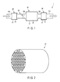
- FIG. 1 is a view schematically showing an exhaust gas-purifying system according to an embodiment of the present invention.
- FIG. 2 is a perspective view showing an example of a diesel oxidation catalyst that can be used in the exhaust gas-purifying system shown in FIG. 1 .
- FIG. 3 is an enlarged sectional view showing a part of the diesel oxidation catalyst shown in FIG. 2 .
- FIG. 4 is a sectional view showing an example of a diesel particulate filter that can be used in the exhaust gas-purifying system shown in FIG. 1 .
- FIG. 5 is a sectional view showing an example of an ammonia slip catalyst that can be used in the exhaust gas-purifying system shown in FIG. 1 .
- FIG. 6 is an enlarged sectional view showing a part of the ammonia slip catalyst shown in FIG. 5 . Note that the arrow outline with a blank inside indicates a flow direction of exhaust gas.
- the exhaust gas-purifying system 1 shown in FIG. 1 is an exhaust gas-purifying system that purifies exhaust gas discharged from a diesel engine (not shown).
- the exhaust gas-purifying system 1 includes catalytic converters 20, 30 and 40 connected in series between the diesel engine and a tail pipe (not shown).
- the catalytic converter 20 includes a converter body 21 and a diesel oxidation catalyst 22.
- the converter body 21 is made of, for example, metal or alloy.
- the converter body 21 has a hollow structure provided with inlet and outlet ports.
- the inlet port of the converter body 21 is connected to piston chambers of the diesel engine via a pipe 10a and an exhaust manifold (not shown).
- the outlet port of the converter body 21 is connected to an end of a pipe 10b.
- the diesel oxidation catalyst 22 is a monolith catalyst of straight flow type.
- the diesel oxidation catalyst 22 is contained in the converter body 21 such that the exhaust gas supplied from the pipe 10a to the catalytic converter 20 passes through the through-holes of the diesel oxidation catalyst 22 and then discharged into the pipe 10b.
- the diesel oxidation catalyst 22 promotes oxidation of carbon monoxide and hydrocarbons.
- CO and HC concentrations of the exhaust gas are lowered, and the particulate matter made of high-boiling hydrocarbons or sulfides is partially removed from the exhaust gas.
- the diesel oxidation catalyst 22 includes a monolith honeycomb substrate 221 and a catalytic layer 222.
- the monolith honeycomb substrate 221 is a column provided with through-holes each extending from one of the bases to the other of the bases.
- the monolith honeycomb substrate 221 is made of, for example, ceramics such as cordierite and silicon carbide.
- the catalytic layer 222 is formed on the partition walls of the monolith honeycomb substrate 221.
- the catalytic layer 222 may have a single-layer structure or a multi-layer structure.
- the catalytic layer 222 includes, for example, a first precious metal element and a first carrier.
- the first precious metal element is, for example, an element of platinum group such as platinum and palladium.
- the catalytic layer 222 may includes only a single precious metal element or a plurality of precious metal elements as the first precious metal element.
- the first carrier carries the first precious metal element.
- the first carrier is particles made of a refractory material such as alumina.
- the first carrier increases the surface area of the precious metal and dissipates the heat generated by the catalytic reaction so as to suppress sintering of the precious metal.
- the catalytic converter 30 includes a converter body 31 and a diesel particulate filter 32.
- the converter body 31 is made of, for example, metal or alloy.
- the converter body 31 has a hollow structure provided with inlet and outlet ports.
- the inlet port of the converter body 31 is connected to the outlet port of the converter body 21 via the pipe 10b.
- the outlet port of the converter body 31 is connected to an end of a pipe 10c.
- the pipe 10b is provided with an injector 50 for injecting ammonia or a precursor thereof, for example, aqueous urea into the exhaust gas flowing in the pipe 10b.
- the diesel particulate filter 32 is a monolith catalyst of wall flow type.
- the diesel particulate filter 32 is contained in the converter body 31 such that the exhaust gas supplied from the pipe 10b to the catalytic converter 30 passes through the partition walls of the diesel particulate filter 32 and then discharged into the pipe 10c.
- the diesel particulate filter 32 removes the remainder of the particulate matter from the exhaust gas.
- the diesel particulate filter 32 includes a monolith honeycomb substrate 321 and an active component (not shown).
- the monolith honeycomb substrate 321 includes a honeycomb structure 3211 and plugs 3212a and 3212b.
- the honeycomb structure 3211 is a column provided with through-holes each extending from one of the bases to the other of the bases.
- the honeycomb structure includes porous partition walls. The porous partition walls allow the exhaust gas to pass through without allowing almost the whole particulate matter carried by the exhaust gas to pass therethrough.
- honeycomb structure 3211 As a material of the honeycomb structure 3211, for example, ceramics such as cordierite and silicon carbide can be used. A nonwoven fabric made of metal may be incorporated in the honeycomb structure 3211.
- the plugs 3212a plug some of the holes of the honeycomb structure 3211 at the downstream side.
- the plugs 3212b plug the remainder of the holes of the honeycomb structure 3211 at the upstream side.
- upstream side used herein means the end surface of the honeycomb structure to which the exhaust gas is supplied.
- downstream side used herein means the end surface of the honeycomb structure from which the exhaust gas is discharged.
- the plugs 3212a and 3212b are arranged such that the hole plugged with the plug 3212a and the hole plugged with the plug 3212b are adjacent to each other with the porous partition wall interposed therebetween and the plugs 3212b are positioned on the upstream side with respect to the plugs 3212a.
- the plugs 3212a are arranged on the downstream side of the honeycomb structure 3211, the plugs 3212a may be arranged at positions spaced apart from the downstream side of the honeycomb structure 3211.
- the plugs 3212b are arranged on the upstream side of the honeycomb structure 3211, the plugs 3212b may be arranged at positions spaced apart from the upstream side of the honeycomb structure 3211.
- ceramics such as cordierite and silicon carbide can be used.
- the plugs 3212a and the porous partition walls form upstream cells 3213a that open on the upstream side.
- the plugs 3212b and the porous partition walls form downstream cells 3213b that open on the downstream side.
- the upstream cell 3213a and the downstream cell 3213b are adjacent to each other with the porous partition wall interposed therebetween.
- the active component is supported by the filter substrate 321, in particular, the honeycomb structure 32211.
- the active component is a component that exhibits a catalytic activity for the selective catalytic reduction, in other words, a component that promotes the reaction between nitrogen oxides and ammonia.
- the following formula (1) represents the reaction between water and urea that can be used as the ammonia precursor.
- the following formulae (2) and (3) represent examples of reaction between nitrogen oxides and ammonia.
- active components that are generally used in the selective catalytic reduction may be used.
- zeolite whose metal ions, in particular, alkali metal ions such as sodium ions and potassium ions are partially exchanged with transition metal ions such as iron ions and copper ions may be used as the active component.
- titanium, tungsten, vanadium, zirconium or cerium may be used as the active component.
- the zeolite-based active component has a high ability in adsorbing ammonia.
- the ammonia slip can be effectively suppressed by monitoring the adsorption amount and temperature and appropriately controlling desorption of ammonia.
- fuel is discontinuously or continuously sprayed onto the diesel particulate filter 32 to burn off the particulate matter deposited on the filter.
- the active component is subjected to high temperatures.
- the ammonia slip catalyst 42 to be described in detail needs a higher ability in purifying ammonia.
- a composite oxide containing zirconia Although an ability of a composite oxide containing zirconia to adsorb ammonia is lower than that of zeolite, it has a higher heat resistance.
- a composite oxide containing at least one element selected from the group consisting of aluminum, silicon, titanium, cerium and tungsten in addition to zirconium exhibits a high heat resistance and a high catalytic activity for the selective catalytic reduction.
- a composite oxide containing zirconium and cerium in particular, a composite oxide containing zirconium, cerium, tungsten and optionally at least one element selected from the group consisting of silicon, titanium, neodymium and yttrium exhibits a high heat resistance and a high catalytic activity for the selective catalytic reduction.
- a composite oxide is used as the active component, a high NO x -purifying ability can be achieved and reduction in the abilities of promoting selective catalytic reduction and adsorbing ammonia when subjected to high
- a mass ratio of zirconia in this composite oxide which is obtained assuming that the whole zirconium in this composite oxide is in the form of zirconia, is, for example, within a range of 20% to 70% by mass, and typically within a range of 40% to 70% by mass.
- a mass ratio of ceria in this composite oxide which is obtained assuming that the whole cerium in this composite oxide is in the form of ceria, is, for example, within a range of 5% to 50% by mass, and typically within a range of 10% to 30% by mass.
- a mass ratio of tungsten (VI) oxide in the composite oxide which is obtained assuming that the whole tungsten in this composite oxide is in the form of tungsten oxide (VI), is, for example, within a range of 5% to 20% by mass, and typically within a range of 8% to 15% by mass.
- Silicon suppresses the poisoning of the active component caused by sulfur.
- a mass ratio of silica in the composite oxide which is obtained assuming that the whole silicon in this composite oxide is in the form of silica, is, for example, within a range of 1% to 10% by mass.
- Titanium suppresses the poisoning of the active component caused by sulfur and increases the heat resistance.
- a mass ratio of titania in the composite oxide which is obtained assuming that the whole titanium in this composite oxide is in the form of titania, is, for example, within a range of 1% to 5% by mass.
- Neodymium and yttrium increase the stability of zirconium and thus improve the durability of the active component.
- a mass ratio of neodymium oxide in the composite oxide which is obtained assuming that the whole neodymium in this composite oxide is in the form of neodymium oxide, is, for example, within a range of 1% to 5% by mass.
- a mass ratio of yttria in the composite oxide which is obtained assuming that the whole yttrium in this composite oxide is in the form of yttria, is, for example, within a range of 1% to 5% by mass.
- a ratio of total amount of them to the amount of the composite oxide is, for example, within a range of 1% to 15% by mass.
- the diesel particulate filter 32 can further contains alumina.
- Alumina is supported by the filter substrate 321, in particular, the honeycomb structure 321.
- Alumina improves the heat resistance of the diesel particulate filter 32.
- a ratio of the amount of alumina to the total amount of the composite oxide and alumina is, for example, within a range of 5% to 30% by mass, and typically within a range of 10% to 20% by mass.
- the catalytic converter 40 includes a converter body 41 and an ammonia slip catalyst 42.
- the converter body 41 is made of, for example, metal or alloy.
- the converter body 41 has a hollow structure provided with inlet and outlet ports.
- the inlet port of the converter body 41 is connected to the outlet port of the converter body 31 via the pipe 10c.
- the outlet port of the converter body 41 is connected to an end of a pipe 10d.
- the ammonia slip catalyst 42 is a monolith catalyst of straight flow type.
- the ammonia slip catalyst 42 is contained in the converter body 41 such that the exhaust gas supplied from the pipe 10c to the catalytic converter 40 passes through the through-holes of the ammonia slip catalyst 42 and then discharged into the pipe 10d.
- the ammonia slip catalyst 42 is an oxidation catalyst and promotes oxidation of unreacted ammonia discharged from the diesel particulate filter 32. Although oxidation of ammonia produces nitrogen oxides, the amount of nitrogen oxides produced in the ammonia slip catalyst 42 is small because the amount of the unreacted ammonia discharged from the diesel particulate filter 32 is small, too. Thus, the ammonia slip catalyst 42 decreases the ammonia concentration of the exhaust gas without greatly increasing the nitrogen oxides concentration of the exhaust gas.
- the ammonia slip catalyst 42 includes a monolith honeycomb substrate 421 and a catalytic layer 422.
- the monolith honeycomb substrate 421 is a column provided with through-holes each extending from one of the bases to the other of the bases.
- the monolith honeycomb substrate 421 is made of, for example, ceramics such as cordierite and silicon carbide.
- a metallic honeycomb substrate may be used as the substrate 421.
- the catalytic layer 422 is formed on the partition walls of the monolith honeycomb substrate 421.
- the catalytic layer 422 may have a single-layer structure or a multi-layer structure.
- the catalytic layer 422 includes, for example, a second precious metal element and a second carrier.
- the second precious metal element is, for example, an element of platinum group such as platinum and palladium and typically contains platinum.
- the second precious metal element promotes oxidation of ammonia.
- the catalytic layer 422 may includes only a single precious metal element or a plurality of precious metal elements as the second precious metal element.
- the catalytic layer 422 may contain only platinum or platinum and palladium as the second precious metal element.
- use of palladium may degrade the ability of the ammonia slip catalyst 42 to oxidize ammonia.
- a proportion of palladium in the second precious metal element is, for example, 30% or 20% by mass or less, and typically 10% by mass or less.
- a mass of the second precious metal element per 1 L of volumetric capacity of the ammonia slip catalyst 42 is, for example, within a range of 0.1 to 2.0 g/L, and typically within a range of 0.3 to 0.8 g/L.
- the second precious metal element can be omitted.
- the second carrier carries the second precious metal element.
- the second carrier is particles made of a refractory material such as alumina.
- the second carrier increases the surface area of the precious metal and dissipates the heat generated by the catalytic reaction so as to suppress sintering of the precious metal.
- the second carrier can be omitted.
- the catalytic layer 422 further includes zeolite whose alkali metal ion such sodium ion and potassium ion is partially exchanged with a transition metal ion.
- the zeolite is, for example, one or more of BEA, MFI, FER, MOR, CHA and ZSM5 zeolites.
- the zeolite is at least one of BEA and MFI zeolites or at least one of BEA, CHA and ZSM5 zeolites.
- the transition metal ion is, for example, one or more of iron, copper, silver and platinum ions, and typically at least one of iron and copper ions.
- used as the transition metal ion is, for example, at least one of copper and iron ions, and preferably copper ion.
- used as the transition metal ion is, for example, at least one of copper and iron ions.
- used as the transition metal ion is, for example, at least one of copper and iron ions.
- ZSM5 used as the transition metal ion is, for example, at least one of copper and iron ions.
- Such a zeolite has high abilities of adsorbing ammonia and promoting the reaction between nitrogen oxides and ammonia. Thus, even in the case where the ammonia concentration in the exhaust gas exceeds the purification capacity of the ammonia slip catalyst 42, the zeolite can adsorb excess ammonia. At least a part of ammonia adsorbed by the zeolite can be used for purifying nitrogen oxides.
- ammonia concentration of the exhaust gas discharged from the ammonia slip catalyst 42 can be decreased. Further, in this case, NO x -purifying ability of the exhaust gas-purification system 1 is improved.
- the diesel particulate filter 32 has a function of a common diesel particulate filter and a function of a selective catalytic reduction catalyst. Therefore, this exhaust gas-purifying system 1 can be installed in a relatively small space.
- a zeolite having a high ability of adsorbing ammonia and a high ability of promoting the reaction between nitrogen oxides and ammonia is used in the catalytic layer 422. Although such a zeolite is generally low in heat resistance, the ammonia slip catalyst 42 is not subjected to high temperatures as compared with the diesel particulate filter 32. Therefore, the exhaust gas-purifying system 1 is less prone to cause performance degradation.
- a ratio of the volumetric capacity of the diesel particulate filter 32 to the volumetric capacity of the ammonia slip catalyst 42 is, for example, within a range of 1 to 5. In the case where this ratio is small, it is difficult to sufficiently decrease NO x concentration of the exhaust gas. In the case where this ratio is large, it is difficult to sufficiently decrease ammonia concentration of the exhaust gas.
- an amount of the active component per 1 L of the volumetric capacity of the diesel particulate filter 32 is, for example, within a range of 40 to 210 g/L, and typically within a range of 60 to 150 g/L.
- an amount of the active component per 1 L of the volumetric capacity of the diesel particulate filter 32 is, for example, within a range of 40 to 180 g/L, and typically, within a range of 60 to 100g/L.
- an amount of the active component is small, a high NO x -purifying performance cannot be achieved.
- an amount of the active component is large, the cost increases and the heat capacity of the diesel particulate filter 32 and the pressure loss of the exhaust gas increase. Consequently, the exhaust pressure of the system increases and the fuel efficiency is degraded.
- An amount of zeolite per 1 L of volumetric capacity of the ammonia slip catalyst 42 is, for example, within a range of 10 to 300 g/L, and typically within a range of 120 to 210 g/L.
- a mass of CHA per 1 L of volumetric capacity of the ammonia slip catalyst 42 is, for example, within a range of 60 to 200 g/L, and typically within a range of 80 to 140 g/L.
- a mass of BEA per 1 L of volumetric capacity of the ammonia slip catalyst 42 is, for example, within a range of 80 to 200 g/L, and typically within a range of 100 to 160 g/L.
- a mass of ZSM-5 per 1 L of volumetric capacity of the ammonia slip catalyst 42 is, for example, within a range of 80 to 200 g/L, and typically within a range of 100 to 160 g/L.
- an amount of the zeolite is small, ammonia concentration of the exhaust gas cannot be decreased sufficiently.
- an amount of the zeolite is large, the cost and the heat capacity of the ammonia slip catalyst 42 increase. Consequently, when an amount of the zeolite exceeds a certain value, almost no improvement in the performance is achieved even when the amount of the zeolite is further increased.
- a mass ratio of the zeolite in the diesel particulate filter 32 to the zeolite in the ammonia slip catalyst 42 is, for example, 2 or less, and typically zero. Decreasing this ratio results in improvement in the durability of the exhaust gas-purifying system 1.
- FIG. 1 shows three catalytic converters 20, 30 and 40.
- a single catalytic converter may be used instead of the catalytic converters 30 and 40. That is, the diesel particulate filter 32 and the ammonia slip catalyst 42 may be arranged in a single converter body. In this case, the diesel particulate filter 32 and the ammonia slip catalyst 42 may be spaced apart from each other or may be integrated into one piece.
- the catalytic layer 222 of the diesel oxidation catalyst 22 can contain an element of platinum group other than platinum and palladium instead of or in addition to platinum and palladium.
- the catalytic layer 222 may contain a transition metal element other than elements of platinum group instead of or in addition to elements of platinum group.
- the catalytic layer 222 can contain one or more of platinum, palladium, rhodium, ruthenium, iridium and cobalt.
- the filter substrate 321 of the diesel particulate filter 32 may further support a component other then the above-described active component.
- the filter substrate 321, in particular, the honeycomb structure 3211 may further support one or more of platinum, palladium, rhodium, ruthenium, iridium and cobalt.
- the catalytic layer 422 of the ammonia slip catalyst 42 can include an element of platinum group other than platinum and palladium instead of or in addition to platinum and palladium.
- the catalytic layer 422 may contain a transition metal element other than elements of platinum group instead of or in addition to elements of platinum group.
- the catalytic layer 422 can contain one or more of platinum, palladium, rhodium, ruthenium, iridium and cobalt.
- the diesel oxidation catalyst 22 described with reference to FIGS. 1 to 3 was manufactured by the following method.
- alumina powder 70 g of alumina powder, 100 g of zeolite powder, 200 g of alumina sol containing alumina at a concentration of 10% by mass, and 200 g of deionized water were mixed together to prepare slurry.
- a monolith honeycomb substrate 221 having a volumetric capacity of 1.4 L was coated with the slurry.
- the coated film was dried at 250°C for 1 hour, and was subjected to a heat treatment at 500°C for 1 hour.
- the substrate 221 was immersed in an aqueous solution containing platinum and then immersed in an aqueous solution containing palladium so as to load the coated layer on the substrate 221 with 2.8 g of platinum and 1.4 g of palladium.
- the structure was subjected to a heat treatment at 250°C for 1 hour.
- the diesel particulate filter 32 described with reference to FIGS. 1 to 4 was manufactured by the following method.
- oxide powder containing zirconium 90 g of oxide powder containing zirconium, 200 g of alumina sol containing alumina in a concentration of 10% by mass, and 300 g of deionized water were mixed together to prepare slurry.
- oxide powder containing zirconium used herein was oxide powder containing titanium, silicon, tungsten and cerium in addition to zirconium.
- a mass ratio of zirconium converted into that of zirconia was 51.0% by mass
- a mass ratio of titanium converted into that of titania was 3% by mass
- a mass ratio of silicon converted into that of silica was 2.3% by mass
- a mass ratio of tungsten converted into that of tungsten (VI) oxide was 8.5% by mass
- a mass ratio of cerium converted into that of ceria was 16.3% by mass.
- a filter substrate 321 having a volumetric capacity of 3.0 L and made of cordierite was coated with the slurry.
- the coated film was dried at 250°C for 1 hour, and was subjected to a heat treatment at 500°C for 1 hour.
- filter DPF1 The diesel particulate filter 32 described with reference to FIGS. 1 to 4 was thus completed.
- the diesel particulate filter thus obtained is referred to as "filter DPF1".
- the diesel particulate filter 32 described with reference to FIGS. 1 to 4 was manufactured by the same method as described for the filter DPF1 except that FeZSM5 powder was used instead of the oxide powder containing zirconium.
- filter DPF2 the diesel particulate filter thus obtained is referred to as "filter DPF2".
- the diesel particulate filter 32 described with reference to FIGS. 1 to 4 was manufactured by the same method as described for the filter DPF1 except that CuCHA powder was used instead of the oxide powder containing zirconium.
- filter DPF3 the diesel particulate filter thus obtained is referred to as "filter DPF3".
- the diesel particulate filter 32 described with reference to FIGS. 1 to 4 was manufactured by the following method.
- alumina powder 90 g of alumina powder, 200 g of alumina sol containing alumina in a concentration of 10% by mass, and 300 g of deionized water were mixed together to prepare slurry.
- a filter substrate 321 having a volumetric capacity of 3.0 L and made of cordierite was coated with the slurry.
- the coated film was dried at 250°C for 1 hour, and was subjected to a heat treatment at 500°C for 1 hour.
- the filter substrate 321 was immersed in an aqueous solution containing platinum, and subsequently immersed in an aqueous solution containing palladium so as to load the coated layer on the filter substrate 321 with 1.8 g of platinum and 0.9 g of palladium.
- filter DPF4 The diesel particulate filter 32 described with reference to FIGS. 1 to 4 was thus completed.
- the diesel particulate filter thus obtained is referred to as "filter DPF4".
- a selective catalytic reduction catalyst was manufactured by the following method.
- zeolite 160 g of zeolite, 200 g of alumina sol containing alumina in a concentration of 10% by mass, and 250 g of deionized water were mixed together to prepare slurry.
- the zeolite used herein was FeZSM5.
- a monolith honeycomb substrate having a volumetric capacity of 3.0 L was coated with the slurry.
- the coated film was dried at 250°C for 1 hour, and then subjected to a heat treatment at 500°C for 1 hour.
- the ammonia slip catalyst 42 described with reference to FIGS. 1 , 5 and 6 was manufactured by the following method.
- zeolite 150 g of zeolite, 30 g of alumina powder, 200 g of alumina sol containing alumina in a concentration of 10% by mass, and 250 g of deionized water mixed together to prepare slurry.
- the zeolite used herein was FeZSM5.
- a monolith honeycomb substrate 421 having a volumetric capacity of 1.0 L was coated with the slurry.
- the coated film was dried at 250°C for 1 hour, and then subjected to a heat treatment at 500°C for 1 hour.
- the substrate 421 was immersed in an aqueous solution containing platinum and then immersed in an aqueous solution containing palladium so as to load the coated layer on the substrate 421 with 0.6 g of platinum and 0.3 g of palladium.
- the structure was subjected to a heat treatment at 250°C for 1 hour.
- catalyst ASC1 The ammonia slip catalyst 42 described with reference to FIGS. 1 , 5 and 6 was thus completed.
- the ammonia slip catalyst thus obtained is referred to as "catalyst ASC1".
- catalyst ASC2 180 g of alumina powder, 200 g of alumina sol containing alumina in a concentration of 10% by mass, and 250 g of deionized water were mixed together to prepare slurry.
- An ammonia slip catalyst was manufactured by the same method as that described for the catalyst ASC1 except that the coated layer was formed using this slurry.
- the ammonia slip catalyst thus obtained is referred to as "catalyst ASC2".
- the ammonia slip catalyst 42 described with reference to FIGS. 1 , 5 and 6 was manufactured by the following method.
- zeolite 150 g of zeolite, 30 g of alumina powder, 200 g of alumina sol containing aluminum in a concentration of 10% by mass, and 250 g of deionized water were mixed together to prepare slurry.
- the zeolite used herein was a mixture of 70 g of CuCHA, 40 g of FeBEA, and 40 g of FeZSM5.
- a monolith honeycomb substrate 421 having a volumetric capacity of 1.0 L was coated with the slurry.
- the coated film was dried at 250°C for 1 hour, and then subjected to a heat treatment at 500°C for 1 hour.
- the substrate 421 was immersed in an aqueous solution containing platinum so as to load the coated layer on the substrate 421 with 0.5 g of platinum.
- the structure was subjected to a heat treatment at 250°C for 1 hour.
- ammonia slip catalyst 42 described with reference to FIGS. 1 , 5 and 6 was thus completed.
- the ammonia slip catalyst thus obtained is referred to as "catalyst ASC3".
- the exhaust gas-purifying system 1 shown in FIG. 1 was assembled. Specifically, the catalyst DOC was used as the diesel oxidation catalyst 21. As the diesel particulate filter 32, the filter DPF1 was used. As the ammonia slip catalyst 42, the catalyst ASC1 was used.
- purifying system PS1 the exhaust gas-purifying system thus obtained is referred to as "purifying system PS1".
- purifying system PS2 The same exhaust gas-purifying system as the purifying system PS1 was manufactured except that the catalyst ASC2 was used instead of the catalyst ASC1.
- purifying system PS2 the exhaust gas-purifying system thus obtained is referred to as "purifying system PS2".
- purifying system PS3 The same exhaust gas-purifying system as the purifying system PS1 was manufactured except that the filter DPF2 was used instead of the filter DPF1.
- purifying system PS3 the exhaust gas-purifying system thus obtained is referred to as "purifying system PS3".
- purifying system PS4 The same exhaust gas-purifying system as the purifying system PS1 was manufactured except that the catalyst ASC2 was used instead of the catalyst ASC1.
- the exhaust gas-purifying system thus obtained is referred to as "purifying system PS4".
- purifying system PS5 The same exhaust gas-purifying system as the purifying system PS1 was manufactured except that the filter DPF3 was used instead of the filter DPF1.
- purifying system PS5 the exhaust gas-purifying system thus obtained is referred to as "purifying system PS5".
- FIG. 9 is a view schematically showing an exhaust gas-purifying system according to a comparative example.
- the exhaust gas-purifying system 1 shown in FIG. 9 is an exhaust gas-purifying system for purifying exhaust gas discharged from a diesel engine (not shown).
- the exhaust gas-purifying system 1 includes catalytic converters 20, 30a, 30b and 40' connected in series between the diesel engine and the tail pipe.
- the catalytic converter 30a includes a converter body 31a and a diesel particulate filter 32a.
- the converter body 31a is made of, for example, metal or alloy.
- the converter body 31a has a hollow structure provided with inlet and outlet ports.
- the inlet port of the converter body 31a is connected to the outlet port of the converter body 21 via the pipe 10b.
- the outlet port of the converter body 31a is connected to an end of a pipe 10e.
- an injector 50 for injecting ammonia or a precursor thereof into the exhaust gas is provided not to the pipe 10b but to the pipe 10e.
- the diesel particulate filter 32a is a monolith catalyst of wall flow type.
- the diesel particulate filter 32a is contained in the converter body 31a such that the exhaust gas supplied from the pipe 10b to the catalytic converter 30a passes through the partition walls of the diesel particulate filter 32a and then discharged into the pipe 10e.
- the diesel particulate filter 32a includes the same filter substrate as that described with reference to FIG. 4 .
- the diesel particulate filter 32a removes particulate matter from the exhaust gas.
- the catalytic converter 30b includes a converter body 31b and a selective catalytic reduction catalyst 32b.
- the converter body 31b is made of, for example, metal or alloy.
- the converter body 31b has a hollow structure provided with inlet and outlet ports.
- the inlet port of the converter body 31b is connected to the outlet port of the converter body 31a via the pipe 10e.
- the outlet port of the converter body 31b is connected to an end of a pipe 10c.
- the selective catalytic reduction catalyst 32b is a monolith catalyst of straight flow type.
- the selective catalytic reduction catalyst 32b is contained in the converter body 31b such that the exhaust gas supplied from the pipe 10e to the catalytic converter 30b passes through the through-holes of the selective catalytic reduction catalyst 32b and then discharged into the pipe 10c.
- the selective catalytic reduction catalyst 32b includes a monolith honeycomb substrate and a catalytic layer formed on the partition walls thereof. The selective catalytic reduction catalyst 32b promotes the reaction between nitrogen oxides and ammonia.
- the catalytic converter 40' includes a converter body 41' and an ammonia slip catalyst 42'.
- the converter body 41' is made of, for example, metal or alloy.
- the converter body 41' has a hollow structure provided with inlet and outlet ports.
- the inlet port of the converter body 41' is connected to the outlet port of the converter body 31b via the pipe 10c.
- the outlet port of the converter body 41' is connected to an end of a pipe 10d.
- the ammonia slip catalyst 42' is a monolith catalyst of straight flow type.
- the ammonia slip catalyst 42' is contained in the converter body 41' such that the exhaust gas supplied from the pipe 10c to the catalytic converter 40' passes through the through-holes of the ammonia slip catalyst 42' and then discharged into the pipe 10d.
- the ammonia slip catalyst 42' includes a monolith honeycomb substrate and a catalytic layer formed on the partition walls thereof. The ammonia slip catalyst 42' promotes oxidation of unreacted ammonia discharged from the selective catalytic reduction catalyst 32b.
- This exhaust gas-purifying system 1 was assembled. Specifically, the catalyst DOC was used as the diesel oxidation catalyst 21. As the diesel particulate filter 32a, the filter DPF4 was used. As the selective catalytic reduction catalyst 32b, the catalyst SCR was used. As the ammonia slip catalyst 42, the catalyst ASC2 was used.
- purifying system PS6 the exhaust gas-purifying system thus obtained is referred to as "purifying system PS6".
- purifying system PS7 The same exhaust gas-purifying system as the purifying system PS1 was assembled except that the catalyst ASC3 was used instead of the catalyst ASC1.
- purifying system PS7 the exhaust gas-purifying system thus obtained is referred to as "purifying system PS7".
- each of the purifying system PS1 to PS7 was mounted on an exhaust system for an engine with a piston displacement of 2.2 L, and the engine was driven under normal operating conditions. Under the operating conditions, the engine RPM was set at 2000 rpm and the torque was set at 170 Nm so as to keep the NO x concentration of the exhaust gas supplied to the purifying system at 250 ppm.
- the injection of aqueous urea using the injector 50 was performed such that the injection amount of urea is 0,75 times the amount of NO x (converted into an amount of urea) contained in the exhaust gas supplied to the purifying system.
- gas-analyzing apparatus were arranged upstream and downstream of each purifying system to measure the NO x concentration of the exhaust gas.
- FIG. 7 is a graph showing an example of performance of exhaust gas-purifying systems regarding ammonia slip and NO x -purification.
- FIG. 8 is a graph showing an example of initial and post-endurance performance of exhaust gas-purifying systems regarding NO x -purification.
- the abscissa represents the ammonia concentration of the exhaust gas discharged from the exhaust gas-purifying system.
- the purifying system PS1 is slightly inferior to the purifying system PS6 in an ability to purify ammonia
- the former has a higher ability to purify NO x than the latter.
- the purifying system PS2 has a slightly higher ability to purify NO x than the purifying system PS6, the ability of the former to purify ammonia is greatly lower than that of latter.
- the purifying system PS3 is slightly inferior to the purifying system PS6 in an ability to purify NO x , the former has a higher ability to purify ammonia than the latter.
- the purifying system PS4 has a lower ability to purify ammonia and a much lower ability to purify ammonia than the purifying system PS6.
- the purifying system PS5 has a higher ability to purify ammonia and a higher ability to purify ammonia than the purifying system PS6.
- the purifying system PS7 has a slightly lower ability to purify ammonia than the purifying system PS6, the ability of the former to purify NO x is higher than that of latter.
- the purifying systems PS1, PS3, PS5 and PS7 can replace the purifying system PS6.
- the purifying systems PS1, PS5 and PS7 achieved almost the same or more than the ability of the purifying system PS6 to purify ammonia and further achieved a higher ability to purify NO x than the purifying system PS6, that is, the purifying systems PS1, PS5 and PS7 offered excellent performance.
- the performance degradation is suppressed in the purifying system PS1 as compared with the purifying system PS4.
- the data in FIGS. 7 and 8 it is considered that decreasing the amount of zeolite in the diesel particulate filter improves the durability.
Landscapes
- Chemical & Material Sciences (AREA)
- Engineering & Computer Science (AREA)
- Chemical Kinetics & Catalysis (AREA)
- Materials Engineering (AREA)
- Organic Chemistry (AREA)
- Combustion & Propulsion (AREA)
- Crystallography & Structural Chemistry (AREA)
- Health & Medical Sciences (AREA)
- Biomedical Technology (AREA)
- Environmental & Geological Engineering (AREA)
- Analytical Chemistry (AREA)
- General Chemical & Material Sciences (AREA)
- Oil, Petroleum & Natural Gas (AREA)
- General Engineering & Computer Science (AREA)
- Mechanical Engineering (AREA)
- Toxicology (AREA)
- Exhaust Gas After Treatment (AREA)
- Exhaust Gas Treatment By Means Of Catalyst (AREA)
- Catalysts (AREA)
Applications Claiming Priority (2)
| Application Number | Priority Date | Filing Date | Title |
|---|---|---|---|
| JP2010073381 | 2010-03-26 | ||
| PCT/JP2011/057375 WO2011118777A1 (fr) | 2010-03-26 | 2011-03-25 | Système d'épuration des gaz d'échappement |
Publications (2)
| Publication Number | Publication Date |
|---|---|
| EP2554809A1 true EP2554809A1 (fr) | 2013-02-06 |
| EP2554809A4 EP2554809A4 (fr) | 2014-11-26 |
Family
ID=44673317
Family Applications (1)
| Application Number | Title | Priority Date | Filing Date |
|---|---|---|---|
| EP11759581.9A Withdrawn EP2554809A4 (fr) | 2010-03-26 | 2011-03-25 | Système d'épuration des gaz d'échappement |
Country Status (5)
| Country | Link |
|---|---|
| US (1) | US8679412B2 (fr) |
| EP (1) | EP2554809A4 (fr) |
| JP (1) | JP5771599B2 (fr) |
| CN (1) | CN102822460B (fr) |
| WO (1) | WO2011118777A1 (fr) |
Cited By (6)
| Publication number | Priority date | Publication date | Assignee | Title |
|---|---|---|---|---|
| FR3041032A1 (fr) * | 2015-09-14 | 2017-03-17 | Peugeot Citroen Automobiles Sa | Dispositif de post-traitement des gaz d’echappement d’un moteur a combustion |
| FR3042813A1 (fr) * | 2015-10-27 | 2017-04-28 | Peugeot Citroen Automobiles Sa | Dispositif de post-traitement des gaz d’echappement d’un moteur a combustion |
| EP2555866B1 (fr) * | 2010-04-08 | 2019-10-09 | Basf Se | Catalyseur comprenant les zéolithes Cu-CHA et Fe-MFI et procédé DE TRAITEMENT DE NOX DANS DES COURANTS GAZEUX |
| EP3219387B1 (fr) * | 2014-11-12 | 2020-07-08 | Hitachi Zosen Corporation | Méthode pour décomposer un aldheyde présent dans des gaz d'échappement |
| GB2547873B (en) * | 2014-12-31 | 2021-03-10 | Cummins Emission Solutions Inc | Close coupled single module aftertreatment system |
| US11141696B2 (en) | 2014-12-31 | 2021-10-12 | Cummins Emission Solutions, Inc. | Single module integrated aftertreatment module |
Families Citing this family (15)
| Publication number | Priority date | Publication date | Assignee | Title |
|---|---|---|---|---|
| US8101146B2 (en) * | 2011-04-08 | 2012-01-24 | Johnson Matthey Public Limited Company | Catalysts for the reduction of ammonia emission from rich-burn exhaust |
| US9999877B2 (en) | 2011-10-05 | 2018-06-19 | Basf Se | Cu-CHA/Fe-BEA mixed zeolite catalyst and process for the treatment of NOx in gas streams |
| CN104066508B (zh) * | 2011-10-05 | 2018-02-06 | 巴斯夫欧洲公司 | Cu‑CHA/Fe‑BEA混合沸石催化剂和处理气流中的NOX的方法 |
| JP5810846B2 (ja) * | 2011-11-04 | 2015-11-11 | 東ソー株式会社 | 銅及びアルカリ金属を有するチャバザイト型ゼオライトの製造方法 |
| CN102658118A (zh) * | 2012-01-19 | 2012-09-12 | 中国汽车技术研究中心 | 一种环境友好NOx选择性催化还原催化剂及制备方法 |
| JP2014061456A (ja) * | 2012-09-19 | 2014-04-10 | Cataler Corp | 排気ガス浄化用フィルター |
| CN109590018B (zh) * | 2013-03-15 | 2022-06-03 | 庄信万丰股份有限公司 | 用于处理废气的催化剂 |
| JP6326580B2 (ja) * | 2013-04-24 | 2018-05-23 | 株式会社 Acr | NOx還元触媒手段を備えた排気ガス浄化装置 |
| KR101522857B1 (ko) * | 2013-05-02 | 2015-05-26 | 희성촉매 주식회사 | 복합형 선택적 환원 촉매 |
| JP2016079912A (ja) * | 2014-10-17 | 2016-05-16 | マツダ株式会社 | 排気ガス浄化装置及び浄化方法 |
| JP6443501B1 (ja) | 2017-06-23 | 2018-12-26 | マツダ株式会社 | 排気ガス浄化システム |
| DE102017006059A1 (de) * | 2017-06-27 | 2018-12-27 | Daimler Ag | Abgasanlage für einen Kraftwagen |
| CN113164874B (zh) | 2019-03-26 | 2023-01-10 | 日本瑞翁株式会社 | 沸石膜复合体、以及使用它的支链二烯烃的分离方法和制造方法 |
| EP3972723B1 (fr) | 2019-05-21 | 2025-10-15 | BASF Mobile Emissions Catalysts LLC | Catalyseur d'oxydation d'ammoniac pour des applications diesel |
| JP7581556B1 (ja) | 2024-06-18 | 2024-11-12 | 株式会社三井E&S | アンモニアの燃焼排ガスの処理システム |
Family Cites Families (19)
| Publication number | Priority date | Publication date | Assignee | Title |
|---|---|---|---|---|
| US5260035A (en) * | 1992-08-05 | 1993-11-09 | Corning Incorporated | Apparatus and method for modifying gaseous mixtures |
| JP3513536B2 (ja) * | 1995-01-27 | 2004-03-31 | トヨタ自動車株式会社 | 排気浄化方法及び排気浄化装置 |
| JP3552649B2 (ja) * | 1999-06-23 | 2004-08-11 | トヨタ自動車株式会社 | 内燃機関の排気浄化装置 |
| JP2002089327A (ja) * | 2000-09-14 | 2002-03-27 | Nissan Motor Co Ltd | 内燃機関の排気浄化装置 |
| DE10054877A1 (de) * | 2000-11-06 | 2002-05-29 | Omg Ag & Co Kg | Abgasreinigungsanlage für die selektive katalytische Reduktion von Stickoxiden unter mageren Abgasbedingungen und Verfahren zur Abgasreinigung |
| JP2004060494A (ja) * | 2002-07-26 | 2004-02-26 | Toyota Motor Corp | 内燃機関の排気浄化装置 |
| DE10308288B4 (de) * | 2003-02-26 | 2006-09-28 | Umicore Ag & Co. Kg | Verfahren zur Entfernung von Stickoxiden aus dem Abgas eines mager betriebenen Verbrennungsmotors und Abgasreinigungsanlage hierzu |
| US7229597B2 (en) * | 2003-08-05 | 2007-06-12 | Basfd Catalysts Llc | Catalyzed SCR filter and emission treatment system |
| US7490464B2 (en) * | 2003-11-04 | 2009-02-17 | Basf Catalysts Llc | Emissions treatment system with NSR and SCR catalysts |
| JP2006057578A (ja) * | 2004-08-23 | 2006-03-02 | Hino Motors Ltd | 排気浄化装置 |
| JP2006183507A (ja) * | 2004-12-27 | 2006-07-13 | Mitsubishi Fuso Truck & Bus Corp | 内燃機関の排気浄化装置 |
| KR100765413B1 (ko) * | 2005-07-06 | 2007-10-09 | 희성촉매 주식회사 | 암모니아 산화촉매 및 이를 이용한 슬립 암모니아 또는폐암모니아 처리장치 |
| DE102006038288A1 (de) * | 2006-08-16 | 2008-02-21 | Man Nutzfahrzeuge Aktiengesellschaft | Abgasnachbehandlungssystem |
| JP5185942B2 (ja) * | 2006-10-23 | 2013-04-17 | ユミコア・アクチエンゲゼルシャフト・ウント・コムパニー・コマンディットゲゼルシャフト | 選択接触還元のためのバナジウム不含の触媒およびその製造方法 |
| RU2009135861A (ru) * | 2007-02-27 | 2011-04-10 | Басф Каталистс Ллк (Us) | Бифункциональные катализаторы для селективного окисления аммиака |
| US8151558B2 (en) * | 2008-01-31 | 2012-04-10 | Caterpillar Inc. | Exhaust system implementing SCR and EGR |
| JP2009191823A (ja) * | 2008-02-18 | 2009-08-27 | Toyota Central R&D Labs Inc | NOx浄化装置 |
| JP2009291764A (ja) * | 2008-06-09 | 2009-12-17 | Tokyo Roki Co Ltd | 内燃機関用の排ガス浄化フィルタ、及び内燃機関用の排ガス浄化装置 |
| JP2008296224A (ja) | 2008-09-02 | 2008-12-11 | Tokyo Roki Co Ltd | 窒素酸化物浄化触媒、並びにそれを用いた窒素酸化物の浄化方法及び窒素酸化物浄化装置 |
-
2011
- 2011-03-25 CN CN201180016189.8A patent/CN102822460B/zh active Active
- 2011-03-25 JP JP2012507088A patent/JP5771599B2/ja active Active
- 2011-03-25 EP EP11759581.9A patent/EP2554809A4/fr not_active Withdrawn
- 2011-03-25 WO PCT/JP2011/057375 patent/WO2011118777A1/fr not_active Ceased
-
2012
- 2012-09-25 US US13/626,524 patent/US8679412B2/en active Active
Cited By (7)
| Publication number | Priority date | Publication date | Assignee | Title |
|---|---|---|---|---|
| EP2555866B1 (fr) * | 2010-04-08 | 2019-10-09 | Basf Se | Catalyseur comprenant les zéolithes Cu-CHA et Fe-MFI et procédé DE TRAITEMENT DE NOX DANS DES COURANTS GAZEUX |
| EP3219387B1 (fr) * | 2014-11-12 | 2020-07-08 | Hitachi Zosen Corporation | Méthode pour décomposer un aldheyde présent dans des gaz d'échappement |
| GB2547873B (en) * | 2014-12-31 | 2021-03-10 | Cummins Emission Solutions Inc | Close coupled single module aftertreatment system |
| US10989096B2 (en) | 2014-12-31 | 2021-04-27 | Cummins Emission Solutions, Inc. | Close coupled single module aftertreatment system |
| US11141696B2 (en) | 2014-12-31 | 2021-10-12 | Cummins Emission Solutions, Inc. | Single module integrated aftertreatment module |
| FR3041032A1 (fr) * | 2015-09-14 | 2017-03-17 | Peugeot Citroen Automobiles Sa | Dispositif de post-traitement des gaz d’echappement d’un moteur a combustion |
| FR3042813A1 (fr) * | 2015-10-27 | 2017-04-28 | Peugeot Citroen Automobiles Sa | Dispositif de post-traitement des gaz d’echappement d’un moteur a combustion |
Also Published As
| Publication number | Publication date |
|---|---|
| WO2011118777A1 (fr) | 2011-09-29 |
| JP5771599B2 (ja) | 2015-09-02 |
| US20130078160A1 (en) | 2013-03-28 |
| US8679412B2 (en) | 2014-03-25 |
| JPWO2011118777A1 (ja) | 2013-07-04 |
| CN102822460A (zh) | 2012-12-12 |
| CN102822460B (zh) | 2015-04-29 |
| EP2554809A4 (fr) | 2014-11-26 |
Similar Documents
| Publication | Publication Date | Title |
|---|---|---|
| US8679412B2 (en) | Exhaust gas-purifying system | |
| CN103260752B (zh) | 选择还原型催化剂、以及使用其的废气净化装置和废气净化方法 | |
| CN103442805B (zh) | 氨氧化催化剂以及使用了其的废气净化装置和废气净化方法 | |
| US8883100B2 (en) | Particle reduction with combined SCR and NH3 slip catalyst | |
| CN101835533B (zh) | 选择还原型催化剂 | |
| JP5859517B2 (ja) | アンモニア酸化触媒、およびそれを用いた排気ガス浄化装置並びに排気ガス浄化方法 | |
| US8904760B2 (en) | Exhaust gas treatment system including an HC-SCR and two-way catalyst and method of using the same | |
| US20210079826A1 (en) | Exhaust gas treatment system with upstream scr catalyst | |
| EP2113296A2 (fr) | Procédé de purification de gaz d'échappement utilisant un catalyseur de réduction sélectif | |
| CN102597447A (zh) | 四效柴油催化剂和使用方法 | |
| EP2382031A2 (fr) | Systèmes et procédés de traitement d'émissions employant un filtre rcs catalysé et un catalyseur rcs aval | |
| EP1784258A1 (fr) | CATALYSEUR IMPRÉGNÉ PAR ZONES POUR RÉDUIRE SIMULTANÉMENT LES NO<sb>x</sb> ET L'AMMONIAC NON TRANSFORMÉ | |
| CN107849962B (zh) | 用于钝化选择性催化还原的催化烟灰过滤器及其制备方法 | |
| CN102781544A (zh) | 改进的催化烟灰过滤器 | |
| JP2011509826A (ja) | 触媒フィルタ | |
| WO2011060111A2 (fr) | Filtre à écoulement sur paroi chargé d'un catalyseur scr, systèmes et procédés de traitement de gaz d'échappement | |
| CN103415679B (zh) | 多功能废气净化过滤器和使用其的废气净化装置 | |
| JP2013139035A (ja) | 選択還元触媒を用いた排気ガス浄化方法 | |
| JP7510430B2 (ja) | 排ガス浄化装置 | |
| EP2444611B1 (fr) | Système de purification de gaz d'échappement pour un moteur à combustion interne | |
| JP2012152744A (ja) | 排気ガス浄化用選択還元触媒及びそれを用いた排気ガス浄化装置 | |
| WO2009138846A1 (fr) | Appareil de purification des gaz d'échappement | |
| EP2141333A1 (fr) | Appareil de purification de gaz d'échappement | |
| JP2014155888A (ja) | 内燃機関の排ガス浄化装置、排ガス浄化方法及び排ガス浄化触媒 | |
| KR20100008956A (ko) | 디젤엔진 배기가스 배출장치 |
Legal Events
| Date | Code | Title | Description |
|---|---|---|---|
| PUAI | Public reference made under article 153(3) epc to a published international application that has entered the european phase |
Free format text: ORIGINAL CODE: 0009012 |
|
| 17P | Request for examination filed |
Effective date: 20120926 |
|
| AK | Designated contracting states |
Kind code of ref document: A1 Designated state(s): AL AT BE BG CH CY CZ DE DK EE ES FI FR GB GR HR HU IE IS IT LI LT LU LV MC MK MT NL NO PL PT RO RS SE SI SK SM TR |
|
| DAX | Request for extension of the european patent (deleted) | ||
| A4 | Supplementary search report drawn up and despatched |
Effective date: 20141024 |
|
| RIC1 | Information provided on ipc code assigned before grant |
Ipc: F01N 3/02 20060101AFI20141020BHEP Ipc: B01J 29/068 20060101ALI20141020BHEP Ipc: B01J 29/72 20060101ALI20141020BHEP Ipc: F01N 3/20 20060101ALI20141020BHEP Ipc: F01N 3/08 20060101ALI20141020BHEP Ipc: F01N 3/24 20060101ALI20141020BHEP Ipc: B01J 23/30 20060101ALI20141020BHEP Ipc: B01J 29/46 20060101ALI20141020BHEP Ipc: B01J 21/06 20060101ALI20141020BHEP Ipc: B01J 35/00 20060101ALI20141020BHEP Ipc: B01J 37/02 20060101ALI20141020BHEP Ipc: B01J 29/06 20060101ALI20141020BHEP Ipc: B01J 35/04 20060101ALI20141020BHEP Ipc: B01J 29/76 20060101ALI20141020BHEP Ipc: B01D 53/86 20060101ALI20141020BHEP Ipc: B01J 23/44 20060101ALI20141020BHEP Ipc: B01D 53/94 20060101ALI20141020BHEP Ipc: F01N 3/035 20060101ALI20141020BHEP |
|
| 17Q | First examination report despatched |
Effective date: 20180424 |
|
| STAA | Information on the status of an ep patent application or granted ep patent |
Free format text: STATUS: THE APPLICATION HAS BEEN WITHDRAWN |
|
| 18W | Application withdrawn |
Effective date: 20180626 |