EP2554821A1 - Moteur thermique et système de production d'énergie au moyen du moteur thermique - Google Patents
Moteur thermique et système de production d'énergie au moyen du moteur thermique Download PDFInfo
- Publication number
- EP2554821A1 EP2554821A1 EP11765876A EP11765876A EP2554821A1 EP 2554821 A1 EP2554821 A1 EP 2554821A1 EP 11765876 A EP11765876 A EP 11765876A EP 11765876 A EP11765876 A EP 11765876A EP 2554821 A1 EP2554821 A1 EP 2554821A1
- Authority
- EP
- European Patent Office
- Prior art keywords
- fuel
- combustion chamber
- heat engine
- oxyhydrogen gas
- gas
- Prior art date
- Legal status (The legal status is an assumption and is not a legal conclusion. Google has not performed a legal analysis and makes no representation as to the accuracy of the status listed.)
- Withdrawn
Links
- 238000010248 power generation Methods 0.000 title claims abstract description 28
- 238000002485 combustion reaction Methods 0.000 claims abstract description 142
- 239000000446 fuel Substances 0.000 claims abstract description 107
- 238000006243 chemical reaction Methods 0.000 claims abstract description 21
- 239000000203 mixture Substances 0.000 claims abstract description 21
- 230000007246 mechanism Effects 0.000 claims abstract description 17
- XLYOFNOQVPJJNP-UHFFFAOYSA-N water Substances O XLYOFNOQVPJJNP-UHFFFAOYSA-N 0.000 claims description 40
- 229910001868 water Inorganic materials 0.000 claims description 35
- 238000002347 injection Methods 0.000 claims description 22
- 239000007924 injection Substances 0.000 claims description 22
- 239000003595 mist Substances 0.000 claims description 11
- 239000002105 nanoparticle Substances 0.000 claims description 6
- 238000001514 detection method Methods 0.000 claims description 3
- 238000000034 method Methods 0.000 claims description 3
- 239000007789 gas Substances 0.000 abstract description 100
- MWUXSHHQAYIFBG-UHFFFAOYSA-N Nitric oxide Chemical compound O=[N] MWUXSHHQAYIFBG-UHFFFAOYSA-N 0.000 abstract description 48
- CURLTUGMZLYLDI-UHFFFAOYSA-N Carbon dioxide Chemical compound O=C=O CURLTUGMZLYLDI-UHFFFAOYSA-N 0.000 abstract description 35
- 239000001569 carbon dioxide Substances 0.000 abstract description 18
- 229910002092 carbon dioxide Inorganic materials 0.000 abstract description 18
- UFHFLCQGNIYNRP-UHFFFAOYSA-N Hydrogen Chemical compound [H][H] UFHFLCQGNIYNRP-UHFFFAOYSA-N 0.000 description 7
- ATUOYWHBWRKTHZ-UHFFFAOYSA-N Propane Chemical compound CCC ATUOYWHBWRKTHZ-UHFFFAOYSA-N 0.000 description 7
- 238000010586 diagram Methods 0.000 description 7
- 239000001257 hydrogen Substances 0.000 description 7
- 229910052739 hydrogen Inorganic materials 0.000 description 7
- 239000003502 gasoline Substances 0.000 description 5
- 238000004880 explosion Methods 0.000 description 4
- QVGXLLKOCUKJST-UHFFFAOYSA-N atomic oxygen Chemical compound [O] QVGXLLKOCUKJST-UHFFFAOYSA-N 0.000 description 3
- 238000005520 cutting process Methods 0.000 description 3
- 230000000694 effects Effects 0.000 description 3
- JEGUKCSWCFPDGT-UHFFFAOYSA-N h2o hydrate Chemical compound O.O JEGUKCSWCFPDGT-UHFFFAOYSA-N 0.000 description 3
- 239000001301 oxygen Substances 0.000 description 3
- 229910052760 oxygen Inorganic materials 0.000 description 3
- 239000001294 propane Substances 0.000 description 3
- 230000001105 regulatory effect Effects 0.000 description 3
- 230000002411 adverse Effects 0.000 description 2
- 230000006835 compression Effects 0.000 description 2
- 238000007906 compression Methods 0.000 description 2
- 238000005516 engineering process Methods 0.000 description 2
- 239000000295 fuel oil Substances 0.000 description 2
- 239000002828 fuel tank Substances 0.000 description 2
- 238000004519 manufacturing process Methods 0.000 description 2
- VNWKTOKETHGBQD-UHFFFAOYSA-N methane Chemical compound C VNWKTOKETHGBQD-UHFFFAOYSA-N 0.000 description 2
- 239000003921 oil Substances 0.000 description 2
- 238000003825 pressing Methods 0.000 description 2
- 238000012827 research and development Methods 0.000 description 2
- -1 16CO2 or 3CO2 Chemical compound 0.000 description 1
- 238000003916 acid precipitation Methods 0.000 description 1
- 230000009286 beneficial effect Effects 0.000 description 1
- 230000003247 decreasing effect Effects 0.000 description 1
- 238000009792 diffusion process Methods 0.000 description 1
- 229910001882 dioxygen Inorganic materials 0.000 description 1
- 238000006073 displacement reaction Methods 0.000 description 1
- 125000004435 hydrogen atom Chemical group [H]* 0.000 description 1
- 239000003350 kerosene Substances 0.000 description 1
- 239000003345 natural gas Substances 0.000 description 1
- IJGRMHOSHXDMSA-UHFFFAOYSA-N nitrogen Substances N#N IJGRMHOSHXDMSA-UHFFFAOYSA-N 0.000 description 1
- 229910052757 nitrogen Inorganic materials 0.000 description 1
- QJGQUHMNIGDVPM-UHFFFAOYSA-N nitrogen group Chemical group [N] QJGQUHMNIGDVPM-UHFFFAOYSA-N 0.000 description 1
- 125000004430 oxygen atom Chemical group O* 0.000 description 1
- 239000012188 paraffin wax Substances 0.000 description 1
- JTJMJGYZQZDUJJ-UHFFFAOYSA-N phencyclidine Chemical compound C1CCCCN1C1(C=2C=CC=CC=2)CCCCC1 JTJMJGYZQZDUJJ-UHFFFAOYSA-N 0.000 description 1
- 210000002345 respiratory system Anatomy 0.000 description 1
- 239000002760 rocket fuel Substances 0.000 description 1
- 239000000243 solution Substances 0.000 description 1
- 230000000087 stabilizing effect Effects 0.000 description 1
- 239000000126 substance Substances 0.000 description 1
- 238000010792 warming Methods 0.000 description 1
- 239000002699 waste material Substances 0.000 description 1
Images



Classifications
-
- F—MECHANICAL ENGINEERING; LIGHTING; HEATING; WEAPONS; BLASTING
- F02—COMBUSTION ENGINES; HOT-GAS OR COMBUSTION-PRODUCT ENGINE PLANTS
- F02C—GAS-TURBINE PLANTS; AIR INTAKES FOR JET-PROPULSION PLANTS; CONTROLLING FUEL SUPPLY IN AIR-BREATHING JET-PROPULSION PLANTS
- F02C1/00—Gas-turbine plants characterised by the use of hot gases or unheated pressurised gases, as the working fluid
- F02C1/04—Gas-turbine plants characterised by the use of hot gases or unheated pressurised gases, as the working fluid the working fluid being heated indirectly
- F02C1/05—Gas-turbine plants characterised by the use of hot gases or unheated pressurised gases, as the working fluid the working fluid being heated indirectly characterised by the type or source of heat, e.g. using nuclear or solar energy
-
- F—MECHANICAL ENGINEERING; LIGHTING; HEATING; WEAPONS; BLASTING
- F02—COMBUSTION ENGINES; HOT-GAS OR COMBUSTION-PRODUCT ENGINE PLANTS
- F02B—INTERNAL-COMBUSTION PISTON ENGINES; COMBUSTION ENGINES IN GENERAL
- F02B43/00—Engines characterised by operating on gaseous fuels; Plants including such engines
- F02B43/10—Engines or plants characterised by use of other specific gases, e.g. acetylene, oxyhydrogen
-
- F—MECHANICAL ENGINEERING; LIGHTING; HEATING; WEAPONS; BLASTING
- F02—COMBUSTION ENGINES; HOT-GAS OR COMBUSTION-PRODUCT ENGINE PLANTS
- F02C—GAS-TURBINE PLANTS; AIR INTAKES FOR JET-PROPULSION PLANTS; CONTROLLING FUEL SUPPLY IN AIR-BREATHING JET-PROPULSION PLANTS
- F02C3/00—Gas-turbine plants characterised by the use of combustion products as the working fluid
- F02C3/20—Gas-turbine plants characterised by the use of combustion products as the working fluid using a special fuel, oxidant, or dilution fluid to generate the combustion products
- F02C3/22—Gas-turbine plants characterised by the use of combustion products as the working fluid using a special fuel, oxidant, or dilution fluid to generate the combustion products the fuel or oxidant being gaseous at standard temperature and pressure
-
- F—MECHANICAL ENGINEERING; LIGHTING; HEATING; WEAPONS; BLASTING
- F02—COMBUSTION ENGINES; HOT-GAS OR COMBUSTION-PRODUCT ENGINE PLANTS
- F02C—GAS-TURBINE PLANTS; AIR INTAKES FOR JET-PROPULSION PLANTS; CONTROLLING FUEL SUPPLY IN AIR-BREATHING JET-PROPULSION PLANTS
- F02C7/00—Features, components parts, details or accessories, not provided for in, or of interest apart form groups F02C1/00 - F02C6/00; Air intakes for jet-propulsion plants
- F02C7/08—Heating air supply before combustion, e.g. by exhaust gases
- F02C7/10—Heating air supply before combustion, e.g. by exhaust gases by means of regenerative heat-exchangers
-
- F—MECHANICAL ENGINEERING; LIGHTING; HEATING; WEAPONS; BLASTING
- F02—COMBUSTION ENGINES; HOT-GAS OR COMBUSTION-PRODUCT ENGINE PLANTS
- F02D—CONTROLLING COMBUSTION ENGINES
- F02D19/00—Controlling engines characterised by their use of non-liquid fuels, pluralities of fuels, or non-fuel substances added to the combustible mixtures
- F02D19/06—Controlling engines characterised by their use of non-liquid fuels, pluralities of fuels, or non-fuel substances added to the combustible mixtures peculiar to engines working with pluralities of fuels, e.g. alternatively with light and heavy fuel oil, other than engines indifferent to the fuel consumed
- F02D19/08—Controlling engines characterised by their use of non-liquid fuels, pluralities of fuels, or non-fuel substances added to the combustible mixtures peculiar to engines working with pluralities of fuels, e.g. alternatively with light and heavy fuel oil, other than engines indifferent to the fuel consumed simultaneously using pluralities of fuels
- F02D19/081—Adjusting the fuel composition or mixing ratio; Transitioning from one fuel to the other
-
- F—MECHANICAL ENGINEERING; LIGHTING; HEATING; WEAPONS; BLASTING
- F02—COMBUSTION ENGINES; HOT-GAS OR COMBUSTION-PRODUCT ENGINE PLANTS
- F02G—HOT GAS OR COMBUSTION-PRODUCT POSITIVE-DISPLACEMENT ENGINE PLANTS; USE OF WASTE HEAT OF COMBUSTION ENGINES; NOT OTHERWISE PROVIDED FOR
- F02G5/00—Profiting from waste heat of combustion engines, not otherwise provided for
- F02G5/02—Profiting from waste heat of exhaust gases
-
- F—MECHANICAL ENGINEERING; LIGHTING; HEATING; WEAPONS; BLASTING
- F02—COMBUSTION ENGINES; HOT-GAS OR COMBUSTION-PRODUCT ENGINE PLANTS
- F02M—SUPPLYING COMBUSTION ENGINES IN GENERAL WITH COMBUSTIBLE MIXTURES OR CONSTITUENTS THEREOF
- F02M21/00—Apparatus for supplying engines with non-liquid fuels, e.g. gaseous fuels stored in liquid form
- F02M21/02—Apparatus for supplying engines with non-liquid fuels, e.g. gaseous fuels stored in liquid form for gaseous fuels
- F02M21/0203—Apparatus for supplying engines with non-liquid fuels, e.g. gaseous fuels stored in liquid form for gaseous fuels characterised by the type of gaseous fuel
- F02M21/0206—Non-hydrocarbon fuels, e.g. hydrogen, ammonia or carbon monoxide
-
- F—MECHANICAL ENGINEERING; LIGHTING; HEATING; WEAPONS; BLASTING
- F02—COMBUSTION ENGINES; HOT-GAS OR COMBUSTION-PRODUCT ENGINE PLANTS
- F02M—SUPPLYING COMBUSTION ENGINES IN GENERAL WITH COMBUSTIBLE MIXTURES OR CONSTITUENTS THEREOF
- F02M25/00—Engine-pertinent apparatus for adding non-fuel substances or small quantities of secondary fuel to combustion-air, main fuel or fuel-air mixture
- F02M25/022—Adding fuel and water emulsion, water or steam
- F02M25/025—Adding water
- F02M25/03—Adding water into the cylinder or the pre-combustion chamber
-
- F—MECHANICAL ENGINEERING; LIGHTING; HEATING; WEAPONS; BLASTING
- F22—STEAM GENERATION
- F22B—METHODS OF STEAM GENERATION; STEAM BOILERS
- F22B1/00—Methods of steam generation characterised by form of heating method
- F22B1/003—Methods of steam generation characterised by form of heating method using combustion of hydrogen with oxygen
-
- Y—GENERAL TAGGING OF NEW TECHNOLOGICAL DEVELOPMENTS; GENERAL TAGGING OF CROSS-SECTIONAL TECHNOLOGIES SPANNING OVER SEVERAL SECTIONS OF THE IPC; TECHNICAL SUBJECTS COVERED BY FORMER USPC CROSS-REFERENCE ART COLLECTIONS [XRACs] AND DIGESTS
- Y02—TECHNOLOGIES OR APPLICATIONS FOR MITIGATION OR ADAPTATION AGAINST CLIMATE CHANGE
- Y02T—CLIMATE CHANGE MITIGATION TECHNOLOGIES RELATED TO TRANSPORTATION
- Y02T10/00—Road transport of goods or passengers
- Y02T10/10—Internal combustion engine [ICE] based vehicles
- Y02T10/12—Improving ICE efficiencies
-
- Y—GENERAL TAGGING OF NEW TECHNOLOGICAL DEVELOPMENTS; GENERAL TAGGING OF CROSS-SECTIONAL TECHNOLOGIES SPANNING OVER SEVERAL SECTIONS OF THE IPC; TECHNICAL SUBJECTS COVERED BY FORMER USPC CROSS-REFERENCE ART COLLECTIONS [XRACs] AND DIGESTS
- Y02—TECHNOLOGIES OR APPLICATIONS FOR MITIGATION OR ADAPTATION AGAINST CLIMATE CHANGE
- Y02T—CLIMATE CHANGE MITIGATION TECHNOLOGIES RELATED TO TRANSPORTATION
- Y02T10/00—Road transport of goods or passengers
- Y02T10/10—Internal combustion engine [ICE] based vehicles
- Y02T10/30—Use of alternative fuels, e.g. biofuels
Definitions
- the present invention relates to a heat engine including an internal or external combustion engine and a power generation system using the heat engine.
- an internal combustion engine such as a two-stroke or four-stroke engine
- a mixture of fossil-derived fuel such as gasoline, heavy oil, light oil, or propane gas
- air is combusted in a combustion chamber, causing a pressure change in the combustion chamber to generate energy.
- conventional internal combustion engines use both the fossil-derived fuel and air to generate energy, and therefore cannot dispense with a mechanism to regulate the mixing ratio of fossil-derived fuel and air to be included in a mixture and the amount of mixture to be fed into the combustion chamber. Examples of such a mechanism include a carburetor and a fuel injector.
- an external combustion engine such as a gas turbine
- a mixture of air compressed by a compressor and a fossil-derived fuel is combusted in a combustion chamber, energy of the resultant hot gas being swiftly ejected from the combustion chamber is used to rotate the turbine, and energy is extracted from the rotating shaft of the turbine.
- conventional external combustion engines use both the fossil-derived fuel and air to generate energy.
- combustion engines In the internal and external combustion engines (collectively referred to below as “heat engines"), more than a small amount of carbon dioxide (CO 2 ) is produced when a mixture is combusted.
- the fossil-derived fuel is gasoline or propane gas
- 16 molecules or 3 molecules, respectively, of carbon dioxide, i.e., 16CO 2 or 3CO 2 are produced, as shown in the following reaction formulae:
- Carbon dioxide emissions from heat engines are one of the factors of global warming, and have a seriously adverse effect on global environment.
- nitrogen oxide exceeding a standard level causes photochemical smog and acid rain, and also adversely affects the human respiratory system. Accordingly, particularly in recent years, research and development has been actively conducted to reduce emissions of these substances.
- the present invention has been achieved under the above circumstances, with a problem thereof being to provide a heat engine that emits neither carbon dioxide nor nitrogen oxide and is capable of dispensing with a mechanism to introduce air into a combustion chamber and a mechanism to regulate the mixing ratio of fuel and air, thereby achieving a simplified structure, and another problem being to provide a power generation system using the heat engine.
- the present inventors diligently conducted studies to solve the aforementioned problems, and arrived at the present invention based on findings that the problems can be solved by using as a fuel "oxyhydrogen gas" containing hydrogen and oxygen at a ratio of 2 : 1 (an example thereof is hydrogen-oxygen gas disclosed in Japanese Patent No. 3975467 , in which an oxygen atom and two hydrogen atoms are considered to be bound at 180 degrees (see FIG. 1(B) ), rather than at about 105 degrees as in a water molecule (see FIG. 1(A) )).
- a heat engine is an internal combustion engine including a fuel inlet for introducing oxyhydrogen gas into a combustion chamber as a fuel, a spark plug for igniting the fuel in the combustion chamber, a piston that moves in accordance with a pressure change in the combustion chamber before and after ignition, and a motion conversion mechanism to change the motion of the piston to rotational motion of an output shaft.
- Oxyhydrogen gas originally contains oxygen, and therefore does not need to be mixed with air upon combustion. Moreover, since oxyhydrogen gas is composed of hydrogen and oxygen, water or water vapor is produced by combustion. Thus, with this configuration, it is possible to eliminate carbon dioxide and nitrogen oxide emissions, and omit a mechanism to regulate the mixing ratio of air and fuel and a mechanism to introduce air into the combustion chamber, thereby achieving a simplified structure. In addition, since this heat engine does not require air, energy can be extracted from the output shaft even in a vacuum or in water.
- the fuel can be a mixture of oxyhydrogen gas and an existing fuel.
- existing fuel herein refers to a fuel as generally used in conventional heat engines.
- the "existing fuel” include hydrogen and so on, in addition to fossil-derived fuels, such as gasoline, heavy oil, light oil, propane gas, natural gas, paraffin (kerosene), jet fuel, and rocket fuel.
- the heat engine according to the first aspect may further include a water injection port for injecting a nano-sized water mist into the combustion chamber.
- a water injection port for injecting a nano-sized water mist into the combustion chamber.
- the fuel inlet in the first aspect can be of a type that directly inj ects the fuel into the combustion chamber by a direct injection method, or can be a valve serving both as a check valve and a safety valve.
- the heat engine according to the first aspect is desirably configured such that the fuel inlet does not introduce the fuel into the combustion chamber, or the spark plug does not ignite the fuel, for a given period after start-up.
- the fuel inlet does not introduce the fuel into the combustion chamber, or the spark plug does not ignite the fuel, for a given period after start-up.
- a heat engine is an external combustion engine including a fuel inlet for introducing oxyhydrogen gas as a fuel, a compressor for rotating about an output shaft to compress and feed the introduced fuel to a combustion chamber, a spark plug for producing hot gas by igniting the compressed fuel in the combustion chamber, and a turbine that is caused to rotate about the output shaft by the hot gas.ejected from the combustion chamber.
- the heat engine according to the second aspect may further include a fuel injection port for injecting an existing fuel into the combustion chamber, and a water injection port for injecting a nano-sized water mist into the combustion chamber.
- a power generation system includes a heat engine according to the first or second aspect, and a generator connected to the output shaft of the heat engine.
- the power generation system further includes a power conversion device for converting first power produced by the generator into desired second power, and control means for detecting either or both of an output voltage and an output current of the generator or the power conversion device, and changing the amount of fuel to be introduced and the timing of ignition, on the basis of a result of the detection.
- a power conversion device for converting first power produced by the generator into desired second power
- control means for detecting either or both of an output voltage and an output current of the generator or the power conversion device, and changing the amount of fuel to be introduced and the timing of ignition, on the basis of a result of the detection.
- the present invention makes it possible to provide a heat engine that emits neither carbon dioxide nor nitrogen oxide and has a simplified structure compared to conventional heat engines and also to provide a power generation system using the heat engine.
- two-stroke and four-stroke engines will be taken as examples of an internal combustion engine, but the internal combustion engine may be of another type such as a rotary engine using rotary pistons called rotors, in place of a crank mechanism.
- a gas turbine will be taken as an example of an external combustion engine, but the external combustion engine is not limited to this.
- FIG. 2 (A) depicts a two-stroke engine as an embodiment of the internal combustion engine according to the present invention.
- the internal combustion engine 1a includes a fuel inlet 3 for introducing oxyhydrogen gas into a combustion chamber 2 as a fuel, a spark plug 4 for igniting oxyhydrogen gas in the combustion chamber 2 at a predetermined time, a piston 5 that vertically reciprocates in accordance with a pressure change in the combustion chamber 2 before and after ignition, and a motion conversion mechanism 6 including a crank shaft, etc., for converting the reciprocal motion of the piston 5 into rotational motion of an output shaft 7.
- the fuel inlet 3 can be of a direct injection type, which injects oxyhydrogen gas directly into the combustion chamber 2.
- an intake manifold air inlet
- the fuel inlet 3 may be used as the fuel inlet 3, so that, when the pressure in the combustion chamber 2 becomes negative, a necessary amount of oxyhydrogen gas is automatically introduced into the combustion chamber 2.
- oxyhydrogen gas is introduced from the fuel inlet 3 into the combustion chamber 2 with the piston 5 at the bottom, and the oxyhydrogen gas is compressed as the piston 5 ascends. Thereafter, the spark plug 4 ignites the compressed oxyhydrogen gas, which expands (increases pressure), thereby pressing the piston 5 down. Then, this motion of the piston 5 is transmitted to the output shaft 7 via the motion conversion mechanism 6, rotating the output shaft 7. Note that the expanded oxyhydrogen gas turns into water vapor or water and is ejected from an outlet 8.
- FIG. 2 (B) depicts a four-stroke engine as an embodiment of the internal combustion engine according to the present invention.
- the internal combustion engine 1b includes a fuel inlet 3 for introducing oxyhydrogen gas into a combustion chamber 2 as a fuel, a spark plug 4, a piston 5, a motion conversion mechanism 6, an output shaft 7, and an outlet 8.
- the internal combustion engine 1b includes an exhaust valve 9 for regulating the amount of gas to be ej ected from the combustion chamber 2 via the outlet 8, and a timing belt 10 for coordinate movement of the piston 5 with open/close action of the exhaust valve 9.
- the fuel inlet 3 can be of a direct injection type, which injects oxyhydrogen gas directly into the combustion chamber 2.
- an unillustrated fuel intake valve (corresponding to the exhaust valve 9 in FIG. 2(B) ) that opens/closes in accordance with movement of the piston 5 may be provided between the fuel inlet 3 and the combustion chamber 2 for the purpose of regulating the amount of oxyhydrogen gas to be introduced into the combustion chamber 2 through the fuel inlet 3.
- oxyhydrogen gas is introduced into the combustion chamber 2 through injection from the fuel inlet 3, and the oxyhydrogen gas in the combustion chamber 2 is compressed as the piston 5 ascends.
- the spark plug 4 ignites the compressed oxyhydrogen gas, which expands (increases pressure), thereby pressing the piston 5 down.
- the exhaust valve 9 opens to eject oxyhydrogen gas in the combustion chamber 2 as water vapor or water. The movement of the piston 5 is transmitted to the output shaft 7 via the motion conversion mechanism 6, rotating the output shaft 7.
- the fuel inlet 3 is provided in the form of a valve that opens/closes in accordance with the level of pressure for fuel supply.
- the valve opens to pass fuel (oxyhydrogen gas) to be introduced into the combustion chamber 2.
- the valve is designed not to be opened by negative pressure or explosion in the combustion chamber 2, and serves both as a check valve and a safety valve.
- the spark plug 4 is controlled not to be activated for a given period after start-up.
- FIG. 3 is a block diagram illustrating the internal combustion engine according to the present invention and its associated equipment.
- oxyhydrogen gas produced by an oxyhydrogen gas-producing device 20 is supplied to the internal combustion engine 1a (1b), but an oxyhydrogen gas tank 21 may be provided therebetween to temporarily store oxyhydrogen gas in the oxyhydrogen gas tank 21.
- the oxyhydrogen gas-producing device 20 is preferably capable of producing oxyhydrogen gas that does not turn back to water even in the case where it is compressed by high pressure. In this regard, attention is required because some oxyhydrogen gases in the early stage of study turn back to water under a pressure of only several atmospheres.
- a mixing machine 22 such as a carburetor may be provided between the oxyhydrogen gas-producing device 20 (or the oxyhydrogen gas tank 21) and the internal combustion engine 1a (1b).
- a mixture of oxyhydrogen gas from the oxyhydrogen gas-producing device 20 and a fossil-derived fuel from a fossil-derived fuel tank 23 can be introduced into the internal combustion engine 1a (1b) as a fuel.
- carbon dioxide and nitrogen oxide are produced depending on the proportion of the fossil-derived fuel in the mixture, but by using the fossil-derived fuel, which is relatively easy to obtain, in combination, it is rendered possible to decrease the amount of oxyhydrogen gas to be used and increase the combustion efficiency of the oxyhydrogen gas.
- the embodiment shown in FIG. 3 (B) makes it possible to stably run the internal combustion engine 1a (1b).
- the fossil-derived fuel is merely an example of the existing fuels.
- Using hydrogen in place of the fossil-derived fuel also makes it possible to decrease the amount of oxyhydrogen gas to be used and increase the combustion efficiency of the oxyhydrogen gas.
- a water tank 24 and an inj ection device 25 maybe further provided to inject a nano-sized water mist into the combustion chamber 2.
- the water mist is injected from a water injection port (not shown) provided in the combustion chamber 2 at the same time as introduction of oxyhydrogen gas.
- the water mist is combusted together with oxyhydrogen gas, and the volume of water is increased to about 1700-fold by vapor explosion, so that a pressure change in the combustion chamber 2 before and after ignition increases, making it possible to extract greater energy, and also possible to decrease the amount of oxyhydrogen gas to be used, as in the case where fossil-derived fuel is used in combination.
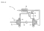
- FIG. 4 depicts a gas turbine as an embodiment of the external combustion engine according to the present invention.
- the external combustion engine 1c includes a fuel inlet 11 for introducing oxyhydrogen gas as a fuel, a compressor 12 for rotating at high speed about an output shaft 18 to compress and feed the introduced oxyhydrogen gas to the combustion chamber 13, a spark plug 14 for producing hot gas by igniting the compressed oxyhydrogen gas in the combustion chamber 13, and a turbine 17 for rotating at high speed about the output shaft 18 by virtue of hot gas ejected from the combustion chamber 13 vigorously hitting blades.
- the external combustion engine 1c also includes a regenerator 19 for increasing efficiency.
- compressed oxyhydrogen gas turns into hot water vapor gas in the combustion chamber 13, and energy of the hot gas rotates the turbine 17 at high speed.
- the compressor 12 coaxially connected to the turbine 17 via the output shaft 18 rotates at high speed, thereby continuously feeding the compressed oxyhydrogen gas to the combustion chamber 13.
- the introduced oxyhydrogen gas is finally ejected as water vapor or water.
- the external combustion engine 1c may further include a fuel injection port 15 or a water injection port 16.
- An existing fuel injected from the fuel injection port 15 or a nano-sized water mist injected from the water injection port 16 is combusted together with compressed oxyhydrogen gas, thereby achieving an effect similar to that achieved by the internal combustion engine 1a or 1b.
- the oxyhydrogen gas can be supplied from, for example, the oxyhydrogen gas-producing device 20 or the oxyhydrogen gas tank 21 shown in FIG. 3 , and the water mist can be injected into the combustion chamber 13 by using, for example, the water tank 24 and the injection device 25 shown in FIG. 3 (C) .
- the existing fuel can be injected into the combustion chamber 13 by various methods used with conventional gas turbines.
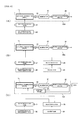
- FIG. 5 (A) is a block diagram of a power generation system using an internal combustion engine according to the present invention and its associated equipment.
- the power generation system 30a at least includes an internal combustion engine 1a (1b) and a generator 31 connected to an output shaft 7a of the internal combustion engine 1a (1b).
- the generator 31 when the output shaft 7 of the internal combustion engine 1a (1b) rotates upon supply of oxyhydrogen gas, the generator 31 produces power correspondingly.
- a power conversion device 32 may be provided on the output side of the generator 31, to convert power from the generator 31 into desired power.
- Examples of the power conversion device 32 to be used include a DC-AC inverter device that converts direct-current power DC12V outputted by the generator 31 into alternating-current power AC100V, and a device that includes inverters for stabilizing power outputted by the generator 31 and regulating the frequency of the power outputted by the generator 31 to the frequency of a commercial power supply.
- the internal combustion engine 1a (1b) may be supplied with a mixture obtained by the mixing machine 22 mixing oxyhydrogen gas and a fossil-derived fuel (existing fuel).
- the mixing machine 22 is intended to mix two types of gas at a desired ratio and can be configured by a pressure regulator, a shutoff valve, a zero governor, a-mixer, etc.
- the power generation system preferably includes control means 33 consisting of a computer and various sensors.
- the control means 33 detects an output voltage or an output current (the size of electrical load) of the generator 31 or the power conversion device 32, and changes the amount of oxyhydrogen gas or mixture to be introduced into the combustion chamber 2 and the timing of ignition, on the basis of a result of the detection. It is inefficient to always drive the internal combustion engine 1a (1b) at the maximum rotation speed, but the oxyhydrogen gas or mixture can be saved by raising/lowering the rotation speed of the internal combustion engine 1a (1b) under the aforementioned control.
- FIG. 6 (A) is a block diagram of a power generation system using an external combustion engine according to the present invention and its associated equipment.
- the power generation system 30d at least includes an external combustion engine 1c and a generator 31 connected to an output shaft 18 of the external combustion engine 1c.
- the generator 31 when the output shaft 18 of the external combustion engine 1c rotates, the generator 31 produces power correspondingly.
- the power generation system 30d may include a power conversion device 32 on the output side of the generator 31.
- the power generation system using an external combustion engine includes a power generation system 30e using an external combustion engine 1c in which a water mist is injected into a combustion chamber 13 by means of a water tank 24 and an injection device 25, and a power generation system 30f in which the amount of watermist tobe injected and the timingof ignition are controlled by control means 33.
- each of the power generation systems 30a to 30f may further include a secondary battery (not shown) provided between the generator 31 and the power conversion device 32 and rechargeable with direct-current voltage outputted by the generator 31.
- the timing of ignition is represented by an angle of rotation of the crank shaft (motion conversion mechanism 6) with respect to the piston 5 at top dead center.
- the timing of ignition is too early, combustion starts and the piston 5 is pressed down before the piston 5 reaches top dead center, i.e., before oxyhydrogen gas is appropriately compressed, resulting in a waste of resources.
- the timing of ignition is too late, oxyhydrogen gas is combusted after the piston 5 starts descent, so that a pressure change due to gas expansion cannot be fully exploited.
- the present experimentation had the timing of ignition fixed at 25° before top dead center (BTDC). Note that when compared to fossil-derived fuels such as gasoline, oxyhydrogen gas is combusted at lower speed, and conceivably, it is preferable to set the timing of ignition to an earlier point compared to the case where a fossil-derived fuel is used.
- the level was set not to fall below 5 kgf / cm 2 in order to ensure normal rotation even at low speed.
Landscapes
- Engineering & Computer Science (AREA)
- Chemical & Material Sciences (AREA)
- Combustion & Propulsion (AREA)
- General Engineering & Computer Science (AREA)
- Mechanical Engineering (AREA)
- Sustainable Energy (AREA)
- Oil, Petroleum & Natural Gas (AREA)
- Physics & Mathematics (AREA)
- Life Sciences & Earth Sciences (AREA)
- Sustainable Development (AREA)
- Thermal Sciences (AREA)
- General Chemical & Material Sciences (AREA)
- Chemical Kinetics & Catalysis (AREA)
- High Energy & Nuclear Physics (AREA)
- Output Control And Ontrol Of Special Type Engine (AREA)
- Combustion Methods Of Internal-Combustion Engines (AREA)
- Electrical Control Of Air Or Fuel Supplied To Internal-Combustion Engine (AREA)
- Electrical Control Of Ignition Timing (AREA)
- Control Of Vehicle Engines Or Engines For Specific Uses (AREA)
- Combined Controls Of Internal Combustion Engines (AREA)
Applications Claiming Priority (3)
| Application Number | Priority Date | Filing Date | Title |
|---|---|---|---|
| JP2010086090 | 2010-04-02 | ||
| JP2010285400 | 2010-12-22 | ||
| PCT/JP2011/058518 WO2011125976A1 (fr) | 2010-04-02 | 2011-04-04 | Moteur thermique et système de production d'énergie au moyen du moteur thermique |
Publications (1)
| Publication Number | Publication Date |
|---|---|
| EP2554821A1 true EP2554821A1 (fr) | 2013-02-06 |
Family
ID=44762911
Family Applications (1)
| Application Number | Title | Priority Date | Filing Date |
|---|---|---|---|
| EP11765876A Withdrawn EP2554821A1 (fr) | 2010-04-02 | 2011-04-04 | Moteur thermique et système de production d'énergie au moyen du moteur thermique |
Country Status (5)
| Country | Link |
|---|---|
| US (1) | US20130014728A1 (fr) |
| EP (1) | EP2554821A1 (fr) |
| JP (1) | JPWO2011125976A1 (fr) |
| CN (1) | CN102844544B (fr) |
| WO (1) | WO2011125976A1 (fr) |
Families Citing this family (7)
| Publication number | Priority date | Publication date | Assignee | Title |
|---|---|---|---|---|
| JP5980151B2 (ja) * | 2013-03-19 | 2016-08-31 | 三菱重工業株式会社 | ガスエンジンの排ガス制御装置 |
| BR112016006095A2 (pt) * | 2013-10-30 | 2017-08-01 | Kumar Barthakur Jitendra | motor ativado por implosão do tipo exotérmico em sistema explosivo (ieex-em) que emprega um sistema de tubulação segura (sps) e outros dispositivos de segurança |
| JP2016014384A (ja) * | 2014-07-03 | 2016-01-28 | 博信 ▲浜▼口 | エアーモーターアシスト付完全燃焼内燃機関 |
| EP3124781B1 (fr) * | 2015-07-29 | 2017-12-20 | Fuelsave GmbH | Motorisation marine et procede de fonctionnement d'un systeme de motorisation marine |
| JP6254639B2 (ja) * | 2016-05-09 | 2017-12-27 | 義夫 大河 | ジーゼルエンジンに使用される液体燃料軽減装置 |
| JPWO2018173116A1 (ja) * | 2017-03-21 | 2020-01-23 | 欣四郎 近藤 | 発電装置及びその発電方法 |
| JP7004887B2 (ja) * | 2019-12-03 | 2022-02-07 | 寛治 泉 | 水素と酸素を燃焼するエンジン。 |
Family Cites Families (31)
| Publication number | Priority date | Publication date | Assignee | Title |
|---|---|---|---|---|
| DE3146434A1 (de) * | 1981-11-24 | 1983-06-01 | Hohl, Adolf, 7180 Crailsheim | Knallgas aus zersetztem wasser |
| JPH0286923A (ja) * | 1988-09-22 | 1990-03-27 | Toyota Autom Loom Works Ltd | 水素エンジンの始動方法 |
| US5293857A (en) * | 1990-11-02 | 1994-03-15 | Stanley Meyer | Hydrogen gas fuel and management system for an internal combustion engine utilizing hydrogen gas fuel |
| JPH05256160A (ja) * | 1992-03-11 | 1993-10-05 | Mitsubishi Heavy Ind Ltd | 水素エンジンシステム |
| JPH05321764A (ja) * | 1992-05-18 | 1993-12-07 | Mazda Motor Corp | 気体燃料エンジンの燃料供給装置 |
| US6019077A (en) * | 1998-06-29 | 2000-02-01 | Gorokhovsky; Vladimir I. | Spark plug for internal combustion engine |
| JP2000028110A (ja) * | 1998-07-10 | 2000-01-25 | Kazutoshi Sakuta | 水素発生装置及び燃焼方法 |
| EP1099846B1 (fr) * | 1999-11-10 | 2005-01-12 | Wärtsilä Schweiz AG | Procédé de fonctionnement d'un moteur diesel à quatre temps |
| JP2001295705A (ja) * | 2000-04-17 | 2001-10-26 | Takeshi Hatanaka | エンジン用燃焼促進装置 |
| US20070151846A1 (en) * | 2001-04-04 | 2007-07-05 | Hydrogen Technology Applications, Inc. | Apparatus and method for the conversion of water into a clean burning combustible gas for use as an additive with other forms of fuels |
| CA2445717C (fr) | 2001-05-02 | 2010-07-13 | Japan Techno Co., Ltd. | Generateur d'hydrox et sa methode de production |
| JP2003206706A (ja) * | 2002-01-17 | 2003-07-25 | Zetto:Kk | 発電システム |
| JP2003254012A (ja) * | 2002-03-06 | 2003-09-10 | Denso Corp | 蒸気発電機 |
| CN100363600C (zh) * | 2005-06-10 | 2008-01-23 | 缪博华 | 氢气发动机 |
| AT503126B1 (de) * | 2006-06-28 | 2007-08-15 | Figl Gerhard | Verbrennungskraftmaschine |
| JP2008020167A (ja) * | 2006-07-14 | 2008-01-31 | Oyo Denki Kk | ボイラー装置およびその制御方法 |
| RO122556B1 (ro) * | 2006-07-28 | 2009-08-28 | J. Klein Dennis | Procedeu pentru utilizarea amestecurilor sărace |
| JP4586780B2 (ja) * | 2006-09-07 | 2010-11-24 | トヨタ自動車株式会社 | 作動ガス循環型エンジン |
| US8479690B2 (en) * | 2007-03-16 | 2013-07-09 | Maro Performance Group, Llc | Advanced internal combustion engine |
| JP4894733B2 (ja) * | 2007-11-16 | 2012-03-14 | マツダ株式会社 | 水素エンジンを用いたコージェネレーションシステム |
| FR2931844B1 (fr) * | 2008-06-02 | 2013-11-01 | Alex Hr Roustaei | Systemes pour la production de l'energie a la demande comme une source seule ou en assistance avec autres sources d'energie dans le domaine du transport ou de l'habitat. |
| WO2010002737A1 (fr) * | 2008-06-26 | 2010-01-07 | Cambrian Energy Development Llc | Appareil et procédé de fonctionnement d'un moteur avec une injection de fluide qui n’est pas un carburant |
| US20100038236A1 (en) * | 2008-08-18 | 2010-02-18 | Alex Rivera | Hydrogen-from-water on-demand supplemental vehicle fuel electrolyzer system |
| US8424496B2 (en) * | 2009-02-03 | 2013-04-23 | Ford Global Technologies, Llc | Methods and systems for starting a vehicle engine |
| US8109354B2 (en) * | 2009-02-13 | 2012-02-07 | Yu Chuan Technology Enterprise Co., Ltd. | Oxyhydrogen vehicle |
| US20100229839A1 (en) * | 2009-03-13 | 2010-09-16 | Fornarelli Jr Thomas | Hydrogen fuel enhancement system |
| US20100258510A1 (en) * | 2009-04-10 | 2010-10-14 | Applied Materials, Inc. | Methods and apparatus for treating effluent |
| US20100288212A1 (en) * | 2009-05-14 | 2010-11-18 | Norman Williams | On demand system for using water (HHO) as a sole fuel |
| US20100320083A1 (en) * | 2009-06-19 | 2010-12-23 | Roger Calvin Seratt | Hydrogen fuel generator |
| MY169591A (en) * | 2010-02-22 | 2019-04-22 | Univ Malaysia Pahang | Hydrogen gas fuel |
| US8714115B2 (en) * | 2010-04-09 | 2014-05-06 | Hydrogen Injection Technology, Inc. | Cylindrical hydrogen fuel generator having passive tubular cells |
-
2011
- 2011-04-04 EP EP11765876A patent/EP2554821A1/fr not_active Withdrawn
- 2011-04-04 WO PCT/JP2011/058518 patent/WO2011125976A1/fr not_active Ceased
- 2011-04-04 US US13/636,848 patent/US20130014728A1/en not_active Abandoned
- 2011-04-04 JP JP2012509652A patent/JPWO2011125976A1/ja active Pending
- 2011-04-04 CN CN201180017297.7A patent/CN102844544B/zh not_active Expired - Fee Related
Non-Patent Citations (1)
| Title |
|---|
| See references of WO2011125976A1 * |
Also Published As
| Publication number | Publication date |
|---|---|
| WO2011125976A1 (fr) | 2011-10-13 |
| US20130014728A1 (en) | 2013-01-17 |
| CN102844544A (zh) | 2012-12-26 |
| CN102844544B (zh) | 2015-04-01 |
| JPWO2011125976A1 (ja) | 2013-07-11 |
Similar Documents
| Publication | Publication Date | Title |
|---|---|---|
| EP2554821A1 (fr) | Moteur thermique et système de production d'énergie au moyen du moteur thermique | |
| Ikegami et al. | A study of hydrogen fuelled compression ignition engines | |
| CA1171672A (fr) | Allumage thermochimique d'un melange d'hydrogene et d'oxygene | |
| JP2020073794A (ja) | 内燃機関、非化石燃料式内燃機関を使用して出力を生成する方法、車両 | |
| US20140373531A1 (en) | Natural gas fueled internal combustion engine | |
| EP2690280B1 (fr) | Dispositif d'injection | |
| KR20220051100A (ko) | 암모니아를 연료로 이용하는 선박 | |
| KR20220051105A (ko) | 암모니아를 연료로 이용하는 선박 | |
| KR20220051103A (ko) | 암모니아를 연료로 이용하는 선박 | |
| KR20220051106A (ko) | 암모니아를 연료로 이용하는 선박 | |
| JP7307293B1 (ja) | 大型ターボ過給式2ストロークユニフロークロスヘッド圧縮着火内燃機関及びその動作方法 | |
| CN114856842B (zh) | 一种基于hho的内燃机燃烧控制系统及方法 | |
| AU2014290486B2 (en) | Ignition system for low grade synthesis gas | |
| CN112789403B (zh) | 废气再循环系统及包括该废气再循环系统的船舶 | |
| JP2892235B2 (ja) | コジェネレーション型ガスエンジン | |
| EP4158167A1 (fr) | Échange gazeux dans des moteurs à combustion interne pour une efficacité accrue | |
| Bakar et al. | The internal combustion engine diversification technology and fuel research for the future: A Review | |
| CN203627017U (zh) | 燃油气内燃机 | |
| KR20120064214A (ko) | 수소-산소 혼합기를 이용한 고효율 청정 엔진 | |
| CN204060985U (zh) | 一种内燃机原子增压节能装置 | |
| KR20120059162A (ko) | 엔진 유닛 및 엔진 유닛의 구동방법 | |
| KR102839233B1 (ko) | 배기열을 회수하는 로터리 방식의 회전식 앳킨스 싸이클 엔진 | |
| Yelvington et al. | Oxygen-enriched combustion for industrial diesel engines | |
| Sureshkumar et al. | Experimental Analysis of Hydrogen-Diesel Combination with Timed Manifold Injection | |
| CN103967652A (zh) | 活塞冲压自燃脉冲喷气发动机 |
Legal Events
| Date | Code | Title | Description |
|---|---|---|---|
| PUAI | Public reference made under article 153(3) epc to a published international application that has entered the european phase |
Free format text: ORIGINAL CODE: 0009012 |
|
| 17P | Request for examination filed |
Effective date: 20121022 |
|
| AK | Designated contracting states |
Kind code of ref document: A1 Designated state(s): AL AT BE BG CH CY CZ DE DK EE ES FI FR GB GR HR HU IE IS IT LI LT LU LV MC MK MT NL NO PL PT RO RS SE SI SK SM TR |
|
| DAX | Request for extension of the european patent (deleted) | ||
| STAA | Information on the status of an ep patent application or granted ep patent |
Free format text: STATUS: THE APPLICATION HAS BEEN WITHDRAWN |
|
| 18W | Application withdrawn |
Effective date: 20160223 |