EP2554849A2 - Compresseur - Google Patents
Compresseur Download PDFInfo
- Publication number
- EP2554849A2 EP2554849A2 EP12178443A EP12178443A EP2554849A2 EP 2554849 A2 EP2554849 A2 EP 2554849A2 EP 12178443 A EP12178443 A EP 12178443A EP 12178443 A EP12178443 A EP 12178443A EP 2554849 A2 EP2554849 A2 EP 2554849A2
- Authority
- EP
- European Patent Office
- Prior art keywords
- chamber
- oil reservoir
- reservoir chamber
- oil
- auxiliary
- Prior art date
- Legal status (The legal status is an assumption and is not a legal conclusion. Google has not performed a legal analysis and makes no representation as to the accuracy of the status listed.)
- Withdrawn
Links
Images
Classifications
-
- F—MECHANICAL ENGINEERING; LIGHTING; HEATING; WEAPONS; BLASTING
- F04—POSITIVE - DISPLACEMENT MACHINES FOR LIQUIDS; PUMPS FOR LIQUIDS OR ELASTIC FLUIDS
- F04C—ROTARY-PISTON, OR OSCILLATING-PISTON, POSITIVE-DISPLACEMENT MACHINES FOR LIQUIDS; ROTARY-PISTON, OR OSCILLATING-PISTON, POSITIVE-DISPLACEMENT PUMPS
- F04C18/00—Rotary-piston pumps specially adapted for elastic fluids
- F04C18/02—Rotary-piston pumps specially adapted for elastic fluids of arcuate-engagement type, i.e. with circular translatory movement of co-operating members, each member having the same number of teeth or tooth-equivalents
-
- F—MECHANICAL ENGINEERING; LIGHTING; HEATING; WEAPONS; BLASTING
- F04—POSITIVE - DISPLACEMENT MACHINES FOR LIQUIDS; PUMPS FOR LIQUIDS OR ELASTIC FLUIDS
- F04C—ROTARY-PISTON, OR OSCILLATING-PISTON, POSITIVE-DISPLACEMENT MACHINES FOR LIQUIDS; ROTARY-PISTON, OR OSCILLATING-PISTON, POSITIVE-DISPLACEMENT PUMPS
- F04C29/00—Component parts, details or accessories of pumps or pumping installations, not provided for in groups F04C18/00 - F04C28/00
- F04C29/02—Lubrication; Lubricant separation
- F04C29/028—Means for improving or restricting lubricant flow
-
- F—MECHANICAL ENGINEERING; LIGHTING; HEATING; WEAPONS; BLASTING
- F04—POSITIVE - DISPLACEMENT MACHINES FOR LIQUIDS; PUMPS FOR LIQUIDS OR ELASTIC FLUIDS
- F04C—ROTARY-PISTON, OR OSCILLATING-PISTON, POSITIVE-DISPLACEMENT MACHINES FOR LIQUIDS; ROTARY-PISTON, OR OSCILLATING-PISTON, POSITIVE-DISPLACEMENT PUMPS
- F04C29/00—Component parts, details or accessories of pumps or pumping installations, not provided for in groups F04C18/00 - F04C28/00
- F04C29/02—Lubrication; Lubricant separation
-
- F—MECHANICAL ENGINEERING; LIGHTING; HEATING; WEAPONS; BLASTING
- F04—POSITIVE - DISPLACEMENT MACHINES FOR LIQUIDS; PUMPS FOR LIQUIDS OR ELASTIC FLUIDS
- F04C—ROTARY-PISTON, OR OSCILLATING-PISTON, POSITIVE-DISPLACEMENT MACHINES FOR LIQUIDS; ROTARY-PISTON, OR OSCILLATING-PISTON, POSITIVE-DISPLACEMENT PUMPS
- F04C18/00—Rotary-piston pumps specially adapted for elastic fluids
- F04C18/02—Rotary-piston pumps specially adapted for elastic fluids of arcuate-engagement type, i.e. with circular translatory movement of co-operating members, each member having the same number of teeth or tooth-equivalents
- F04C18/0207—Rotary-piston pumps specially adapted for elastic fluids of arcuate-engagement type, i.e. with circular translatory movement of co-operating members, each member having the same number of teeth or tooth-equivalents both members having co-operating elements in spiral form
- F04C18/0215—Rotary-piston pumps specially adapted for elastic fluids of arcuate-engagement type, i.e. with circular translatory movement of co-operating members, each member having the same number of teeth or tooth-equivalents both members having co-operating elements in spiral form where only one member is moving
-
- F—MECHANICAL ENGINEERING; LIGHTING; HEATING; WEAPONS; BLASTING
- F04—POSITIVE - DISPLACEMENT MACHINES FOR LIQUIDS; PUMPS FOR LIQUIDS OR ELASTIC FLUIDS
- F04C—ROTARY-PISTON, OR OSCILLATING-PISTON, POSITIVE-DISPLACEMENT MACHINES FOR LIQUIDS; ROTARY-PISTON, OR OSCILLATING-PISTON, POSITIVE-DISPLACEMENT PUMPS
- F04C18/00—Rotary-piston pumps specially adapted for elastic fluids
- F04C18/30—Rotary-piston pumps specially adapted for elastic fluids having the characteristics covered by two or more of groups F04C18/02, F04C18/08, F04C18/22, F04C18/24, F04C18/48, or having the characteristics covered by one of these groups together with some other type of movement between co-operating members
- F04C18/34—Rotary-piston pumps specially adapted for elastic fluids having the characteristics covered by two or more of groups F04C18/02, F04C18/08, F04C18/22, F04C18/24, F04C18/48, or having the characteristics covered by one of these groups together with some other type of movement between co-operating members having the movement defined in group F04C18/08 or F04C18/22 and relative reciprocation between the co-operating members
- F04C18/344—Rotary-piston pumps specially adapted for elastic fluids having the characteristics covered by two or more of groups F04C18/02, F04C18/08, F04C18/22, F04C18/24, F04C18/48, or having the characteristics covered by one of these groups together with some other type of movement between co-operating members having the movement defined in group F04C18/08 or F04C18/22 and relative reciprocation between the co-operating members with vanes reciprocating with respect to the inner member
-
- F—MECHANICAL ENGINEERING; LIGHTING; HEATING; WEAPONS; BLASTING
- F04—POSITIVE - DISPLACEMENT MACHINES FOR LIQUIDS; PUMPS FOR LIQUIDS OR ELASTIC FLUIDS
- F04C—ROTARY-PISTON, OR OSCILLATING-PISTON, POSITIVE-DISPLACEMENT MACHINES FOR LIQUIDS; ROTARY-PISTON, OR OSCILLATING-PISTON, POSITIVE-DISPLACEMENT PUMPS
- F04C2240/00—Components
- F04C2240/80—Other components
- F04C2240/809—Lubricant sump
-
- F—MECHANICAL ENGINEERING; LIGHTING; HEATING; WEAPONS; BLASTING
- F04—POSITIVE - DISPLACEMENT MACHINES FOR LIQUIDS; PUMPS FOR LIQUIDS OR ELASTIC FLUIDS
- F04C—ROTARY-PISTON, OR OSCILLATING-PISTON, POSITIVE-DISPLACEMENT MACHINES FOR LIQUIDS; ROTARY-PISTON, OR OSCILLATING-PISTON, POSITIVE-DISPLACEMENT PUMPS
- F04C29/00—Component parts, details or accessories of pumps or pumping installations, not provided for in groups F04C18/00 - F04C28/00
- F04C29/02—Lubrication; Lubricant separation
- F04C29/026—Lubricant separation
Definitions
- the present invention relates to a compressor including a compressing portion, which is provided in a housing and compresses refrigerant, an oil separation chamber, which receives refrigerant from the compressing portion and has a peripheral wall for causing the refrigerant to swirl to separate lubricant oil mixed in the refrigerant, and an oil reservoir chamber for storing the lubricant oil separated from the refrigerant.
- the present invention relates to a compressor that is structured to supply lubricant oil in the oil reservoir chamber to the refrigerant suction-side structure of the compressing portion.
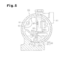
- FIG. 5 shows a compressor 80 disclosed in Japanese Laid-Open Patent Publication No. 2005-171860 .
- the compressor 80 includes a housing 81, a refrigerant discharge chamber 82 communicating with a compressing portion (not shown), a refrigerant outlet 83 communicating with the refrigerant discharge chamber 82, and an oil separation chamber 84.
- the compressor 80 accommodates in the housing 81 the oil separation chamber 84 formed in a refrigerant passage between the refrigerant discharge chamber 82 and the refrigerant outlet 83.
- the oil separation chamber 84 is defined by a cylindrical inner wall 85.
- a cylindrical separation pipe 86 is arranged in the oil separation chamber 84.
- the separation pipe 86 has an upper end connected to the refrigerant outlet 83 and a lower end that is open at a position separated from a bottom wall 84b of the oil separation chamber 84.
- a pair of communication holes 87 is formed in an upper part of the oil separation chamber 84 that is closer to the refrigerant discharge chamber 82.
- An introducing hole 84a is formed at a center of the bottom wall 84b of the oil separation chamber 84.
- An oil reservoir chamber 88 is formed below the oil separation chamber 84.
- the oil reservoir chamber 88 is divided into a first oil reservoir chamber 90 and a second oil reservoir chamber 91 by a partition 89.
- the first and second oil reservoir chambers 90, 91 have at the lower portions cutouts 90a, 91a, respectively.
- the cutouts 90a, 91a are connected to each other by a communication passage 92.
- the first oil reservoir chamber 90 is connected to the oil separation chamber 84 by the introducing hole 84a.
- the second oil reservoir chamber 91 is connected to the refrigerant suction-side structure of the compressing portion.
- refrigerant After being delivered to the oil separation chamber 84 from the refrigerant discharge chamber 82 via the communication holes 87, refrigerant swirls along the inner wall 85 of the oil separation chamber 84. At that time, the refrigerant is discharged from the refrigerant outlet 83 to the outside of the compressor 80 via the lower end of the separation pipe 86. On the other hand, lubricant oil in the refrigerant collects on the inner wall 85 to be separated from the refrigerant. The separated lubricant oil is introduced to the first oil reservoir chamber 90 via the introducing hole 84a of the oil separation chamber 84.
- the lubricant oil moves to the second oil reservoir chamber 91 via the cutouts 90a, 91a and the communication passage 92 and is then supplied to the refrigerant suction-side structure of the compressing portion.
- the compressor 80 even if the momentum of lubricant oil from the oil separation chamber 84 disturbs the surface of the oil in the first oil reservoir chamber 90, the oil surface in the second oil reservoir chamber 91 is not disturbed. This prevents refrigerant in gaseous state from being supplied to the refrigerant suction-side structure. Therefore, the compressor 80 is capable of steadily supplying lubricant oil to the refrigerant suction-side structure.
- lubricant oil mixed in refrigerant is separated from the refrigerant by collecting on the inner wall 85 of the oil separation chamber 84.
- the separated lubricant oil flows from the inner wall 85 and along the bottom wall 84b of the oil separation chamber 84 and introduced to the oil reservoir chamber 88 via the introducing hole 84a of the bottom wall 84b. Since the lubricant oil in the oil separation chamber 84 flows along the bottom wall 84b, it takes time for the lubricant oil to be introduced to the oil reservoir chamber 88. While flowing along the bottom wall 84b, the lubricant oil might be carried away to the outside of the compressor 80 together with refrigerant.
- a compressor that includes a compressing portion, an oil separation chamber, an auxiliary oil reservoir chamber, and a main oil reservoir chamber.
- the compressing portion is located in a housing to compress refrigerant.
- refrigerant is introduced from the compressing portion.
- the oil separation chamber has a peripheral wall for causing refrigerant to swirl to separate lubricant oil mixed in the refrigerant.
- the auxiliary oil reservoir chamber and the main oil reservoir chamber retain lubricant oil that is separated from refrigerant.
- a part of the auxiliary oil reservoir chamber is defined by the peripheral wall of the oil separation chamber.
- An introducing passage for introducing lubricant oil in the oil separation chamber to the auxiliary oil reservoir chamber is formed in the peripheral wall.
- the introducing passage has an inlet located at one end and an outlet located at the other end.
- the inlet of the introducing passage opens to the oil separation chamber on an inner surface of the peripheral wall.
- the outlet of the introducing passage opens to the auxiliary oil reservoir chamber.
- the main oil reservoir chamber is located below the auxiliary oil reservoir chamber in the direction of gravity.
- a drain port is formed in a bottom wall of the auxiliary oil reservoir chamber. The drain port drains lubricant oil in the auxiliary oil reservoir chamber to the main oil reservoir chamber, and lubricant oil in the main oil reservoir chamber is supplied to a suction-side structure of the compressing portion.
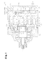
- a scroll compressor 10 according to one embodiment of the present invention will now be described with reference to Figs. 1 to 4 .
- the housing of the scroll compressor 10 is formed by coupling a front housing member 11 to one end of a center housing member (shell) 12 and coupling a rear housing member 13 to the other end of the center housing member 12.
- the front housing member 11, the center housing member 12, and the rear housing member 13 are fastened together using fastener bolts B.
- the center housing member 12, the front housing member 11, and the rear housing member 13 function as housing forming members.
- the housing of the scroll compressor 10 accommodates in it a scroll-type compressing portion C for compressing refrigerant.
- the center housing member 12 is formed as a cylinder that has a closed end and an opening facing the front housing member 11.
- the fixed scroll 16, which is part of the compressing portion C, is formed in the center housing member 12.
- the fixed scroll 16 is formed by a fixed base plate 14, which forms a closed end of the center housing member 12, and a fixed volute wall 15, which extends from the fixed base plate 14 and within the center housing member 12.
- the front housing member 11 rotationally supports a large diameter portion 17a of a rotary shaft 17 with a radial bearing 18.
- the large diameter portion 17a of the rotary shaft 17 has an eccentric shaft 19, which is integrally formed with an end face 17b facing the fixed scroll 16.
- the axis of the eccentric shaft 19 is offset from the axis of the rotary shaft 17.
- the eccentric shaft 19 supports a balance weight 20 and a bushing 21 such that the balance weight 20 and the bushing 21 are rotational relative to the eccentric shaft 19.
- the bushing 21 supports a orbiting scroll 23, which forms part of the compressing portion C, by means of a needle bearing 24 such that the orbiting scroll 23 faces the fixed scroll 16.
- the orbiting scroll 23 is rotational relative to the bushing 21.
- the orbiting scroll 23 is formed by an orbiting base plate 25, which faces the fixed base plate 14, and an orbiting volute wall 26, which extends from the orbiting base plate 25 to mesh with the fixed volute wall 15.
- a compression chamber S having a variable volume is defined between the fixed base plate 14 of the fixed scroll 16 and the orbiting base plate 25 of the orbiting scroll 23.
- a discharge port 14a which communicates with the compression chamber S, is formed in the fixed base plate 14.
- the discharge port 14a is selectively opened and closed by a discharge valve flap 14b, which is fixed to the fixed base plate 14.
- a retainer 14c fixed to the fixed base plate 14 limits the opening degree of the discharge valve flap 14b.
- the discharge port 14a communicates with a discharge chamber 31, which is defined by the center housing member 12 and the rear housing member 13.
- a suction chamber 30, which is the suction-side structure of the compressing portion C, is defined between the peripheral wall of the center housing member 12 and the outermost part of the orbiting volute wall 26 of the orbiting scroll 23. That is, in the housing, the suction chamber 30 is located in a radially outer portion of the compressing portion C.
- a suction port 12a which communicates with the suction chamber 30, is formed in the peripheral wall of the center housing member 12.
- the front housing member 11 has anti-rotation holes 11a, which are formed in an end face that faces the radially outer portion of the orbiting base plate 25.
- the anti-rotation holes 11a are arranged in the circumferential direction of the orbiting base plate 25.
- the orbiting base plate 25 has anti-rotation holes 25a, the number of which is equal to the number of the anti-rotation holes 11 a.
- the anti-rotation holes 25a are arranged in the circumferential direction of the orbiting base plate 25. Ends of anti-rotation pins 32 are inserted in the anti-rotation holes 11a, 25a.
- the orbiting scroll 23 orbit, so that refrigerant is drawn into the suction chamber 30 via the suction port 12a and then flows to the space between the fixed base plate 14 and the orbiting base plate 25.
- the circumferential surface of each anti-rotation pin 32 slides along the inner circumferential surface of the corresponding anti-rotation hole 11a, 25a. This allows the orbiting scroll 23 to orbit without rotating.
- the compression chamber S moves toward the inner ends of the volute walls 15, 26 of the scrolls 16, 23, while reducing its volume. Refrigerant gas that has been compressed by the reduction in the volume of the compression chamber S is discharged to the discharge chamber 31 via the discharge port 14a.
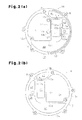
- a muffler chamber 40 an oil separation chamber 41, an auxiliary oil reservoir chamber 42, and a main oil reservoir chamber 44, which are defined by coupling the center housing member 12 and the rear housing member 13 together, will now be described.
- a first annular wall 12c extends from a peripheral edge of the fixed base plate 14 of the center housing member 12 at a position facing the rear housing member 13.
- a second annular wall 13c extends from a peripheral edge of a bottom 13a of the rear housing member 13 at a position facing the first annular wall 12c.
- a first dividing wall 12d is formed in a lower portion with respect to the direction of gravity on the fixed base plate 14.
- the first dividing wall 12d connects two points of the first annular wall 12c.
- a space surrounded by the fixed base plate 14, the first dividing wall 12d, and the first annular wall 12c forms a part of the main oil reservoir chamber 44.
- a first dividing wall 13d is formed in a lower portion with respect to the direction of gravity on the bottom 13a of the rear housing member 13.
- the first dividing wall 13d connects two points of the second annular wall 13c.
- a space surrounded by the bottom 13a, the first dividing wall 13d, and the second annular wall 13c forms a part of the main oil reservoir chamber 44.
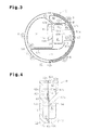
- FIG. 4 when the center housing member 12 and the rear housing member 13 are coupled together, the two parts of the main oil reservoir chamber 44 are joined, so that the main oil reservoir chamber 44 is formed in the housing.
- an introducing passage 12h is formed in the end face of the first annular wall 12c of the center housing member 12. The introducing passage 12h extends substantially halfway around the first annular wall 12c to connect the main oil reservoir chamber 44 and the suction chamber 30 to each other.
- a second dividing wall 12e is formed in an upper portion with respect to the direction of gravity on the fixed base plate 14.
- the second dividing wall 12e connects two points of the first annular wall 12c.
- a space surrounded by the fixed base plate 14, the second dividing wall 12e, and the first annular wall 12c forms a part of the muffler chamber 40.
- a second dividing wall 13e is formed in an upper portion with respect to the direction of gravity on the bottom 13a of the rear housing member 13. The second dividing wall 13e connects two points of the second annular wall 13c.
- a space surrounded by the bottom 13a, the second dividing wall 13e, and the second annular wall 13c forms a part of the muffler chamber 40.
- the two parts of the muffler chamber 40 are joined, so that the muffler chamber 40 is formed in the housing.
- the muffler chamber 40 communicates with an outlet hole 13b formed in the second annular wall 13c, and the outlet hole 13b is connected to the outside.
- a third dividing wall 12f is formed on the fixed base plate 14 to extend in the direction of gravity and connect the first dividing wall 12d and the second dividing wall 12e to each other.
- a space surrounded by the fixed base plate 14, the first annular wall 12c, the first dividing wall 12d, the second dividing wall 12e, and the third dividing wall 12f forms a part of the discharge chamber 31.
- a third dividing wall 13f is formed on the bottom 13a of the rear housing member 13 to extend in the direction of gravity and connect the first dividing wall 13d and the second dividing wall 13e to each other.
- a space surrounded by the bottom 13a, the second annular wall 13c, the first dividing wall 13d, the second dividing wall 13e, and the third dividing wall 13f forms a part of the discharge chamber 31.
- the center housing member 12 and the rear housing member 13 are coupled together, the two parts of the discharge chamber 31 are joined, so that the discharge chamber 31 is formed in the housing.
- a fourth dividing wall 12g is formed on the fixed base plate 14 at a position beside the third dividing wall 12f to connect the first dividing wall 12d and the second dividing wall 12e to each other.
- a space surrounded by the fixed base plate 14, the first dividing wall 12d, the second dividing wall 12e, the third dividing wall 12f, and the fourth dividing wall 12g forms a part of the oil separation chamber 41.
- a fourth dividing wall 13g is formed on the bottom 13a of the rear housing member 13 at a position beside the third dividing wall 13f to connect the first dividing wall 13d and the second dividing wall 13e to each other.
- a space surrounded by the bottom 13a, the first dividing wall 13d, the second dividing wall 13e, the third dividing wall 13f, and the fourth dividing wall 13g forms a part of the oil separation chamber 41.
- the center housing member 12 and the rear housing member 13 are coupled together, the two parts of the oil separation chamber 41 are joined, so that the oil separation chamber 41 is formed in the housing.
- a space surrounded by the fixed base plate 14, the first annular wall 12c, the first dividing wall 12d, and the fourth dividing wall 12g forms a part of the auxiliary oil reservoir chamber 42.
- the volume of the auxiliary oil reservoir chamber 42 is less than the volume of the main oil reservoir chamber 44.
- a space surrounded by the bottom 13a, the second annular wall 13c, the first dividing wall 13d, and the fourth dividing wall 13g forms a part of the auxiliary oil reservoir chamber 42.
- the center housing member 12 and the rear housing member 13 are coupled together, the two parts of the auxiliary oil reservoir chamber 42 are joined, so that the auxiliary oil reservoir chamber 42 is formed in the housing.
- the oil separation chamber 41 is arranged beside the discharge chamber 31. That is, the oil separation chamber 41 is located at position spaced from the discharge chamber 31 in a direction perpendicular to the direction of gravity (the vertical direction).
- the peripheral wall of the oil separation chamber 41 is shaped like a cylinder by combining the fixed base plate 14 of the center housing member 12, the third dividing wall 12f, the fourth dividing wall 12g, the bottom 13a of the rear housing member 13, the third dividing wall 13f, and the fourth dividing wall 13g.
- the peripheral wall of the oil separation chamber 41 refers to a combination of the walls defining the oil separation chamber 41 except for the upper wall (the second dividing walls 12e, 13e) and the bottom wall (the first dividing walls 12d, 13d).
- the peripheral wall is formed to have a cylindrical shape to generate a swirling flow of refrigerant in the oil separation chamber 41.
- a discharge hole 31 a is formed in the third dividing wall 12f, which forms a part of the peripheral wall of the oil separation chamber 41.
- the discharge hole 31 a connects the discharge chamber 31 and the oil separation chamber 41 to each other.
- a discharge passage 41 a is formed in center portions of the second dividing walls 12e, 13e, which forms the upper wall of the oil separation chamber 41.
- the discharge passage 41 a connects the oil separation chamber 41 and the muffler chamber 40 to each other.
- the discharge chamber 31 and the muffler chamber 40 are connected to each other via the oil separation chamber 41, so that refrigerant delivered to the discharge chamber 31 is then discharged to the muffler chamber 40 via the oil separation chamber 41.
- the auxiliary oil reservoir chamber 42 is arranged beside the oil separation chamber 41, that is, at position spaced from the oil separation chamber 41 in a direction perpendicular to the direction of gravity (the vertical direction), and also above the bottom of the oil separation chamber 41.
- the auxiliary oil reservoir chamber 42 is defined by combining the fixed base plate 14 of the center housing member 12, the first annular wall 12c, the first dividing wall 12d, the fourth dividing wall 12g, the second dividing wall 12e, the bottom 13a of the rear housing member 13, the second annular wall 13c, the first dividing wall 13d, the fourth dividing wall 13g, and the second dividing wall 13e.
- the fourth dividing walls 12g, 13g which form the auxiliary oil reservoir chamber 42, also form the peripheral wall of the oil separation chamber 41.
- a part of the auxiliary oil reservoir chamber 42 is defined by the peripheral wall of the oil separation chamber 41. That is, the fourth dividing wall 12g, 13g function to form both of the oil separation chamber 41 and the auxiliary oil reservoir chamber 42.
- the oil separation chamber 41 and the auxiliary oil reservoir chamber 42 are adjacent to each other (arranged side-by-side) in a direction perpendicular to the direction of gravity with the fourth dividing walls 12g, 13g in between.
- An introducing passage 43 is formed in the fourth dividing wall 12g of the center housing member 12 by making a recess on the end face of the fourth dividing wall 12g.
- the introducing passage 43 connects the oil separation chamber 41 and the auxiliary oil reservoir chamber 42 to each other.
- An opening of the introducing passage 43 that extends in the direction of the passage is closed by the gasket 50 when the gasket 50 is held between the fourth dividing walls 12g, 13g.
- the introducing passage 43 has an inlet 43a at one end and an outlet 43b at the other end.
- the inlet 43a communicates with a lower portion of the oil separation chamber 41 in the direction of gravity.
- the outlet 43b communicates with a lower portion of the auxiliary oil reservoir chamber 42 at a position higher than the inlet 43a.
- the inlet 43a opens to the oil separation chamber 41 on the fourth dividing wall 12g (the inner surface of the peripheral wall).
- the outlet 43b opens to the auxiliary oil reservoir chamber 42 on the fourth dividing wall 12g.
- lubricant oil that has been separated in the oil separation chamber 41 is introduced to the lower portion of the auxiliary oil reservoir chamber 42 via the introducing passage 43.
- the cross-sectional area of the introducing passage 43 is smaller than the cross-sectional area of the oil separation chamber 41, which is perpendicular to the direction of gravity.
- the main oil reservoir chamber 44 is located below the discharge chamber 31, the oil separation chamber 41, and the auxiliary oil reservoir chamber 42 in the direction of gravity.
- the first dividing wall 12d of the center housing member 12 and the first dividing wall 13d of the rear housing member 13 form the bottom wall of the auxiliary oil reservoir chamber 42 and the upper wall of the main oil reservoir chamber 44.
- a drain port 45 is formed in a part of the first dividing wall 13d of the rear housing member 13 that forms the bottom wall of the auxiliary oil reservoir chamber 42.
- the drain port 45 is formed by making a recess in the end face of the first dividing wall 13d and connects the auxiliary oil reservoir chamber 42 and the main oil reservoir chamber 44 to each other. An opening of the drain port 45 that extends in the direction of the passage is closed by the gasket 50 when the gasket 50 is held between the first dividing walls 12d, 13d.
- the cross-sectional area of the drain port 45 is smaller than the cross-sectional area of the auxiliary oil reservoir chamber 42 and the main oil reservoir chamber 44, which is perpendicular to the direction of gravity.
- the introducing passage 43 and the drain port 45 which communicate with the auxiliary oil reservoir chamber 42, are on the other sides of the gasket 50, namely, on the side corresponding to the center housing member 12 and the side corresponding to the rear housing member 13, respectively.
- the auxiliary oil reservoir chamber 42 is divided into an introduction chamber 42a corresponding to the outlet 43b and a drain chamber 42b corresponding to the drain port 45 by a dividing portion 50a, which is formed by the gasket 50.
- a hole is formed in the gasket 50 to open the entire auxiliary oil reservoir chamber 42.
- the dividing portion 50a is formed by reducing the size of that hole so that only an upper portion of the auxiliary oil reservoir chamber 42 is open.
- the dividing portion 50a has a height that is approximately half the height of the auxiliary oil reservoir chamber 42 in the direction of gravity.
- a communication portion 42c for connecting the introduction chamber 42a and the drain chamber 42b to each other is formed between the upper edge of the dividing portion 50a and the upper wall of the auxiliary oil reservoir chamber 42.
- Refrigerant that has been compressed by the compressing portion C is discharged to an upper portion of the oil separation chamber 41 from the discharge chamber 31 via the discharge hole 31 a, and then swirls from the upper portion toward the lower portion along the peripheral wall of the oil separation chamber 41.
- the swirling causes lubricant oil contained in the refrigerant to collect on the peripheral wall of the oil separation chamber 41 to be separated from the refrigerant.
- the refrigerant, from which lubricant oil has been removed in the oil separation chamber 41 is delivered to the muffler chamber 40 via the discharge passage 41 a, and discharged to the outside of the scroll compressor 10 via the outlet hole 13b.
- Lubricant oil collected on the peripheral wall of the oil separation chamber 41 reaches the inlet 43a of the introducing passage 43 opening in the inner surface of the peripheral wall, and is then drawn to the lower portion of the auxiliary oil reservoir chamber 42 via the introducing passage 43 due to the pressure difference between the oil separation chamber 41 and the auxiliary oil reservoir chamber 42.
- the cross-sectional area of the introducing passage 43 is smaller than the cross-sectional area of the oil separation chamber 41, the flow of the lubricant oil is throttled by the introducing passage 43 when passing therethrough, and the pressure is reduced.
- lubricant oil is then introduced to the introduction chamber 42a from the outlet 43b. Since the position of the outlet 43b is lower than the upper end of the dividing portion 50a, lubricant oil is blocked by the dividing portion 50a to be temporarily retained in the introduction chamber 42a. Thereafter, when the lubricant oil retained in the introduction chamber 42a overflows, the lubricant oil flows to the drain chamber 42b via the communication portion 42c.
- lubricant oil flows to the main oil reservoir chamber 44 via the drain port 45 under its own weight.
- the cross-sectional area of the drain port 45 is smaller than the cross-sectional area of the auxiliary oil reservoir chamber 42 and the main oil reservoir chamber 44. The flow of the lubricant oil is therefore throttled by the drain port 45 when passing therethrough, and the pressure is reduced.
- the lubricant oil that has been separated in the oil separation chamber 41 is delivered to the main oil reservoir chamber 44 while its flow velocity (or momentum) is reduced by passing through the introducing passage 43, the auxiliary oil reservoir chamber 42, and the drain port 45. Thereafter, the lubricant oil in the main oil reservoir chamber 44 is supplied to the suction chamber 30 via the introducing passage 12h.
- the above embodiment has the following advantage.
- the oil separation chamber 41, the auxiliary oil reservoir chamber 42, and the main oil reservoir chamber 44 are each formed across the center housing member 12 and the rear housing member 13.
- each of the chambers 41, 42, 44 may be formed in one of the rear housing member 13 and the center housing member 12.
- the dividing portion 50a is formed by the gasket 50.
- the dividing portion 50a does not necessarily need to be formed by the gasket 50. Instead, a dividing portion may be directly formed on the center housing member 12 or the rear housing member 13. Alternatively, a member different from the gasket 50 may be used to form a dividing portion.
- the auxiliary oil reservoir chamber 42 is divided into the introduction chamber 42a and the drain chamber 42b.
- the auxiliary oil reservoir chamber 42 does not necessarily need to be divided.
- the introducing passage 43 is formed such that the inlet 43a is located in a lower portion of the oil separation chamber 41, and the outlet 43b is located above the inlet 43a and in a lower portion of the auxiliary oil reservoir chamber 42.
- the structure of the introducing passage 43 may be changed. For example, as long as the inlet 43a is formed in the peripheral wall of the oil separation chamber 41, the position of the inlet 43a may be changed as needed.
- the inlet 43a may be formed in an upper portion of the oil separation chamber 41.
- the compressing portion C is a scroll type compressing portion.
- the compressing portion C may be a vane type compressing portion.
Landscapes
- Engineering & Computer Science (AREA)
- Mechanical Engineering (AREA)
- General Engineering & Computer Science (AREA)
- Applications Or Details Of Rotary Compressors (AREA)
- Compressor (AREA)
- Rotary Pumps (AREA)
Applications Claiming Priority (1)
| Application Number | Priority Date | Filing Date | Title |
|---|---|---|---|
| JP2011170342A JP5601288B2 (ja) | 2011-08-03 | 2011-08-03 | 圧縮機 |
Publications (2)
| Publication Number | Publication Date |
|---|---|
| EP2554849A2 true EP2554849A2 (fr) | 2013-02-06 |
| EP2554849A3 EP2554849A3 (fr) | 2017-03-08 |
Family
ID=46639344
Family Applications (1)
| Application Number | Title | Priority Date | Filing Date |
|---|---|---|---|
| EP12178443.3A Withdrawn EP2554849A3 (fr) | 2011-08-03 | 2012-07-30 | Compresseur |
Country Status (6)
| Country | Link |
|---|---|
| US (1) | US8882482B2 (fr) |
| EP (1) | EP2554849A3 (fr) |
| JP (1) | JP5601288B2 (fr) |
| KR (1) | KR101295614B1 (fr) |
| CN (1) | CN102913451B (fr) |
| BR (1) | BR102012019211A2 (fr) |
Cited By (2)
| Publication number | Priority date | Publication date | Assignee | Title |
|---|---|---|---|---|
| FR3031549A1 (fr) * | 2015-01-13 | 2016-07-15 | Danfoss Commercial Compressors | |
| EP4105485A4 (fr) * | 2020-09-30 | 2023-05-31 | Anhui Welling Auto Parts Co., Ltd. | Compresseur à spirale, dispositif de réfrigération et véhicule |
Families Citing this family (9)
| Publication number | Priority date | Publication date | Assignee | Title |
|---|---|---|---|---|
| JP5510485B2 (ja) * | 2012-03-23 | 2014-06-04 | 株式会社豊田自動織機 | 圧縮機 |
| JP6181405B2 (ja) * | 2013-04-08 | 2017-08-16 | サンデンホールディングス株式会社 | 圧縮機 |
| KR102229832B1 (ko) * | 2015-10-07 | 2021-03-22 | 한온시스템 주식회사 | 전동압축기용 유분리기 |
| DE102018124301A1 (de) * | 2017-11-01 | 2019-05-02 | Hanon Systems | Scrollverdichter |
| KR102087135B1 (ko) * | 2018-08-16 | 2020-03-10 | 에스트라오토모티브시스템 주식회사 | 오일 회수 수단이 구비된 스크롤 압축기 |
| KR102809392B1 (ko) * | 2019-11-13 | 2025-05-19 | 현대모비스 주식회사 | 전동식 컴프레서 장치 |
| KR102522649B1 (ko) * | 2020-03-30 | 2023-04-18 | 두원중공업(주) | 스크롤 압축기 |
| CN114320895B (zh) * | 2020-09-30 | 2025-12-12 | 安徽威灵汽车部件有限公司 | 涡旋压缩机、制冷设备及车辆 |
| JP7833564B2 (ja) * | 2022-10-12 | 2026-03-19 | ハンオン システムズ | スクロール圧縮機 |
Citations (1)
| Publication number | Priority date | Publication date | Assignee | Title |
|---|---|---|---|---|
| JP2005171860A (ja) | 2003-12-10 | 2005-06-30 | Sanden Corp | 圧縮機 |
Family Cites Families (18)
| Publication number | Priority date | Publication date | Assignee | Title |
|---|---|---|---|---|
| DE2922307A1 (de) * | 1978-06-02 | 1979-12-06 | Hitachi Ltd | Taumelscheiben-verdichter |
| JP3120537B2 (ja) * | 1992-02-28 | 2000-12-25 | 株式会社豊田自動織機製作所 | 往復動型圧縮機 |
| JP3120697B2 (ja) | 1995-05-25 | 2000-12-25 | 株式会社豊田自動織機製作所 | 斜板式圧縮機 |
| JP4000634B2 (ja) * | 1997-09-05 | 2007-10-31 | 株式会社デンソー | スクロール型圧縮機 |
| DE69823117T2 (de) | 1997-08-29 | 2005-04-28 | Kabushiki Kaisha Toyota Jidoshokki, Kariya | Spiralverdichter |
| JP3721933B2 (ja) * | 2000-04-17 | 2005-11-30 | 株式会社デンソー | 圧縮機 |
| DE10213252B4 (de) | 2001-03-26 | 2013-11-28 | Kabushiki Kaisha Toyota Jidoshokki | Elektrisch angetriebene Kompressoren und Verfahren zum Umlaufenlassen von Schmieröl durch diese Kompressoren |
| JP2002285981A (ja) * | 2001-03-26 | 2002-10-03 | Toyota Industries Corp | スクロール型圧縮機およびスクロール型圧縮機の潤滑油供給方法 |
| US7101160B2 (en) * | 2003-03-31 | 2006-09-05 | Kabushiki Kaisha Toyota Jidoshokki | Electric compressor |
| JP4286175B2 (ja) | 2004-04-13 | 2009-06-24 | サンデン株式会社 | 圧縮機 |
| JP4436185B2 (ja) | 2004-05-06 | 2010-03-24 | サンデン株式会社 | 圧縮機 |
| JP2006037928A (ja) * | 2004-07-30 | 2006-02-09 | Matsushita Electric Ind Co Ltd | 圧縮機 |
| KR100708551B1 (ko) | 2005-07-19 | 2007-04-18 | 삼성광주전자 주식회사 | 밀폐형 압축기 |
| JP2008069698A (ja) | 2006-09-13 | 2008-03-27 | Toyota Industries Corp | 冷媒圧縮機における油戻し構造 |
| JP2008169740A (ja) * | 2007-01-11 | 2008-07-24 | Matsushita Electric Ind Co Ltd | 圧縮機 |
| JP4912911B2 (ja) | 2007-02-14 | 2012-04-11 | サンデン株式会社 | オイルセパレータ内蔵圧縮機 |
| JP5341472B2 (ja) | 2008-10-29 | 2013-11-13 | サンデン株式会社 | オイルセパレータ内蔵圧縮機 |
| JP4850263B2 (ja) * | 2009-02-26 | 2012-01-11 | 株式会社ケーヒン | スクロール型圧縮機 |
-
2011
- 2011-08-03 JP JP2011170342A patent/JP5601288B2/ja not_active Expired - Fee Related
-
2012
- 2012-07-25 US US13/557,594 patent/US8882482B2/en not_active Expired - Fee Related
- 2012-07-26 KR KR1020120081676A patent/KR101295614B1/ko not_active Expired - Fee Related
- 2012-07-30 EP EP12178443.3A patent/EP2554849A3/fr not_active Withdrawn
- 2012-07-31 CN CN201210270289.XA patent/CN102913451B/zh not_active Expired - Fee Related
- 2012-08-01 BR BRBR102012019211-0A patent/BR102012019211A2/pt not_active IP Right Cessation
Patent Citations (1)
| Publication number | Priority date | Publication date | Assignee | Title |
|---|---|---|---|---|
| JP2005171860A (ja) | 2003-12-10 | 2005-06-30 | Sanden Corp | 圧縮機 |
Cited By (4)
| Publication number | Priority date | Publication date | Assignee | Title |
|---|---|---|---|---|
| FR3031549A1 (fr) * | 2015-01-13 | 2016-07-15 | Danfoss Commercial Compressors | |
| WO2016113005A1 (fr) * | 2015-01-13 | 2016-07-21 | Danfoss Commercial Compressors | Compresseur à volutes ayant deux cuves d'huile |
| EP4105485A4 (fr) * | 2020-09-30 | 2023-05-31 | Anhui Welling Auto Parts Co., Ltd. | Compresseur à spirale, dispositif de réfrigération et véhicule |
| US12071952B2 (en) | 2020-09-30 | 2024-08-27 | Anhui Welling Auto Parts Co., Ltd. | Scroll-compressor, refrigeration device, and vehicle with oil separation and oil storage |
Also Published As
| Publication number | Publication date |
|---|---|
| JP5601288B2 (ja) | 2014-10-08 |
| KR101295614B1 (ko) | 2013-08-12 |
| US8882482B2 (en) | 2014-11-11 |
| KR20130016070A (ko) | 2013-02-14 |
| EP2554849A3 (fr) | 2017-03-08 |
| BR102012019211A2 (pt) | 2013-12-03 |
| CN102913451A (zh) | 2013-02-06 |
| JP2013036341A (ja) | 2013-02-21 |
| US20130034461A1 (en) | 2013-02-07 |
| CN102913451B (zh) | 2015-06-03 |
Similar Documents
| Publication | Publication Date | Title |
|---|---|---|
| US8882482B2 (en) | Compressor | |
| EP2312164B1 (fr) | Compresseur à volutes | |
| EP2642128B1 (fr) | Compresseur | |
| CN102089526B (zh) | 卧式涡旋压缩机 | |
| KR20140011953A (ko) | 압축기 | |
| US8945265B2 (en) | Compressor | |
| EP3339646B1 (fr) | Compresseur à spirales comprenant une dérivation | |
| JP2005180295A (ja) | スクロール圧縮機 | |
| CN101655092B (zh) | 压缩机 | |
| JP2020153339A (ja) | スクロール圧縮機 | |
| JP7797210B2 (ja) | 圧縮機 | |
| EP3779195B1 (fr) | Compresseur à spirale | |
| JP2008088945A (ja) | スクロール型圧縮機 | |
| JP3925229B2 (ja) | 密閉型スクロール圧縮機およびそれを用いた冷凍サイクルおよび冷凍装置 | |
| JP4164917B2 (ja) | 高圧ドーム形圧縮機 | |
| JP2005083234A (ja) | 圧縮機 | |
| JP2000161268A (ja) | スクロール圧縮機 | |
| EP3985256A1 (fr) | Compresseur à spirale | |
| JP6953213B2 (ja) | 圧縮機 | |
| CN112585357A (zh) | 密闭型压缩机 | |
| JP2005054745A (ja) | 圧縮機 | |
| JP2006037895A (ja) | 圧縮機 | |
| US11067078B2 (en) | Scroll compressor having single discharge port open at starting end of fixed-side wrap | |
| JP4928769B2 (ja) | 圧縮機 | |
| JP2007321588A (ja) | 電動圧縮機 |
Legal Events
| Date | Code | Title | Description |
|---|---|---|---|
| PUAI | Public reference made under article 153(3) epc to a published international application that has entered the european phase |
Free format text: ORIGINAL CODE: 0009012 |
|
| 17P | Request for examination filed |
Effective date: 20120730 |
|
| AK | Designated contracting states |
Kind code of ref document: A2 Designated state(s): AL AT BE BG CH CY CZ DE DK EE ES FI FR GB GR HR HU IE IS IT LI LT LU LV MC MK MT NL NO PL PT RO RS SE SI SK SM TR |
|
| AX | Request for extension of the european patent |
Extension state: BA ME |
|
| PUAL | Search report despatched |
Free format text: ORIGINAL CODE: 0009013 |
|
| AK | Designated contracting states |
Kind code of ref document: A3 Designated state(s): AL AT BE BG CH CY CZ DE DK EE ES FI FR GB GR HR HU IE IS IT LI LT LU LV MC MK MT NL NO PL PT RO RS SE SI SK SM TR |
|
| AX | Request for extension of the european patent |
Extension state: BA ME |
|
| RIC1 | Information provided on ipc code assigned before grant |
Ipc: F04C 29/02 20060101AFI20170202BHEP |
|
| STAA | Information on the status of an ep patent application or granted ep patent |
Free format text: STATUS: THE APPLICATION HAS BEEN WITHDRAWN |
|
| 18W | Application withdrawn |
Effective date: 20170427 |