EP2554889A1 - Sanitäranschluss-Adapter - Google Patents
Sanitäranschluss-Adapter Download PDFInfo
- Publication number
- EP2554889A1 EP2554889A1 EP12005636A EP12005636A EP2554889A1 EP 2554889 A1 EP2554889 A1 EP 2554889A1 EP 12005636 A EP12005636 A EP 12005636A EP 12005636 A EP12005636 A EP 12005636A EP 2554889 A1 EP2554889 A1 EP 2554889A1
- Authority
- EP
- European Patent Office
- Prior art keywords
- pipe
- fitting
- outlet
- loose nut
- nut
- Prior art date
- Legal status (The legal status is an assumption and is not a legal conclusion. Google has not performed a legal analysis and makes no representation as to the accuracy of the status listed.)
- Withdrawn
Links
- 238000009428 plumbing Methods 0.000 title claims abstract description 66
- 230000008878 coupling Effects 0.000 claims abstract description 68
- 238000010168 coupling process Methods 0.000 claims abstract description 68
- 238000005859 coupling reaction Methods 0.000 claims abstract description 68
- XLYOFNOQVPJJNP-UHFFFAOYSA-N water Substances O XLYOFNOQVPJJNP-UHFFFAOYSA-N 0.000 claims abstract description 53
- 230000000717 retained effect Effects 0.000 claims abstract description 12
- 238000007789 sealing Methods 0.000 claims description 14
- 238000000034 method Methods 0.000 claims description 12
- 238000003780 insertion Methods 0.000 claims description 2
- 230000037431 insertion Effects 0.000 claims description 2
- 239000007788 liquid Substances 0.000 claims description 2
- 238000009434 installation Methods 0.000 abstract description 17
- 238000004519 manufacturing process Methods 0.000 abstract description 10
- 229910052802 copper Inorganic materials 0.000 description 25
- 239000010949 copper Substances 0.000 description 25
- RYGMFSIKBFXOCR-UHFFFAOYSA-N Copper Chemical compound [Cu] RYGMFSIKBFXOCR-UHFFFAOYSA-N 0.000 description 24
- 230000006835 compression Effects 0.000 description 19
- 238000007906 compression Methods 0.000 description 19
- 240000007817 Olea europaea Species 0.000 description 14
- 239000002184 metal Substances 0.000 description 6
- 229910052751 metal Inorganic materials 0.000 description 6
- 230000008901 benefit Effects 0.000 description 4
- 150000001875 compounds Chemical class 0.000 description 4
- 238000002955 isolation Methods 0.000 description 4
- 239000000565 sealant Substances 0.000 description 4
- BQCADISMDOOEFD-UHFFFAOYSA-N Silver Chemical compound [Ag] BQCADISMDOOEFD-UHFFFAOYSA-N 0.000 description 2
- 230000001419 dependent effect Effects 0.000 description 2
- 229910052709 silver Inorganic materials 0.000 description 2
- 239000004332 silver Substances 0.000 description 2
- 101100460719 Mus musculus Noto gene Proteins 0.000 description 1
- 101100187345 Xenopus laevis noto gene Proteins 0.000 description 1
- 230000004323 axial length Effects 0.000 description 1
- 238000005219 brazing Methods 0.000 description 1
- 238000010276 construction Methods 0.000 description 1
- 150000001879 copper Chemical class 0.000 description 1
- 238000005304 joining Methods 0.000 description 1
- 238000003754 machining Methods 0.000 description 1
- 230000007246 mechanism Effects 0.000 description 1
- 238000012986 modification Methods 0.000 description 1
- 230000004048 modification Effects 0.000 description 1
- 230000009467 reduction Effects 0.000 description 1
- 238000005476 soldering Methods 0.000 description 1
- 238000003860 storage Methods 0.000 description 1
Images


Classifications
-
- F—MECHANICAL ENGINEERING; LIGHTING; HEATING; WEAPONS; BLASTING
- F16—ENGINEERING ELEMENTS AND UNITS; GENERAL MEASURES FOR PRODUCING AND MAINTAINING EFFECTIVE FUNCTIONING OF MACHINES OR INSTALLATIONS; THERMAL INSULATION IN GENERAL
- F16L—PIPES; JOINTS OR FITTINGS FOR PIPES; SUPPORTS FOR PIPES, CABLES OR PROTECTIVE TUBING; MEANS FOR THERMAL INSULATION IN GENERAL
- F16L19/00—Joints in which sealing surfaces are pressed together by means of a member, e.g. a swivel nut, screwed on, or into, one of the joint parts
- F16L19/02—Pipe ends provided with collars or flanges, integral with the pipe or not, pressed together by a screwed member
- F16L19/0231—Pipe ends provided with collars or flanges, integral with the pipe or not, pressed together by a screwed member with specially adapted means for positioning the threaded member behind the collar
-
- F—MECHANICAL ENGINEERING; LIGHTING; HEATING; WEAPONS; BLASTING
- F16—ENGINEERING ELEMENTS AND UNITS; GENERAL MEASURES FOR PRODUCING AND MAINTAINING EFFECTIVE FUNCTIONING OF MACHINES OR INSTALLATIONS; THERMAL INSULATION IN GENERAL
- F16L—PIPES; JOINTS OR FITTINGS FOR PIPES; SUPPORTS FOR PIPES, CABLES OR PROTECTIVE TUBING; MEANS FOR THERMAL INSULATION IN GENERAL
- F16L19/00—Joints in which sealing surfaces are pressed together by means of a member, e.g. a swivel nut, screwed on, or into, one of the joint parts
- F16L19/02—Pipe ends provided with collars or flanges, integral with the pipe or not, pressed together by a screwed member
- F16L19/0237—Pipe ends provided with collars or flanges, integral with the pipe or not, pressed together by a screwed member specially adapted for use with attachments, e.g. reduction units, T-pieces, bends or the like
Definitions
- the present invention relates to plumbing and, in particular, to the installation of plumbing appliances.
- the present invention is particularly relevant to installation by plumbers of instantaneous or continuous flow gas water heaters, however, the invention is not restricted to these particular plumbing appliances.
- Australian Patent No. 2006 200 845 which is owned by the present applicant, discloses an isolation valve which is particularly useful for the connection of the cold water supply line and gas supply line for such heaters.
- the heater is manufactured with three threaded fittings which constitute inlets or outlets and which have male parallel threads. One of these fittings is the cold water inlet, the second is the gas inlet, and the third is the hot water outlet.
- kit of three components which is sold to plumbers and which is intended to be used in the installation of such appliances.
- the kit takes the form of two of the valves of the general type described in the abovementioned patent together with an adaptor fitting which enables a connection to be made between the hot water outlet fitting on the appliance and a conventional copper pipe.
- the adaptor fitting is illustrated in Fig. 1 of the accompanying drawings and the two valves and the adaptor fitting are illustrated in Fig. 2 of the accompanying drawings.
- the experience with this prior art adaptor fitting indicates that three problems, in particular, are likely to arise.
- the first problem is that the connection between the adaptor fitting and the hot water outlet of the heater can be prone to leaking. This leaking is thought to arise because the gasket or washer provided with the adaptor fitting is not fully compressed when the adaptor fitting is completely screwed onto the hot water outlet.
- the second problem is that although this potential leaking can be addressed by the use of thread sealing tape or thread sealant, the efficiency of the seal then is dependent, at least to some extent, upon the skill of the installing plumber.
- the third problem is that in the event that it is necessary to replace the heater, it is only possible to move the disconnected heater in a single direction (as will be explained hereafter in detail in relation to Fig. 2 ).
- This direction is normally upwards assuming that the supply pipes are vertically arranged so as to face the inlets and outlet which are positioned in the base of the heater. Since the heater is heavy and may be installed in a confined space, moving the heater upwardly is not always possible.
- the genesis of the present invention is a desire to substantially overcome, or at least ameliorate to some extent, the three abovementioned problems.
- a plumbing adaptor fitting for coupling a male externally threaded inlet or outlet of an appliance to a pipe, said plumbing adaptor fitting comprising:
- the plumbing adaptor fitting is manufactured without any joins. Most preferably this is done by manufacturing the plumbing adaptor fitting as an integral unit, save for the loose nut or the pipe coupling compression nut, or olive or cone present in the pipe coupling.
- the loose nut has an interior rim, the loose nut being releasably retained on the body by means of a flange on the body.
- the flange has two opposed machined edges and the flange selectively engages the interior rim of the loose nut. This facilitates the easy installation or mounting and, if desired, the subsequent removal of the loose nut from the fitting post manufacture. Further, this eliminates the prior art requirement to manufacture this type of adaptor fitting in two parts, the parts being joined together permanently after the installation or mounting of the loose nut and in turn enables an overall cost reduction in the manufacture of the fitting.
- kits of parts for installing an instantaneous gas water heater said kit including a plumbing adaptor fitting as defined above.
- the kit also includes two valves in accordance with the abovementioned patent.
- valves of the above-mentioned Australian patent incorporate two manufacturer implemented threaded joins. It is desirable to reduce the number of such joins because these increase the cost of manufacture. A single manufacturer implemented join is necessary to structurally connect the two parts of the valve housing. However, it is desirable that there should be no more manufacturer implemented threaded joins than this one.
- a valve for controlling gas or liquid flow said valve having a valve housing, a quasi-sphere having a through hole therein, being rotatably mounted within the housing, and being connected via a spindle with a handle means to permit said quasi-sphere to be rotated, said valve housing having a through passage which at one end thereof terminates in a nut and tail fitting and the other end of which terminates in a pipe coupling, said nut and tail fitting having a loose nut with an interior rim, said nut being releasably retained on the valve housing by means of a flange on the valve housing having opposed machined edges, said flange selectively engaging said interior rim to thereby facilitate both mounting and removal of said loose nut on the tail.
- valve includes only one manufacturer implemented threaded join.
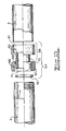
- a prior art adaptor fitting 1 is used to make a connection between the hot water outlet 2 and a conventional copper pipe 3.
- both the hot water outlet 2 and the copper pipe 3 are 3 ⁇ 4 inch (DN20 which is a nominal diameter (external) of 20mm).
- DN20 3 ⁇ 4 inch
- other pipe sizes are possible.
- DN15 1 ⁇ 2 inch (DN15) copper pipe can be connected to a 3 ⁇ 4 inch (DN20) inlet or outlet.
- the size of each end of the fitting is determined by the nominal diameter (external) of the pipe with which that end of the fitting connects.
- the New Zealand practice, and the practice in some other jurisdictions is to regard the internal diameter of the pipe as the nominal pipe or fitting size.
- the adaptor fitting 1 has a conventional pipe coupling 5 which in the present case is an olive compression fitting which takes the form of a copper annular olive 6, a nut 7 and a male thread 8.
- the interior of the male thread 8 has a machined cavity 11 which terminates in a shoulder 12 and which has an internally chamfered opening 13.
- An equivalent internal chamfer 14 is provided on the nut 7 and these two chamfers 13, 14 mate with equivalent chamfers 23, 24 on the olive 6. All chamfers 13, 14, 23 and 24 have the same slope and the same diameter.
- This conventional pipe coupling operates as follows.
- the nut 7 and olive 6 are slid onto the copper pipe 3 and the copper pipe 3 is inserted into the machined cavity 11 so that the end of the pipe 3 abuts the shoulder 12.
- the thread of the nut 7 is engaged with the male thread 8 so as to compress the olive 6 between the chamfers 13 and 14. In this way the internal diameter of the olive 6 is reduced and forms a seal with the exterior of the pipe 3.
- the other end of the adaptor fitting 1 consists of a female thread 18 which is provided with an annular base 17.
- a washer or gasket 16 may be provided in some circumstances.
- the female thread 18 and the male thread 8 are positioned at either end of a through bore 10.
- fastening threads consist of a parallel male thread and a parallel female thread and the seal is intended to be effected by means of a washer or gasket. It is intended that no sealing tape or sealing compound is normally used with fastening threads. However, because of the poor quality and accuracy of many fastening threads, sealing tape or thread sealant is often used.
- sealing threads consist of a tapered male thread which engages with a parallel female thread, the seal being brought about by the metal to metal engagement of the tapered and parallel threads.
- thread tape or a thread sealant compound is invariably used with sealing threads.
- a first problem which arises with the adaptor fitting 1 of Fig. 1 is that the extent of the engagement between the parallel female thread 18 and parallel male thread of the hot water outlet 2, may be insufficient to compress the gasket 16 between the annular base 17 and the end of the hot water outlet 2.
- the efficiency of the seal cannot be assessed until the water is turned on and the system is pressurised to detect any leaks.
- This extent of thread engagement, and hence degree of gasket compression, if any, is very dependent upon the quality and machining accuracy of the two parallel threads. Because of this possibility of incomplete compression, it is necessary to use sealing tape, or thread sealant, on the threads of the hot water outlet so as to give some prospect of an effective seal between the hot water outlet 2 and the female thread 18.
- a conventional instantaneous gas water heater 30 has a gas inlet fitting 31, a hot water outlet fitting 32 and a cold water inlet fitting 33. Normally when viewed from the front, the hot water outlet fitting 32 is on the left, the gas inlet fitting 31 is on the right, and the cold water inlet fitting 33 is in the middle.
- Isolation valves 28 and 29 as described in the abovementioned patent are installed onto the gas inlet fitting 31 and cold water inlet fitting 33 utilising the nut and tail fitting 35 of the valves 28, 29.
- the valves 28, 29 incorporate one of various types of pipe coupling which enable the valves to be connected to the gas pipe 41 and the cold water pipe 43.
- the nuts 35 of the valves 28, 29 are backed off so as to disengage same from the gas inlet 31 and cold water inlet 33. This provides an immediate disconnection between the valves and the inlets as illustrated, with the washer 26 which provides the seal between the valves and the inlets in each instance being shown clear of the nut 35 in Fig. 2 for clarity.
- a similar problem in relation to bowing or springing of the pipe 3 occurs even if the adaptor fitting 1 were to be modified so as to use one of the other types of pipe couplings. That is, irrespective of whether the adaptor fitting 1 has an olive compression pipe coupling as illustrated, or a flared compression pipe coupling or a CONETITE type pipe coupling, because of an overlapping engagement between the pipe and the coupling, removal of the heater can only be achieved by moving the heater upwardly in the vertical direction. Thus movement of the heater in the horizontal plane is either impossible, or extremely difficult.
- the adaptor fitting 1 is unscrewed from the hot water outlet 32 and reused by being screwed onto the hot water outlet 32 of the new heater which is to be installed. Because the heater is heavy, it is normally firstly installed onto the previous heater's existing mounting connections. It is then necessary for the pipe 3 to be sprung or bowed again (with its attendant risks) whilst the new heater has its inlets and outlet re-connected to the existing pipework. This requires the upper end of the copper pipe 3 to be re-seated in the pipe coupling of the adaptor fitting 1. Only then can the nut 7 be retightened onto the male thread 8 so as to re-compress the copper olive 6, or the equivalent tightening procedure be carried out for the other types of pipe coupling.
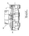
- the plumbing adaptor fitting 51 of the preferred embodiment is illustrated, as are the hot water outlet fitting 2 and copper pipe 3 as before.
- the plumbing adaptor fitting 51 has a pipe coupling 55 at one end which, in this embodiment, takes the form of an olive compression coupling.
- the other end of the plumbing adaptor fitting 51 is provided with a loose nut 67 which has an internal female thread 68 and an interior annular rim 69.
- the adaptor fitting 51 has a through bore 70 which terminates in a flange 71.
- the flange 71 mates with a washer or gasket 76 and, in addition, has an external diameter sufficient to cause the annular rim 69 to abut the flange 71 and thereby retain the loose nut 67 on the plumbing adaptor fitting 51.
- the flange 71 is provided with two machined edges 72, 73 which enable the loose nut 67, when tilted at the correct angle, to be slipped onto the plumbing adaptor fitting 51.
- the loose nut 67 is only able to be slipped off the plumbing adaptor fitting 51 if the loose nut 67 is carefully aligned with the flange 71 so as to reverse the installation procedure. In practice, the loose nut 67 remains installed on the plumbing adaptor fitting 51.
- the plumbing adaptor fitting 51 is easily installed onto the hot water outlet fitting 2 by engaging the threads 68 on the loose nut 67 with the thread on the hot water outlet fitting 2, thereby compressing the gasket 76 between the end of the hot water outlet fitting 2 and the flange 71.
- the length of the thread on the outlet fitting 2 always greatly exceeds the axial length of the loose nut 67.
- an effective seal is able to be easily made without the use of any sealing tape or sealing compound.
- the efficiency of this seal is independent of the skill of the installing plumber since the loose nut 67 will always be tightened sufficiently to compress the gasket 76.
- Fig. 5 the advantages of the preferred embodiment will now be described in a manner similar to the description of Fig. 2 .
- the gas heater 30, gas inlet 31, hot water outlet 32, cold water inlet 33, valves 28 and 29, and gas pipe 41, cold water pipe 43 and hot water outlet pipe 3 are as before.
- the isolation valves 28 and 29 are closed and the loose nuts 35 of the nut and tail fittings thereof are backed off from the gas inlet fitting 31 and cold water inlet fitting 33 respectively.
- the washers or gaskets 26 present between the inlets fittings 31, 33 and the valves 28, 29 are shown above the nuts 35 to render them visible.
- the gas water heater 30 can be moved not only in the vertical direction Z but also moved away in the horizontal plane defined by the XY axes illustrated in Fig. 5 . As a consequence, the gas water heater 30 can be moved horizontally without lifting and without bowing or springing any of the pipes 3, 41 and 43. This greatly assists the ease both of removal of an old heater and the installation of a replacement heater.
- a further advantage of the arrangement illustrated in Figs. 3 and 5 is that the length of the plumbing adaptor fitting 51 from the front face of the compressed gasket 76 to the shoulder 12 (see Fig . 1 ) of the machined cavity 11, is fixed and known beforehand. As a consequence, the plumber is able to measure from the free end fitting 2 and determine exactly where to cut the pipe 3 to the correct length. This greatly simplifies the heater installation procedure. Furthermore, many plumbers do repeated installations and/or multiple installations as illustrated in Fig. 14 , so the time and convenience efficiencies arising from this known fixed length accumulate.
- valves 28, 29 and the plumbing adaptor fitting 51 can be placed in a box or other container and sold as a kit.
- Fig. 6 illustrates a tap connector 101 which has a copper capillary coupling 105 at one end and a loose nut 107 at the other end.
- the tap connector 101 is fabricated in two parts 102, 103 which are brazed, or soldered, together during manufacture. As a consequence, there is an external joint 104 visible as a result of this manufacturing technique which is labour intensive and therefore expensive. It is necessary to manufacture the fitting in two parts, 102 and 103 to enable the installation or mounting of the loose nut 107 onto the part 103 prior to permanently joining the two parts.
- the part 103 is provided with a frusto-conical spigot 108 which mates with a corresponding tapered opening 113 of a machined outlet 115.
- the machined outlet 115 has external threads 118 which engage with the internal threads 119 of the nut 107. The engagement of the threads 118, 119 draws the spigot 108 into metal to metal contact with the tapered opening 113 thereby bringing about a metal to metal seal.
- the tap connector 101 is of no use in relation to gas heaters, and equivalent appliances, because the hot water outlet fitting 32, for example, does not have any tapered opening 113.
- a similar prior art device in the form of a straight union connector 121 is illustrated.
- the connector 121 has a loose nut 127 which slides over a capillary fitting 125. The loose nut is unrestrained and thus is liable to get lost or misplaced prior to any attempted installation or use.
- the connector 121 has an exterior annular flange 122 and a spigot 128 which is essentially the same as the spigot 108 of Fig. 6 .
- the machined outlet 115 is as in Fig. 6 also.
- the seal between the spigot 128 and the machined outlet 115 is as in Fig. 6 .
- the straight union connector 121 of Fig. 7 is of no assistance in relation to hot water services since the appliance does not have an inlet or outlet with a machined taper 113.
- the outlet fitting 2 loose nut 67, thread 68, annular rim 69, bore 70, flange 71 and washer 76 are as in Fig 3 .
- the pipe coupling 56 is a flared compression coupling
- the pipe coupling 57 is a CONETITE coupling
- the coupling 58 is a copper capillary coupling.
- the pipe couplings 56 and 57 are shown with the compression nuts screwed onto the fitting to indicate how the plumbing adaptor fitting is normally presented for sale.
- the copper capillary coupling 58 of Fig. 10 is formed by a machined cavity 61 having a shoulder 62.
- the copper pipe 3 is inserted into the machined cavity 61 so that the end of the copper pipe 3 abuts the shoulder 62 and then the plumbing adaptor fitting 54 and the copper pipe 3 are brazed or silver soldered together.
- the plumbing adaptor fitting 54 is able to be used together with a copper capillary coupling 58 since the loose nut 67 means that the adaptor 54 never needs to be disconnected from the pipe 3.
- a particular advantage of the loose nut 67 and flange 71 is that the body of the adaptor 51-54 can be fabricated in a single piece. This means that there are no manufacturer implemented threaded joins or joints in the body of the adaptor.
- the housing of the valve includes two manufacturer implemented threaded joins.
- the first of these is the structural threaded join which brings together the two parts of the valve housing.
- the second of these manufactured joins occurs with the screwed connection of the tail of the loose nut and tail.
- the loose nut is placed on the tail and then the tail is screwed into the valve. This permanently retains the loose nut of the nut and tail fitting.
- Figs. 11-13 respectively illustrate three different valve embodiments 78, 88 and 98 each having such a loose nut 67 and flange 71 and having different mechanical pipe couplings which are respectively an olive compression coupling 55, a flared compression coupling 56, and a CONETITE compression coupling 57.
- a copper capillary coupling is not recommended for a valve since the heat involved in brazing or silver soldering may well render the internal O-rings of the valve inoperable, or of reduced life expectancy. Since for the valves 78, 88 and 98 this second manufacturer implemented join is eliminated, the cost of manufacturing the valves of Figs. 11-13 is reduced.
- a number of heaters are connected in parallel or via a manifold.
- Such an arrangement is illustrated in Fig. 14 where three heaters 30 are provided and all are controlled by means of two conventional in-line valves 128,129.
- all the inlet and outlet fittings 1, 2, 3 are connected to a corresponding plumbing adaptor fitting 51-54 (the choice of plumbing adaptor fitting will be dictated by whether the connection is for gas 52 and 54 or water 51-54 inclusive).
- the three heaters 30 require only two valves but nine plumbing adaptor fittings. Accordingly, whilst with a single heater the plumbing adaptor fitting 51-54 is connected to the hot water outlet only, with multiple heaters the plumbing adaptor fittings 51-54 can be connected to gas or cold water inlet fittings as appropriate.
- the plumbing adaptor fittings 51-54 can be provided with a plastic cap to retain the washer 76 within the loose nut 67. The cap is discarded at installation.
- the plumbing adaptor fitting complies with the requirements of Australian Standard AS 3688 and the valves comply with the requirements of Australian Standard ATS 5200.012 (or equivalent water standard) and/or AS 4617 (or equivalent gas standard).
Landscapes
- Engineering & Computer Science (AREA)
- General Engineering & Computer Science (AREA)
- Mechanical Engineering (AREA)
- Valve Housings (AREA)
- Branch Pipes, Bends, And The Like (AREA)
- Pipe Accessories (AREA)
- Quick-Acting Or Multi-Walled Pipe Joints (AREA)
Applications Claiming Priority (1)
| Application Number | Priority Date | Filing Date | Title |
|---|---|---|---|
| AU2011903123A AU2011903123A0 (en) | 2011-08-05 | Plumbing Adaptor Fitting |
Publications (1)
| Publication Number | Publication Date |
|---|---|
| EP2554889A1 true EP2554889A1 (de) | 2013-02-06 |
Family
ID=45439807
Family Applications (1)
| Application Number | Title | Priority Date | Filing Date |
|---|---|---|---|
| EP12005636A Withdrawn EP2554889A1 (de) | 2011-08-05 | 2012-08-02 | Sanitäranschluss-Adapter |
Country Status (3)
| Country | Link |
|---|---|
| EP (1) | EP2554889A1 (de) |
| CN (1) | CN102913698B (de) |
| AU (2) | AU2011101101B4 (de) |
Cited By (6)
| Publication number | Priority date | Publication date | Assignee | Title |
|---|---|---|---|---|
| JP2014228064A (ja) * | 2013-05-22 | 2014-12-08 | 三菱重工業株式会社 | ユニオン管継手、及びこれを備えているキャンドモータポンプ |
| JP2016114179A (ja) * | 2014-12-16 | 2016-06-23 | 未来工業株式会社 | 通気弁付継手 |
| WO2018042465A1 (en) * | 2016-09-02 | 2018-03-08 | Nikles Tec Italia S.R.L. | Aerator |
| CN108916511A (zh) * | 2018-08-06 | 2018-11-30 | 苏州欧圣电气股份有限公司 | 连通管组件及空压机 |
| PL126742U1 (pl) * | 2017-10-30 | 2019-05-06 | Budzynski Adam | Złącze przewodów rurowych |
| US12581893B2 (en) | 2021-07-28 | 2026-03-17 | Ichor Systems, Inc. | Modular fitting assembly and system incorporating same |
Families Citing this family (11)
| Publication number | Priority date | Publication date | Assignee | Title |
|---|---|---|---|---|
| EP3016611B1 (de) * | 2013-07-05 | 2022-06-08 | Iniziativa Centro Sud S.r.L. | Anschlusselement zum anschluss eines wasserbetriebenen gerätes an einen wasserhahn |
| CN104455884A (zh) * | 2014-11-11 | 2015-03-25 | 贵州黔南科技塑业有限公司 | 一种快速连接管接头 |
| US10077112B2 (en) * | 2015-12-16 | 2018-09-18 | Hamilton Sundstrand Corporation | Cabin supply duct |
| CN109140068A (zh) * | 2017-06-16 | 2019-01-04 | 科勒(中国)投资有限公司 | 内外螺纹通用接头、管道、方法及马桶 |
| CN112639348B (zh) * | 2018-08-30 | 2023-04-25 | 日本皮拉工业株式会社 | 流路接头构造 |
| CN109114321A (zh) * | 2018-10-23 | 2019-01-01 | 黄子颢 | 一种管道连接组件及管道 |
| CN110806117A (zh) * | 2019-10-23 | 2020-02-18 | 大唐甘肃发电有限公司八〇三热电厂 | 一种热电厂多方位可拆装的循环水系统 |
| CN215111093U (zh) * | 2021-06-11 | 2021-12-10 | 浙江盾安禾田金属有限公司 | 防拆连接件 |
| EP4354002A4 (de) * | 2021-06-11 | 2025-05-28 | Zhejiang Dunan Artificial Environment Co., Ltd. | Verbinder zur verhinderung von zerlegungen |
| CN114484115A (zh) * | 2022-03-01 | 2022-05-13 | 广西玉柴机器股份有限公司 | 一种方向可调的旋转接头及方法 |
| CN115468046B (zh) * | 2022-09-23 | 2025-03-28 | 中建三局绿色产业投资有限公司 | 一种排水管道接头 |
Citations (7)
| Publication number | Priority date | Publication date | Assignee | Title |
|---|---|---|---|---|
| GB1537035A (en) * | 1976-03-26 | 1978-12-29 | Sealed Motor Constr Co Ltd | Tubular body with connecting ring |
| GB2135415A (en) * | 1983-02-23 | 1984-08-30 | Plastiers Ltd | Pipe coupler-plastic pipes |
| DE8530138U1 (de) * | 1985-10-24 | 1985-12-12 | Gebrüder Kemper GmbH + Co Metallwerke, 5960 Olpe | Anschlußstück |
| AU2006200845A1 (en) | 2006-02-28 | 2006-03-23 | Zetco Valves Pty Ltd | Plumbing Arrangements & Fittings |
| US20090146418A1 (en) | 2007-12-10 | 2009-06-11 | Nibco Inc. | Connection with tail piece for a press-fitting |
| EP2128508A2 (de) * | 2008-05-29 | 2009-12-02 | Teco S.r.l. | Flüssigkeitsabsperrvorrichtung |
| US20110115220A1 (en) | 2009-11-19 | 2011-05-19 | Kuang Ming Kuo | Tube coupling device |
Family Cites Families (3)
| Publication number | Priority date | Publication date | Assignee | Title |
|---|---|---|---|---|
| CN2071739U (zh) * | 1990-07-28 | 1991-02-20 | 朱云岐 | 一种带活节的阀门联接装置 |
| CN201050649Y (zh) * | 2007-06-11 | 2008-04-23 | 庞舜源 | 一种金属管平边连接管件 |
| CN201045421Y (zh) * | 2007-06-22 | 2008-04-09 | 吴江 | 太阳能热水器三通调控阀 |
-
2011
- 2011-08-29 AU AU2011101101A patent/AU2011101101B4/en not_active Expired
-
2012
- 2012-07-30 AU AU2012208986A patent/AU2012208986B2/en active Active
- 2012-08-02 EP EP12005636A patent/EP2554889A1/de not_active Withdrawn
- 2012-08-06 CN CN201210284409.1A patent/CN102913698B/zh active Active
Patent Citations (7)
| Publication number | Priority date | Publication date | Assignee | Title |
|---|---|---|---|---|
| GB1537035A (en) * | 1976-03-26 | 1978-12-29 | Sealed Motor Constr Co Ltd | Tubular body with connecting ring |
| GB2135415A (en) * | 1983-02-23 | 1984-08-30 | Plastiers Ltd | Pipe coupler-plastic pipes |
| DE8530138U1 (de) * | 1985-10-24 | 1985-12-12 | Gebrüder Kemper GmbH + Co Metallwerke, 5960 Olpe | Anschlußstück |
| AU2006200845A1 (en) | 2006-02-28 | 2006-03-23 | Zetco Valves Pty Ltd | Plumbing Arrangements & Fittings |
| US20090146418A1 (en) | 2007-12-10 | 2009-06-11 | Nibco Inc. | Connection with tail piece for a press-fitting |
| EP2128508A2 (de) * | 2008-05-29 | 2009-12-02 | Teco S.r.l. | Flüssigkeitsabsperrvorrichtung |
| US20110115220A1 (en) | 2009-11-19 | 2011-05-19 | Kuang Ming Kuo | Tube coupling device |
Cited By (6)
| Publication number | Priority date | Publication date | Assignee | Title |
|---|---|---|---|---|
| JP2014228064A (ja) * | 2013-05-22 | 2014-12-08 | 三菱重工業株式会社 | ユニオン管継手、及びこれを備えているキャンドモータポンプ |
| JP2016114179A (ja) * | 2014-12-16 | 2016-06-23 | 未来工業株式会社 | 通気弁付継手 |
| WO2018042465A1 (en) * | 2016-09-02 | 2018-03-08 | Nikles Tec Italia S.R.L. | Aerator |
| PL126742U1 (pl) * | 2017-10-30 | 2019-05-06 | Budzynski Adam | Złącze przewodów rurowych |
| CN108916511A (zh) * | 2018-08-06 | 2018-11-30 | 苏州欧圣电气股份有限公司 | 连通管组件及空压机 |
| US12581893B2 (en) | 2021-07-28 | 2026-03-17 | Ichor Systems, Inc. | Modular fitting assembly and system incorporating same |
Also Published As
| Publication number | Publication date |
|---|---|
| AU2011101101B4 (en) | 2011-12-22 |
| CN102913698B (zh) | 2016-12-21 |
| AU2012208986B2 (en) | 2016-09-22 |
| NZ601244A (en) | 2014-01-31 |
| AU2012208986A1 (en) | 2013-02-21 |
| CN102913698A (zh) | 2013-02-06 |
| AU2011101101A4 (en) | 2011-09-29 |
Similar Documents
| Publication | Publication Date | Title |
|---|---|---|
| AU2012208986B2 (en) | Plumbing Adaptor Fitting | |
| US9683685B2 (en) | Plumbing fitting assemblies | |
| US7942161B2 (en) | Push-fit valve with integrated mounting assembly | |
| US9879810B2 (en) | Push-to-connect joint assembly with protective shield device and method | |
| EP3117154B1 (de) | Verbindungsanordnung | |
| US5857717A (en) | Plumbing device and method | |
| JP6031032B2 (ja) | ウエルドレスアルミニウム製hvacシステム | |
| US20030205281A1 (en) | Field configurable shut-off valve | |
| US20240392901A1 (en) | Tight-seal piping component | |
| CA2110129C (en) | Plastic inlet appliance water valve | |
| US20050230650A1 (en) | Irrigation valve assembly | |
| US4691726A (en) | Method and apparatus for valve assembly for a hot water tank | |
| US20140339818A1 (en) | Connection system for pipes in refrigeration plants | |
| NZ601244B (en) | Plumbing adaptor fitting | |
| CN204328273U (zh) | 一种油管与管接头的连接锁紧结构 | |
| AU2010101162A4 (en) | Improvements in Relation to Valves | |
| US20030197379A1 (en) | Multi-sealing compression fitting for plumbing connections | |
| KR102524349B1 (ko) | 배관연결구조 및 배관연결방법 | |
| CN212480215U (zh) | 一种制冷用卡压式球阀 | |
| KR101397464B1 (ko) | 배관 연결기구 | |
| US11549621B2 (en) | Fluid connector | |
| CN105371025A (zh) | 防漏型管路连接体系 | |
| AU2011100872A4 (en) | Improvements in Relation to Valves | |
| US20090039645A1 (en) | Fitting and tube assembly for refrigeration systems | |
| AU2007203650A1 (en) | Combination Plumbing Fitting |
Legal Events
| Date | Code | Title | Description |
|---|---|---|---|
| PUAI | Public reference made under article 153(3) epc to a published international application that has entered the european phase |
Free format text: ORIGINAL CODE: 0009012 |
|
| AK | Designated contracting states |
Kind code of ref document: A1 Designated state(s): AL AT BE BG CH CY CZ DE DK EE ES FI FR GB GR HR HU IE IS IT LI LT LU LV MC MK MT NL NO PL PT RO RS SE SI SK SM TR |
|
| AX | Request for extension of the european patent |
Extension state: BA ME |
|
| 17P | Request for examination filed |
Effective date: 20130801 |
|
| RBV | Designated contracting states (corrected) |
Designated state(s): AL AT BE BG CH CY CZ DE DK EE ES FI FR GB GR HR HU IE IS IT LI LT LU LV MC MK MT NL NO PL PT RO RS SE SI SK SM TR |
|
| 17Q | First examination report despatched |
Effective date: 20180511 |
|
| STAA | Information on the status of an ep patent application or granted ep patent |
Free format text: STATUS: THE APPLICATION IS DEEMED TO BE WITHDRAWN |
|
| 18D | Application deemed to be withdrawn |
Effective date: 20200206 |