EP2554904B1 - Dispositif de chambre de combustion ou dispositif de chambre de poussée - Google Patents
Dispositif de chambre de combustion ou dispositif de chambre de poussée Download PDFInfo
- Publication number
- EP2554904B1 EP2554904B1 EP12179345.9A EP12179345A EP2554904B1 EP 2554904 B1 EP2554904 B1 EP 2554904B1 EP 12179345 A EP12179345 A EP 12179345A EP 2554904 B1 EP2554904 B1 EP 2554904B1
- Authority
- EP
- European Patent Office
- Prior art keywords
- wall means
- chamber device
- combustion chamber
- fibers
- accordance
- Prior art date
- Legal status (The legal status is an assumption and is not a legal conclusion. Google has not performed a legal analysis and makes no representation as to the accuracy of the status listed.)
- Active
Links
Images

Classifications
-
- F—MECHANICAL ENGINEERING; LIGHTING; HEATING; WEAPONS; BLASTING
- F23—COMBUSTION APPARATUS; COMBUSTION PROCESSES
- F23R—GENERATING COMBUSTION PRODUCTS OF HIGH PRESSURE OR HIGH VELOCITY, e.g. GAS-TURBINE COMBUSTION CHAMBERS
- F23R3/00—Continuous combustion chambers using liquid or gaseous fuel
- F23R3/002—Wall structures
-
- F—MECHANICAL ENGINEERING; LIGHTING; HEATING; WEAPONS; BLASTING
- F23—COMBUSTION APPARATUS; COMBUSTION PROCESSES
- F23M—CASINGS, LININGS, WALLS OR DOORS SPECIALLY ADAPTED FOR COMBUSTION CHAMBERS, e.g. FIREBRIDGES; DEVICES FOR DEFLECTING AIR, FLAMES OR COMBUSTION PRODUCTS IN COMBUSTION CHAMBERS; SAFETY ARRANGEMENTS SPECIALLY ADAPTED FOR COMBUSTION APPARATUS; DETAILS OF COMBUSTION CHAMBERS, NOT OTHERWISE PROVIDED FOR
- F23M5/00—Casings; Linings; Walls
- F23M5/08—Cooling thereof; Tube walls
-
- F—MECHANICAL ENGINEERING; LIGHTING; HEATING; WEAPONS; BLASTING
- F23—COMBUSTION APPARATUS; COMBUSTION PROCESSES
- F23M—CASINGS, LININGS, WALLS OR DOORS SPECIALLY ADAPTED FOR COMBUSTION CHAMBERS, e.g. FIREBRIDGES; DEVICES FOR DEFLECTING AIR, FLAMES OR COMBUSTION PRODUCTS IN COMBUSTION CHAMBERS; SAFETY ARRANGEMENTS SPECIALLY ADAPTED FOR COMBUSTION APPARATUS; DETAILS OF COMBUSTION CHAMBERS, NOT OTHERWISE PROVIDED FOR
- F23M2900/00—Special features of, or arrangements for combustion chambers
- F23M2900/05004—Special materials for walls or lining
Definitions
- the invention relates to a combustion chamber device or thrust chamber device.
- a combustion chamber comprising an outer jacket and an inner jacket which delimits a combustion chamber and which is fluid-permeable for effusion cooling or transpiration cooling is known, the inner jacket comprising a plurality of disk elements following one another along an axial axis.
- a nozzle extension for an engine is known, with a nozzle jacket that delimits a flow cross-section which expands from a nozzle extension inlet to a nozzle extension outlet, the nozzle extension inlet being connectable to a combustion chamber outlet of a combustion chamber of an engine, and the nozzle jacket being at least two made of a ceramic fiber composite material has produced, relatively fixed shell elements.
- a thrust chamber device comprising a shell element made of a ceramic matrix material, which has an inner wall, an outer wall and a plurality of cooling channels, the cooling channels being arranged between the inner wall and the outer wall and wherein fibers are inserted into the ceramic matrix material Reinforcement of the shell element are embedded.
- a fuel is burned with an oxidizer and a thrust can be generated via combustion gases.
- a combustion chamber device is a specific example of a thrust chamber device.
- a thrust can be generated by gases, even if there is no combustion, for example by heating a gas in another way such as nuclear.
- the invention is based on the object of providing a combustion chamber device with high structural stability and high temperature resistance.
- a first wall device which delimits a combustion chamber or a thrust chamber with an inner side
- a second wall device is provided, the inner side of which faces an outer side of the first wall device
- the first being Wall device is made of a ceramic composite material
- a cooling channel device for cooling the first wall device with a cooling fluid which comprises at least one cooling channel which is arranged on the first wall device and / or the second wall device and / or between the first wall device and the second wall device or is formed, is provided, wherein fibers of high thermal conductivity are arranged in the first wall device, which are arranged away from the inside in the direction of heat transport and which have a thermal conductivity of at least 100 W / mK, with fiber ends of the fibers of high thermal conductivity ending at or near the inside of the first wall device, wherein the fibers of high thermal conductivity are led from the inside of the first wall device to the at least one channel and wherein fiber ends of the fibers of high thermal conductivity end at
- a ceramic composite material such as, for example, a carbide-ceramic material or an oxide-ceramic material basically has a high temperature resistance.
- the material has a relatively low coefficient of thermal expansion in comparison to a metallic material. If the first wall device is correspondingly thick, then it is structurally stable accordingly and a high temperature can be achieved on a hot gas side. As a result, a high temperature gradient can arise over the first wall device. However, this can lead to high thermal stresses with the corresponding material problems.
- targeted heat conduction paths are provided via fibers of high thermal conductivity arranged in the first heat conduction device. As a result, heat can be effectively decoupled from the inside of the first wall device into the cooling channel device, a cooling fluid such as hydrogen then ensuring regenerative cooling. A high cooling efficiency can thereby be achieved with high structural integrity.
- the fibers of high thermal conductivity have a thermal conductivity (in particular integral thermal conductivity) of at least 100 W / mK, preferably at least 300 W / mK, and in particular up to over 600 W / mK. This enables effective heat dissipation to be achieved.
- the fibers of high thermal conductivity are protected in the matrix of the ceramic composite material.
- Fiber ends of the fibers of high thermal conductivity end at or in the vicinity of the inside of the first wall device. This allows effective heat conduction paths along the corresponding fibers provide. Furthermore, for example, the inside can then be easily abraded and a homogeneous, rough surface can be obtained, which in turn is a good carrier for a coating.
- the fibers of high thermal conductivity are led from the inside of the first wall device to the at least one channel. This allows heat to be dissipated effectively into a channel in which a cooling fluid flows.
- Fiber ends of the fibers of high thermal conductivity end at a flow space or in the vicinity of a flow space of the at least one channel. This provides an effective heat conduction path over a fiber.
- the at least one channel advantageously has a direction of extent which is at least approximately parallel to an axial axis of the first wall device. It is advantageous if a cooling fluid is guided counter to a main flow direction in the combustion chamber or thrust chamber. This enables effective cooling using the countercurrent principle. Furthermore, for example, a cooling fluid, which is then used as fuel, can be preheated.
- fibers of high thermal conductivity are aligned at least approximately in the radial direction with respect to an axial axis of the first wall device.
- first wall device has a uniform thickness, a heat conduction path of minimized length can be provided and heat can thereby be dissipated effectively.
- Not all fibers have to be aligned radially.
- the majority of the fibers (for example more than 70%) are aligned at least approximately radially.
- the first wall device is designed in particular as an inner liner.
- the second wall device surrounds the first wall device.
- the second wall device is designed in particular as an outer liner.
- a plurality of cooling channels which are spaced apart in a circumferential direction, are formed on the first wall device in the area of the outside.
- the cooling channels are thereby integrated into the first wall device, which in particular then has a meandering course on its circumference.
- cooling channels are arranged so as to be uniformly distributed in the circumferential direction. As a result, uniform cooling can be achieved over the entire surface of the first wall device.
- a thermal blocking device is arranged between the first wall device and the second wall device, in particular if the second wall device would be in direct thermal contact without a thermal blocking device.
- the thermal barrier device is made of a material with low thermal conductivity. It can thereby be prevented that a heat conduction path leads from the first wall device directly into the second wall device.
- the thermal barrier device itself can be made porous, for example, in order to achieve transpiration cooling there via cooling fluid, for example.
- the thermal barrier device is formed, for example, by a (surface) coating or a tubular element.
- the thermal blocking device is formed by at least one tubular element. This tubular element can be arranged over the first wall device in order to obtain an effective thermal decoupling from the second wall device.
- the fibers of high thermal conductivity are C fibers. These fibers are retained in the first wall device, that is, they lie C-paths in the ceramic material from the inside to the outside, which are continuous and uninterrupted.
- the first wall device has a plurality of segments arranged axially one behind the other. In this way, for example, a rotationally symmetrical combustion chamber can be produced in a simple manner. It is referred to in this context to the EP 1 748 253 A2 referred to, which are expressly referred to.
- adjacent segments have different fiber orientations in a fiber reinforcement matrix.
- a first wall device which has a high thermal resistance with low thermal expansion.
- segments or segment groups are positioned axially braced in the second wall device.
- a corresponding combustion chamber device can thereby be produced in a simple manner.
- the first wall device is designed to be at least partially fluid-impermeable. This enables regenerative cooling to be achieved in an effective way.
- the cooling fluid absorbs heat and dissipates it. With a partial fluid permeability through the provision of corresponding channels or pores, a transpiration cooling effect can be achieved at certain points.
- cooling fluid films can form locally in the combustion chamber on the first wall device. In this way, for example, the wall friction and the wall heat transfer can be reduced locally.
- Fluid impermeability can be achieved, for example, in that the first wall device has a fluid-impermeable coating on the outside.
- a copper coating is provided.
- the material of the first wall device it is possible for the material of the first wall device to have closed pores or to be pore-free. During the production of the first wall device, it is ensured that it is free of pores or that the pores that have arisen are closed by appropriate impregnation.
- a volume fraction of fibers of high thermal conductivity of the first wall device reaches at least 30%, in particular at least 40%, in particular at least 50%, preferably at least 60% and preferably at least 65% or at least 70%.
- a high integral thermal conductivity of, for example, more than 300 W / mK can be achieved through the first wall device.
- the combustion chamber or thrust chamber is advantageously designed to be rotationally symmetrical to an axial axis. This results in effective flow conditions.
- the first wall device is made in particular from a carbide-ceramic or oxide-ceramic material or a highly thermally conductive carbon material (such as C / C).
- the carbide-ceramic material can be, for example, a C-XC or C / C-XC carbide material, where X is a carbide former such as silicon.
- the second wall device is made from a fiber composite material.
- the combustion chamber device can thereby be produced with a low weight.
- the first wall device is coated on the inside.
- a material with high temperature resistance and the highest possible thermal conductivity is used as the coating material. This avoids "hot spots" with the corresponding material problems.
- a ceramic material is used. As a result, a higher temperature gradient can be built up over the first wall device in order to ensure effective heat transport.
- the first wall device is coated on the outside.
- the first wall device can be made impervious to fluid. It is thereby also possible, if a material of high thermal conductivity, such as a metallic material such as copper, is used as the coating material, to ensure uniform heat distribution on the outside of the first wall device.
- Cooling fluid Hydrogen or methane, for example, is used as the cooling fluid.
- the correspondingly preheated cooling fluid can then be used as fuel.
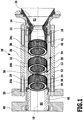
- a first embodiment of a combustion chamber device which is shown schematically in a sectional view in Figure 1 and is designated there by 10, comprises a combustion chamber designated as a whole by 12.
- the combustion chamber has a combustion chamber 14.
- This combustion chamber 14 is designed, in particular, to be rotationally symmetrical to an axial axis 16.
- a suitable injector device 46, through which fuel and oxidizer can be blown into the combustion chamber 14, is assigned to the combustion chamber 12. Combustion takes place in the combustion chamber 14 to generate the corresponding thrust.
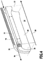
- the combustion chamber device 10 has a nozzle device 18 which is located in a main flow direction 20 (cf. Figure 4 ) connects to the combustion chamber.
- the nozzle device 18 has a nozzle chamber 22 which is designed to be rotationally symmetrical with an axis which is coaxial with the axial axis 16.
- the nozzle device 18 has a cross-sectional constriction 24 in comparison to the cross-section of the combustion chamber 14, which is followed by an enlargement 26. A corresponding thrust is generated via the nozzle device 18 by means of combustion gases produced during the combustion.
- a combustion chamber device is a special case of a thrust chamber device.
- a thrust chamber device can generate thrust, although combustion does not necessarily have to take place to generate thrust.
- gases in a thrust chamber of a thrust chamber device can be heated via nuclear decay processes.
- the combustion chamber and the thrust chamber are basically of the same design.
- the combustion chamber 12 comprises a first wall device 28.
- the first wall device is made of a ceramic composite material (CMC material; Ceramic Matrix Composite Material).
- the first wall device 28 has an inner side 30 which delimits the combustion chamber 14. It also has an outer side 32 opposite the inner side.
- the first wall device 28 extends along the axial axis 16. It is designed to be closed along this axial axis 16. In Figure 1 For reasons of illustration, three segment groups 34a, 34b, 34c are shown as not connected. In fact, the individual segment groups are connected to one another so that the first wall device 28 forms an inner liner (inner shell) for the combustion chamber 14.
- the segment groups can be permanently connected to one another, for example by gluing or ceramic joining, or they can be releasably connected to one another; for example, they can be clamped using an axial clamping pressure.
- the combustion chamber device 10 comprises a second wall device 36, which is designed to be closed and surrounds the first wall device 28.
- the second wall device 36 has an inner side 38 which faces the outer side 32 of the first wall device 28. It also has an outer side 40 opposite the inner side 38.
- the second wall device 36 is an outer liner (outer shell) of the combustion chamber device 10.
- the combustion chamber 12 with the first wall device 28 is arranged in the second wall device 36, which is designed to be closed.
- the first wall device 28 sits between an end face 42 of the nozzle device 18 and an end face 44 of an injector device 46.
- the injector device 46 is in turn held by a flange 48 which is fixed to the second wall device 36 via connecting elements 50 such as bolts or the like.
- the end faces 42 and 44 are designed in particular as annular surfaces. The first wall device 28 sits axially clamped between these.
- the material of the first wall device 28 has a lower (in particular significantly lower) modulus of elasticity in the axial direction compared to a radial direction 52 perpendicular thereto.
- a type of axial “spring effect” can thereby be achieved and the first wall device 28 can be pretensioned axially between the end faces 42 and 44.
- the first wall device 28 can thereby be pushed in loosely and a mechanical decoupling from the second wall device can also be achieved.
- a cooling channel device designated as a whole with 54 which comprises one or more cooling channels 56 through which a cooling channel fluid can flow past the outside 32 of the first wall device 28 in order to achieve regenerative cooling of the first wall device 28.
- the cooling channel 56 or the cooling channels 56 are formed as recesses on the second wall device 36 on its inner side 38 or formed between the first wall device 28 and the second wall device 36 and run along the outer side 32 along the first wall device 28.
- a corresponding cooling channel 56 is oriented at least approximately parallel to the axial axis 16.
- a plurality of spaced apart cooling channels 56 can be provided, which are arranged distributed circumferentially around the first wall device 28 and are in particular arranged evenly distributed. It is also possible for a cooling channel 56 to be provided which annularly surrounds the first wall device 28.
- the first wall device 28 comprises a plurality of segments 58 which are arranged one behind the other in the axial direction 16 and which are in particular ring segments. Adjacent segments 58 are connected to one another and, in particular, are connected to one another in one piece. Several segments 58 can be connected to form segment groups 34a, 34b, 34c, whereby adjacent segment groups 34a, 34b or 34b, 34c are in turn connected to one another and in particular are connected to one another in one piece.
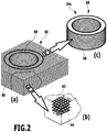
- segments 58 or then a segment group 34a etc. are produced from ceramic composite material by first producing layers 60 of a precursor material.
- the layers 60 comprise fiber scrims (or fiber fabrics or fiber knitted fabrics 62) with, for example, fibers oriented perpendicular to one another.
- 0 ° / 90 ° fiber scrims 62 are indicated.
- Adjacent layers 60 have different fiber orientations. For example, the fiber orientation in relation to adjacent layers is ⁇ 45 °. This is in Figure 2 (b) indicated.
- a fiber scrim 64 adjacent to the fiber scrim 64 is also a 0 ° / 90 ° fiber scrim, with a ⁇ 45 ° alignment.
- the layers 60 can be oriented at any desired angles to one another.
- the individual fibers within a layer 60 can be oriented at any angles to one another.
- Such a stack 66 ( Figure 2 (a) ) is infiltrated with a carbon precursor material and in particular a resin material or the fiber scrims 62 are already provided with such a carbon precursor material (prepreg scrims).
- a precursor segment group 68 is then cut out from such a stack 66 after the carbon precursor material has hardened. The cutting out can take place before a pyrolysis of the stack 66 or after the pyrolysis. If the cutting is carried out before pyrolysis, then the precursor segment group 68 is a resin fiber fabric body (or resin fiber fabric body, resin fiber fabric body, etc.). If the cutting is done after pyrolysis, then the precursor segment group body is a carbon body.
- ceramization takes place by means of the LSI process (Liquid Silicon Infiltration), in which liquid silicon is supplied to the porous carbon body. This liquid silicon reacts with carbon to form silicon carbide.
- a carbide-ceramic C / C-SiC body is then produced if the fibers of the fiber scrim 62, 64 were carbon fibers and in which a precursor polymer plastic matrix was converted into carbon.
- Alternative ceramization processes such as CVI, LPI, etc. usually result in a C-SiC material. In such ceramization processes, the carbon fibers only react marginally with the silicon.
- Shrinkage usually occurs during pyrolysis. It is therefore advantageous if the pyrolysis is carried out on the stack 66 and then the precursor segment group body 68 is produced.
- the first wall device 38 can thus be produced from one piece or several segment groups 34a, 34b, 34c are produced.
- Various precursor segment group bodies can also be produced, which are then joined to one another during ceramization or, for example, also glued.
- the segment groups 34a, 34b, 34c or precursor segment group bodies 68 can also only be axially clamped against one another by means of external bracing if the centering is ensured.
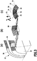
- Figure 3 (a) a section from the combustion chamber 12 is shown.
- Figure 3 (b) a section of the first wall device is shown schematically. Different segments 58 have different fiber orientations (cf. Figure 2 (b) ).
- fibers 70 of high thermal conductivity are arranged in the first wall device 28.
- the Thermal conductivity (integral) is at least 100 W / mK and preferably at least 300 W / mK. For example, it can also reach 1000 W / mK or more.
- the fibers 70 of high thermal conductivity are oriented away from the combustion chamber 14 (or thrust chamber) in a heat transport direction 72.
- the fibers 70 of high thermal conductivity are, for example, C fibers. They are retained as fibers in the first wall device 28.
- the C-fibers are retained during pyrolysis. Oxidation protection for operational use can, if necessary, be achieved by ceramization with carbide former, or by introducing additional oxidic fiber components or matrix components.
- the fibers 70 of high thermal conductivity run from the inside 30 to the outside 32 in a cooling channel 56.
- a corresponding fiber 70 ends with a corresponding fiber end on the inside 30 and with the opposite fiber end in a flow space 74 of the corresponding channel 56.
- the corresponding fiber ends can end directly at the inside 30 or outside 32, or a corresponding coating can also be present there, as will be explained in more detail below.
- Fibers 70 of high thermal conductivity are oriented transversely and, in particular, perpendicular to the axial axis 16. Fibers 70 of high thermal conductivity are in particular oriented radially (that is, parallel to radial direction 52). In particular, most of the fibers 70 of high thermal conductivity are oriented in at least approximately a radial direction.
- the radial direction 52 is a direction in which the distance between the inside 30 and the outside 32 is the smallest.
- Fibers 70 of high thermal conductivity can also be provided which are not oriented in the radial direction.
- fibers 70 of high thermal conductivity in the first wall device 28 are at least 30%, preferably at least 40% and particularly preferably at least 50% and preferably at least 55%, or at least 60%, or at least 65%. In one embodiment, the volume fraction is approximately 70%.
- heat can be dissipated in a targeted manner in the heat transport direction 72 from the inside 38 into the cooling channel device 54. This in turn allows the combustion chamber 12 or thrust chamber to be regeneratively cooled in an effective manner.
- the corresponding wall material in order to prevent overheating of the first wall device 28, the corresponding wall material must have a high temperature resistance and must have a high thermal conductivity.
- a high local temperature gradient usually means that there are high thermal voltages, which in turn leads to material problems (in particular Material fatigue).
- a ceramic composite material has, on the one hand, high temperature resistance and low thermal expansion. The combination of high temperature resistance, high thermal conductivity and low thermal brittleness enables high temperature gradients across the wall profile from the hot gas side to the cooling channel 56. High temperature gradients also enable a certain and necessary heat flow into the first wall device 28 with already lower thermal conductivities and greater wall thicknesses than for example with metallic wall structures.
- fibers 70 of high thermal conductivity to provide defined heat transport paths and thus to increase the integral thermal conductivity, a high cooling efficiency is obtained with great structural integrity.
- the first wall device 28 is designed to be fluid-tight. This can be achieved in a number of ways.
- the first wall device 28 has a fluid-impermeable coating on the outside 82.
- the material of the first wall device 28 it is possible for the material of the first wall device 28 to have closed pores or to be pore-free. If there are pores, they can be closed by an appropriate impregnation. During ceramization, for example, it can also be ensured that the ceramic material is pore-free or has closed pores.
- the first wall device 28 is partially permeable between the combustion chamber 14 (or thrust chamber) and the cooling duct device 54.
- cooling fluid which is in particular fuel such as hydrogen
- a certain proportion of perspiration can take place through the first wall device 28 in certain areas.
- a film of cooling fluid can form on the inside 30 of the first wall device 28 in specific areas.
- Such a film reduces wall friction, for example, and thereby reduces throttling losses.
- an additional cooling effect can also take place via transpiration cooling.
- the inside 30 and the outside 32 can be easily ground and also coated, since the fiber ends end at the inside 30 and the outside 32. This prevents the fibers from splaying out.
- a grinding surface then has a homogeneous roughness. This in turn allows coatings to be applied with good adhesion. For example, sputter layers, plasma coatings, electroplated coatings, etc. can then be produced.
- the exterior 32 is coated with a coating 76, as in FIG Figure 3 (c) indicated, provided.
- the coating 76 is made in particular from a metallic material and extends over the entire outer side 32.
- a fluid-tight design of the first wall device 28 is thereby achieved.
- the coating 76 made of a metallic material of high thermal conductivity such as copper, it is achieved that a homogeneous temperature distribution is formed on the outside 32 of the first wall device 28. This in turn prevents local peak loads on the material of the first wall device 28.
- the inside 30 can be coated with a coating 78 (cf. Figure 3 (c) ) be provided.
- This coating is preferably made from a material with high heat transfer to the first wall device 28.
- it is made of a ceramic material (carbide ceramic or oxide ceramic).
- a ceramic material is silicon carbide, for example.
- the fibers 70 in the first wall device 28 are effectively protected in a matrix, the ceramic composite material.
- the first wall device 28 can be made of a carbide ceramic material, for example.
- it can also be made from an oxide ceramic material.
- the combustion chamber device works as follows: The combustion chamber device 10 is explained in an example in which combustion takes place in the combustion chamber 14. Hydrogen and oxidizer are coupled into combustion chamber 14 via injector device 46. A main flow direction 20 in the combustion chamber 14 is parallel to the axial axis 16 (cf. Figure 4 ). For example, in a combustion chamber area 80 ( Figure 1 ), the flow is subsonic, i.e. there is a subsonic flow. A supersonic flow area 82 is present in the areas 24, 26 of the nozzle device 18.
- Cooling fluid in particular hydrogen
- the cooling fluid absorbs heat, which is provided via the first wall device 28, and is preheated in the process.
- the preheated cooling fluid is then, if it is fuel, injected into the combustion chamber 14 via the injector device 46.
- the cooling fluid is, for example, hydrogen and in particular liquid hydrogen. Heat is effectively dissipated from the inside 30 to the outside 32 of the first wall device 28 via the fibers 70 of high thermal conductivity.
- the direction of flow 84 can also be designed in the opposite direction.
- the preheated fuel is still used to operate turbo pumps by means of enthalpy output before injection at an injector, i.e. fuel that is assigned to a combustion chamber or thrust chamber in the corresponding (regenerative) cooling channel device is, has been heated up, transfers the enthalpy taken up when flowing through a turbine to this before the Fuel is injected into the combustion chamber in an injection head.
- a turbo pump is then operated with the fuel during the expander cycle.
- a flow direction of the cooling fluid can be parallel to the main flow direction of a hot gas flow in the combustion chamber (co-flow) or opposite (counter-flow).
- a first wall device 88 which delimits the combustion chamber 90 in a rotationally symmetrical manner around the axial axis 16 (the same reference numerals are used for the same elements as in the combustion chamber 12).
- the first wall device is made of a ceramic composite material. It has an inner side 92, which delimits the combustion chamber, and an outer side 94. In the area of the outer side 94, cooling channels 96 of the cooling channel device 54 are formed in the first wall device 88. The cooling channels 96 are arranged circumferentially on the outside 94.
- Adjacent cooling channels 96a, 96b are spaced apart from one another in the circumferential direction with a web 98 in between.
- the cooling channels 96 are arranged uniformly distributed around the circumference of the first wall device 88 on the outside 94.
- the cooling channels 96 are integrated into the first wall device 88.
- the first wall device 88 is thus designed in a corresponding meandering shape on the outside 94.
- a coating can be provided on the inside 92 and / or the outside 94.
- the cooling channels 96 are oriented parallel to the axial axis 16.
- a thermal blocking device 100 can be provided. This is arranged around the outside 94 of the first wall device 88.
- the thermal blocking device allows a high heat input into a second wall means surrounding the first wall means 88 prevent. (Such a high heat input can in principle take place via the webs 98.)
- the thermal blocking device 100 is located between an outside of the webs 98 and the second wall device as an outer liner.
- the thermal blocking device 100 is formed, for example, by a tubular element 102 which is pushed over the first wall device 84.
- the thermal barrier device 100 provides a thermal insulation layer. It is made, for example, of a poorly thermally conductive fiber-ceramic material, for example based on aluminum oxide.
- this thermal barrier device has a certain open porosity. This thermal barrier device 100 can then be saturated with “cold” cooling fluid and additionally cooled.
- combustion chamber 86 functions as described above.
- the combustion chamber device according to the invention is, for example, part of a propulsion device of a missile and in particular of a rocket.
Landscapes
- Engineering & Computer Science (AREA)
- Chemical & Material Sciences (AREA)
- Combustion & Propulsion (AREA)
- Mechanical Engineering (AREA)
- General Engineering & Computer Science (AREA)
- Cylinder Crankcases Of Internal Combustion Engines (AREA)
Claims (13)
- Dispositif de chambre de combustion ou dispositif de chambre de poussée, comprenant un premier système de parois (28 ; 88), qui limite avec une face interne (30 ; 92) une chambre de combustion (14 ; 90) ou une chambre de poussée, et un second système de parois (36), qui avec une face interne (38) est tourné vers une face externe (32 ; 94) du premier système de parois (28 ; 88), dans lequel le premier système de parois (28 ; 88) est fabriqué à partir d'un matériau composite céramique, et un système de canalisation de refroidissement (54) pour le refroidissement du premier système de parois (28 ; 88) avec un fluide de refroidissement, qui comprend au moins une canalisation de refroidissement (56 ; 96), qui est disposée ou formée au niveau du premier système de parois (84) et/ou du second système de parois (36) et/ou entre le premier système de parois et le second système de parois, dans lequel des fibres (70) à grande conductibilité thermique sont disposées dans le premier système de parois (28), qui sont disposées écartées de la face interne (30 ; 92) dans la direction du transport thermique (72) et qui présentent une conductibilité thermique d'au moins 100 W/mK, dans lequel des extrémités de fibre des fibres (70) à grande conductibilité thermique se terminent au niveau ou à proximité de la face interne (30 ; 92) du premier système de parois (28 ; 88), dans lequel les fibres (70) à grande conductibilité thermique sont posées de la face interne (30 ; 92) du premier système de parois à l'au moins une canalisation (56 ; 96),
caractérisé en ce que
des extrémités de fibre des fibres (70) à grande conductibilité thermique se terminent au niveau d'un espace d'écoulement (74) ou à proximité d'un espace d'écoulement (74) de l'au moins une canalisation (56 ; 96) . - Dispositif de chambre de combustion ou dispositif de chambre de poussée selon l'une quelconque des revendications précédentes, caractérisé en ce que l'au moins une canalisation (56 ; 96) comprend une direction d'étendue qui est au moins approximativement parallèle à un axe axial (16) du premier système de parois (28 ; 88).
- Dispositif de chambre de combustion ou dispositif de chambre de poussée selon l'une quelconque des revendications précédentes, caractérisé en ce que les fibres (70) à grande conductibilité thermique sont orientées au moins approximativement en direction radiale (52) par rapport à un axe axial (16) du premier système de parois (28 ; 88).
- Dispositif de chambre de combustion ou dispositif de chambre de poussée selon l'une quelconque des revendications précédentes, caractérisé en ce que le premier système de parois (28 ; 88) est formé en tant que doublure interne et/ou en ce que le second système de parois (36) entoure le premier système de parois (28 ; 88) et/ou en ce que le second système de parois (88) est formé en tant que doublure externe.
- Dispositif de chambre de combustion ou dispositif de chambre de poussée selon l'une quelconque des revendications précédentes, caractérisé en ce que, au niveau du premier système de parois (88) dans la zone de la face externe (94) sont formées une pluralité de canalisations de refroidissement (96), qui sont écartées les unes des autres dans une direction circonférentielle et, en particulier, en ce que les canalisations de refroidissement (96) sont disposées réparties uniformément dans la direction circonférentielle.
- Dispositif de chambre de combustion ou dispositif de chambre de poussée selon l'une quelconque des revendications précédentes, caractérisé en ce qu'un système d'isolation thermique (100) est disposé entre le premier système de parois (88) et le second système de parois et, en particulier, en ce que le système d'isolation thermique (100) est formé par au moins un élément tubulaire (102).
- Dispositif de chambre de combustion ou dispositif de chambre de poussée selon l'une quelconque des revendications précédentes, caractérisé en ce que les fibres (70) à grande conductibilité thermique comprennent des fibres en carbone.
- Dispositif de chambre de combustion ou dispositif de chambre de poussée selon l'une quelconque des revendications précédentes, caractérisé en ce que le premier système de parois (28 ; 88) comprend une pluralité de segments (58) disposés axialement les uns derrière les autres et, en particulier, en ce que des segments voisins (58) présentent des orientations de fibre différentes ou identiques d'une matrice de renforcement de fibres, et en particulier, en ce que des segments (58) ou des groupes de segments (34a, 34b, 34c) reposent axialement tendus dans le second système de parois (36).
- Dispositif de chambre de combustion ou dispositif de chambre de poussée selon l'une quelconque des revendications précédentes, caractérisé en ce que le premier système de parois (28 ; 88) est formé au moins en partie imperméable aux fluides et, en particulier, en ce que le premier système de parois (28 ; 88) comprend au niveau de la face externe (32) un revêtement imperméable aux fluides (76) et, en particulier, en ce que le matériau du premier système de parois (28 ; 88) comprend des pores fermés ou est exempt de pores.
- Dispositif de chambre de combustion ou dispositif de chambre de poussée selon l'une quelconque des revendications précédentes, caractérisé en ce qu'une part volumique des fibres (70) à grande conductibilité thermique dans le premier système de parois représente au moins 30 %, en particulier au moins 40 % et en particulier au moins 50 %, en particulier au moins 60 % et en particulier au moins 70 %.
- Dispositif de chambre de combustion ou dispositif de chambre de poussée selon l'une quelconque des revendications précédentes, caractérisé en ce que la chambre de combustion (14) ou la chambre de poussée est formée avec une symétrie de rotation autour d'un axe axial (16).
- Dispositif de chambre de combustion ou dispositif de chambre de poussée selon l'une quelconque des revendications précédentes, caractérisé en ce que le premier système de parois (28 ; 88) est fabriqué à partir d'une matière céramique au carbure ou céramique à oxyde ou d'un matériau en carbone à grande conductibilité thermique et/ou en ce que le second système de parois (36) est fabriqué en un matériau composite en fibres.
- Dispositif de chambre de combustion ou dispositif de chambre de poussée selon l'une quelconque des revendications précédentes, caractérisé en ce que le premier système de parois (28 ; 88) est revêtu au niveau de la face interne (30 ; 92) et/ou en ce que le premier système de parois (28 ; 88) est revêtu au niveau de la face externe (32).
Applications Claiming Priority (1)
| Application Number | Priority Date | Filing Date | Title |
|---|---|---|---|
| DE102011052413A DE102011052413A1 (de) | 2011-08-04 | 2011-08-04 | Brennkammervorrichtung oder Schubkammervorrichtung |
Publications (3)
| Publication Number | Publication Date |
|---|---|
| EP2554904A2 EP2554904A2 (fr) | 2013-02-06 |
| EP2554904A3 EP2554904A3 (fr) | 2017-12-20 |
| EP2554904B1 true EP2554904B1 (fr) | 2020-09-23 |
Family
ID=47002558
Family Applications (1)
| Application Number | Title | Priority Date | Filing Date |
|---|---|---|---|
| EP12179345.9A Active EP2554904B1 (fr) | 2011-08-04 | 2012-08-06 | Dispositif de chambre de combustion ou dispositif de chambre de poussée |
Country Status (2)
| Country | Link |
|---|---|
| EP (1) | EP2554904B1 (fr) |
| DE (1) | DE102011052413A1 (fr) |
Families Citing this family (1)
| Publication number | Priority date | Publication date | Assignee | Title |
|---|---|---|---|---|
| CN114459057B (zh) * | 2022-01-18 | 2023-03-24 | 中国航发四川燃气涡轮研究院 | 陶瓷基火焰筒连接结构及燃气涡轮发动机燃烧室 |
Citations (1)
| Publication number | Priority date | Publication date | Assignee | Title |
|---|---|---|---|---|
| DE102008020198A1 (de) * | 2008-04-15 | 2009-10-22 | Astrium Gmbh | Düsenerweiterung für ein Triebwerk und Verfahren zur Herstellung und Kühlung einer Düsenerweiterung |
Family Cites Families (6)
| Publication number | Priority date | Publication date | Assignee | Title |
|---|---|---|---|---|
| US5780157A (en) * | 1994-06-06 | 1998-07-14 | Ultramet | Composite structure |
| DE19730674A1 (de) * | 1997-07-17 | 1999-01-21 | Deutsch Zentr Luft & Raumfahrt | Brennkammer und Verfahren zur Herstellung einer Brennkammer |
| US6783824B2 (en) * | 2001-01-25 | 2004-08-31 | Hyper-Therm High-Temperature Composites, Inc. | Actively-cooled fiber-reinforced ceramic matrix composite rocket propulsion thrust chamber and method of producing the same |
| DE102005036137A1 (de) | 2005-07-26 | 2007-02-01 | Deutsches Zentrum für Luft- und Raumfahrt e.V. | Brennkammer und Verfahren zur Herstellung einer Brennkammer |
| DE102005059502A1 (de) * | 2005-12-06 | 2007-06-14 | Deutsches Zentrum für Luft- und Raumfahrt e.V. | Heißkammer |
| DE102009028470B4 (de) * | 2009-08-12 | 2011-07-28 | Deutsches Zentrum für Luft- und Raumfahrt e.V., 51147 | Absorbervorrichtung |
-
2011
- 2011-08-04 DE DE102011052413A patent/DE102011052413A1/de not_active Withdrawn
-
2012
- 2012-08-06 EP EP12179345.9A patent/EP2554904B1/fr active Active
Patent Citations (1)
| Publication number | Priority date | Publication date | Assignee | Title |
|---|---|---|---|---|
| DE102008020198A1 (de) * | 2008-04-15 | 2009-10-22 | Astrium Gmbh | Düsenerweiterung für ein Triebwerk und Verfahren zur Herstellung und Kühlung einer Düsenerweiterung |
Also Published As
| Publication number | Publication date |
|---|---|
| DE102011052413A1 (de) | 2013-02-07 |
| EP2554904A2 (fr) | 2013-02-06 |
| EP2554904A3 (fr) | 2017-12-20 |
Similar Documents
| Publication | Publication Date | Title |
|---|---|---|
| EP0927299B1 (fr) | Chambre de combustion et procede permettant de realiser une chambre de combustion | |
| DE60224412T2 (de) | Keramikmatrix-verbundstruktur mit integriertem kühlkanal und herstellungsverfahren | |
| DE69916240T2 (de) | Wärmetauscher aus verbundwerkstoff und dessen herstellungsverfahren | |
| DE60224691T2 (de) | Keramisches hybridmaterial aus keramischen isolier- und konstruktionsschichten | |
| DE102011050757B4 (de) | Brennkammerflammrohrkühlsystem | |
| EP0913373B1 (fr) | Matériau composite céramique renforcé par des fibres de carbone | |
| DE29714742U1 (de) | Hitzeschildkomponente mit Kühlfluidrückführung und Hitzeschildanordnung für eine heißgasführende Komponente | |
| WO1999027304A1 (fr) | Chambre de combustion et procede de refroidissement par vapeur d'une chambre de combustion | |
| WO2007128837A1 (fr) | Corps soumis à l'action d'un fluide et résistant à la pression | |
| DE69622226T2 (de) | Hybride Verbundwerkstücke und Geschossbauteile und ihre Herstellung | |
| EP2554904B1 (fr) | Dispositif de chambre de combustion ou dispositif de chambre de poussée | |
| EP1748253B1 (fr) | Chambre de combustion et procédé de fabrication d'une chambre de combustion | |
| DE102004029029B4 (de) | Einspritzkopf | |
| EP1939529A1 (fr) | Revêtement de chambre de combustion CMC à structure à double couche | |
| DE102010043336B4 (de) | Brennkammervorrichtung | |
| EP2227629B1 (fr) | Dispositif de chambre de combustion | |
| DE69002215T2 (de) | Raketenbrennkammer. | |
| Cavalier et al. | Composites in aerospace industry | |
| DE19937812A1 (de) | Bauelement mit einem bei erhöhter Temperatur belastbaren Teil aus Verbundwerkstoff mit Fluidumwälzkühlung | |
| DE102008020198B4 (de) | Düsenerweiterung für ein Triebwerk und Verfahren zur Herstellung und Kühlung einer Düsenerweiterung | |
| DE10230231B4 (de) | Mehrschichtiger Verbundwerkstoff | |
| DE102014100345B4 (de) | Verfahren zur Herstellung einer Schubkammervorrichtung, Schubkammervorrichtung und Raketentriebwerk | |
| WO2004085828A2 (fr) | Soupape a injection directe dans une culasse | |
| DE102023002467A1 (de) | Abgaskrümmer, Zylinderkopf und Verfahren zur Auslegung von Abgaskrümmern | |
| DE102017129321B4 (de) | Brennkammervorrichtung, Fahrzeug |
Legal Events
| Date | Code | Title | Description |
|---|---|---|---|
| PUAI | Public reference made under article 153(3) epc to a published international application that has entered the european phase |
Free format text: ORIGINAL CODE: 0009012 |
|
| AK | Designated contracting states |
Kind code of ref document: A2 Designated state(s): AL AT BE BG CH CY CZ DE DK EE ES FI FR GB GR HR HU IE IS IT LI LT LU LV MC MK MT NL NO PL PT RO RS SE SI SK SM TR |
|
| AX | Request for extension of the european patent |
Extension state: BA ME |
|
| PUAL | Search report despatched |
Free format text: ORIGINAL CODE: 0009013 |
|
| AK | Designated contracting states |
Kind code of ref document: A3 Designated state(s): AL AT BE BG CH CY CZ DE DK EE ES FI FR GB GR HR HU IE IS IT LI LT LU LV MC MK MT NL NO PL PT RO RS SE SI SK SM TR |
|
| AX | Request for extension of the european patent |
Extension state: BA ME |
|
| RIC1 | Information provided on ipc code assigned before grant |
Ipc: F23M 5/08 20060101ALI20171115BHEP Ipc: F23R 3/00 20060101AFI20171115BHEP |
|
| STAA | Information on the status of an ep patent application or granted ep patent |
Free format text: STATUS: REQUEST FOR EXAMINATION WAS MADE |
|
| 17P | Request for examination filed |
Effective date: 20180618 |
|
| RBV | Designated contracting states (corrected) |
Designated state(s): AL AT BE BG CH CY CZ DE DK EE ES FI FR GB GR HR HU IE IS IT LI LT LU LV MC MK MT NL NO PL PT RO RS SE SI SK SM TR |
|
| STAA | Information on the status of an ep patent application or granted ep patent |
Free format text: STATUS: EXAMINATION IS IN PROGRESS |
|
| 17Q | First examination report despatched |
Effective date: 20191008 |
|
| GRAP | Despatch of communication of intention to grant a patent |
Free format text: ORIGINAL CODE: EPIDOSNIGR1 |
|
| STAA | Information on the status of an ep patent application or granted ep patent |
Free format text: STATUS: GRANT OF PATENT IS INTENDED |
|
| INTG | Intention to grant announced |
Effective date: 20200420 |
|
| GRAS | Grant fee paid |
Free format text: ORIGINAL CODE: EPIDOSNIGR3 |
|
| GRAA | (expected) grant |
Free format text: ORIGINAL CODE: 0009210 |
|
| STAA | Information on the status of an ep patent application or granted ep patent |
Free format text: STATUS: THE PATENT HAS BEEN GRANTED |
|
| AK | Designated contracting states |
Kind code of ref document: B1 Designated state(s): AL AT BE BG CH CY CZ DE DK EE ES FI FR GB GR HR HU IE IS IT LI LT LU LV MC MK MT NL NO PL PT RO RS SE SI SK SM TR |
|
| REG | Reference to a national code |
Ref country code: GB Ref legal event code: FG4D Free format text: NOT ENGLISH |
|
| REG | Reference to a national code |
Ref country code: CH Ref legal event code: EP |
|
| REG | Reference to a national code |
Ref country code: IE Ref legal event code: FG4D Free format text: LANGUAGE OF EP DOCUMENT: GERMAN |
|
| REG | Reference to a national code |
Ref country code: DE Ref legal event code: R096 Ref document number: 502012016364 Country of ref document: DE Ref country code: AT Ref legal event code: REF Ref document number: 1316764 Country of ref document: AT Kind code of ref document: T Effective date: 20201015 |
|
| PG25 | Lapsed in a contracting state [announced via postgrant information from national office to epo] |
Ref country code: GR Free format text: LAPSE BECAUSE OF FAILURE TO SUBMIT A TRANSLATION OF THE DESCRIPTION OR TO PAY THE FEE WITHIN THE PRESCRIBED TIME-LIMIT Effective date: 20201224 Ref country code: NO Free format text: LAPSE BECAUSE OF FAILURE TO SUBMIT A TRANSLATION OF THE DESCRIPTION OR TO PAY THE FEE WITHIN THE PRESCRIBED TIME-LIMIT Effective date: 20201223 Ref country code: SE Free format text: LAPSE BECAUSE OF FAILURE TO SUBMIT A TRANSLATION OF THE DESCRIPTION OR TO PAY THE FEE WITHIN THE PRESCRIBED TIME-LIMIT Effective date: 20200923 Ref country code: FI Free format text: LAPSE BECAUSE OF FAILURE TO SUBMIT A TRANSLATION OF THE DESCRIPTION OR TO PAY THE FEE WITHIN THE PRESCRIBED TIME-LIMIT Effective date: 20200923 Ref country code: HR Free format text: LAPSE BECAUSE OF FAILURE TO SUBMIT A TRANSLATION OF THE DESCRIPTION OR TO PAY THE FEE WITHIN THE PRESCRIBED TIME-LIMIT Effective date: 20200923 Ref country code: BG Free format text: LAPSE BECAUSE OF FAILURE TO SUBMIT A TRANSLATION OF THE DESCRIPTION OR TO PAY THE FEE WITHIN THE PRESCRIBED TIME-LIMIT Effective date: 20201223 |
|
| PG25 | Lapsed in a contracting state [announced via postgrant information from national office to epo] |
Ref country code: RS Free format text: LAPSE BECAUSE OF FAILURE TO SUBMIT A TRANSLATION OF THE DESCRIPTION OR TO PAY THE FEE WITHIN THE PRESCRIBED TIME-LIMIT Effective date: 20200923 Ref country code: LV Free format text: LAPSE BECAUSE OF FAILURE TO SUBMIT A TRANSLATION OF THE DESCRIPTION OR TO PAY THE FEE WITHIN THE PRESCRIBED TIME-LIMIT Effective date: 20200923 |
|
| REG | Reference to a national code |
Ref country code: NL Ref legal event code: MP Effective date: 20200923 |
|
| REG | Reference to a national code |
Ref country code: LT Ref legal event code: MG4D |
|
| PG25 | Lapsed in a contracting state [announced via postgrant information from national office to epo] |
Ref country code: PT Free format text: LAPSE BECAUSE OF FAILURE TO SUBMIT A TRANSLATION OF THE DESCRIPTION OR TO PAY THE FEE WITHIN THE PRESCRIBED TIME-LIMIT Effective date: 20210125 Ref country code: LT Free format text: LAPSE BECAUSE OF FAILURE TO SUBMIT A TRANSLATION OF THE DESCRIPTION OR TO PAY THE FEE WITHIN THE PRESCRIBED TIME-LIMIT Effective date: 20200923 Ref country code: NL Free format text: LAPSE BECAUSE OF FAILURE TO SUBMIT A TRANSLATION OF THE DESCRIPTION OR TO PAY THE FEE WITHIN THE PRESCRIBED TIME-LIMIT Effective date: 20200923 Ref country code: SM Free format text: LAPSE BECAUSE OF FAILURE TO SUBMIT A TRANSLATION OF THE DESCRIPTION OR TO PAY THE FEE WITHIN THE PRESCRIBED TIME-LIMIT Effective date: 20200923 Ref country code: RO Free format text: LAPSE BECAUSE OF FAILURE TO SUBMIT A TRANSLATION OF THE DESCRIPTION OR TO PAY THE FEE WITHIN THE PRESCRIBED TIME-LIMIT Effective date: 20200923 Ref country code: EE Free format text: LAPSE BECAUSE OF FAILURE TO SUBMIT A TRANSLATION OF THE DESCRIPTION OR TO PAY THE FEE WITHIN THE PRESCRIBED TIME-LIMIT Effective date: 20200923 Ref country code: CZ Free format text: LAPSE BECAUSE OF FAILURE TO SUBMIT A TRANSLATION OF THE DESCRIPTION OR TO PAY THE FEE WITHIN THE PRESCRIBED TIME-LIMIT Effective date: 20200923 |
|
| PG25 | Lapsed in a contracting state [announced via postgrant information from national office to epo] |
Ref country code: AL Free format text: LAPSE BECAUSE OF FAILURE TO SUBMIT A TRANSLATION OF THE DESCRIPTION OR TO PAY THE FEE WITHIN THE PRESCRIBED TIME-LIMIT Effective date: 20200923 Ref country code: ES Free format text: LAPSE BECAUSE OF FAILURE TO SUBMIT A TRANSLATION OF THE DESCRIPTION OR TO PAY THE FEE WITHIN THE PRESCRIBED TIME-LIMIT Effective date: 20200923 Ref country code: IS Free format text: LAPSE BECAUSE OF FAILURE TO SUBMIT A TRANSLATION OF THE DESCRIPTION OR TO PAY THE FEE WITHIN THE PRESCRIBED TIME-LIMIT Effective date: 20210123 Ref country code: PL Free format text: LAPSE BECAUSE OF FAILURE TO SUBMIT A TRANSLATION OF THE DESCRIPTION OR TO PAY THE FEE WITHIN THE PRESCRIBED TIME-LIMIT Effective date: 20200923 |
|
| REG | Reference to a national code |
Ref country code: DE Ref legal event code: R097 Ref document number: 502012016364 Country of ref document: DE |
|
| PG25 | Lapsed in a contracting state [announced via postgrant information from national office to epo] |
Ref country code: SK Free format text: LAPSE BECAUSE OF FAILURE TO SUBMIT A TRANSLATION OF THE DESCRIPTION OR TO PAY THE FEE WITHIN THE PRESCRIBED TIME-LIMIT Effective date: 20200923 |
|
| PLBE | No opposition filed within time limit |
Free format text: ORIGINAL CODE: 0009261 |
|
| STAA | Information on the status of an ep patent application or granted ep patent |
Free format text: STATUS: NO OPPOSITION FILED WITHIN TIME LIMIT |
|
| PG25 | Lapsed in a contracting state [announced via postgrant information from national office to epo] |
Ref country code: DK Free format text: LAPSE BECAUSE OF FAILURE TO SUBMIT A TRANSLATION OF THE DESCRIPTION OR TO PAY THE FEE WITHIN THE PRESCRIBED TIME-LIMIT Effective date: 20200923 Ref country code: SI Free format text: LAPSE BECAUSE OF FAILURE TO SUBMIT A TRANSLATION OF THE DESCRIPTION OR TO PAY THE FEE WITHIN THE PRESCRIBED TIME-LIMIT Effective date: 20200923 |
|
| 26N | No opposition filed |
Effective date: 20210624 |
|
| PG25 | Lapsed in a contracting state [announced via postgrant information from national office to epo] |
Ref country code: IT Free format text: LAPSE BECAUSE OF FAILURE TO SUBMIT A TRANSLATION OF THE DESCRIPTION OR TO PAY THE FEE WITHIN THE PRESCRIBED TIME-LIMIT Effective date: 20200923 |
|
| REG | Reference to a national code |
Ref country code: CH Ref legal event code: PL |
|
| PG25 | Lapsed in a contracting state [announced via postgrant information from national office to epo] |
Ref country code: MC Free format text: LAPSE BECAUSE OF FAILURE TO SUBMIT A TRANSLATION OF THE DESCRIPTION OR TO PAY THE FEE WITHIN THE PRESCRIBED TIME-LIMIT Effective date: 20200923 |
|
| REG | Reference to a national code |
Ref country code: BE Ref legal event code: MM Effective date: 20210831 |
|
| GBPC | Gb: european patent ceased through non-payment of renewal fee |
Effective date: 20210806 |
|
| PG25 | Lapsed in a contracting state [announced via postgrant information from national office to epo] |
Ref country code: LI Free format text: LAPSE BECAUSE OF NON-PAYMENT OF DUE FEES Effective date: 20210831 Ref country code: CH Free format text: LAPSE BECAUSE OF NON-PAYMENT OF DUE FEES Effective date: 20210831 |
|
| PG25 | Lapsed in a contracting state [announced via postgrant information from national office to epo] |
Ref country code: LU Free format text: LAPSE BECAUSE OF NON-PAYMENT OF DUE FEES Effective date: 20210806 |
|
| PG25 | Lapsed in a contracting state [announced via postgrant information from national office to epo] |
Ref country code: IE Free format text: LAPSE BECAUSE OF NON-PAYMENT OF DUE FEES Effective date: 20210806 Ref country code: GB Free format text: LAPSE BECAUSE OF NON-PAYMENT OF DUE FEES Effective date: 20210806 Ref country code: FR Free format text: LAPSE BECAUSE OF NON-PAYMENT OF DUE FEES Effective date: 20210831 Ref country code: BE Free format text: LAPSE BECAUSE OF NON-PAYMENT OF DUE FEES Effective date: 20210831 |
|
| REG | Reference to a national code |
Ref country code: AT Ref legal event code: MM01 Ref document number: 1316764 Country of ref document: AT Kind code of ref document: T Effective date: 20210806 |
|
| PG25 | Lapsed in a contracting state [announced via postgrant information from national office to epo] |
Ref country code: AT Free format text: LAPSE BECAUSE OF NON-PAYMENT OF DUE FEES Effective date: 20210806 |
|
| PG25 | Lapsed in a contracting state [announced via postgrant information from national office to epo] |
Ref country code: HU Free format text: LAPSE BECAUSE OF FAILURE TO SUBMIT A TRANSLATION OF THE DESCRIPTION OR TO PAY THE FEE WITHIN THE PRESCRIBED TIME-LIMIT; INVALID AB INITIO Effective date: 20120806 Ref country code: CY Free format text: LAPSE BECAUSE OF FAILURE TO SUBMIT A TRANSLATION OF THE DESCRIPTION OR TO PAY THE FEE WITHIN THE PRESCRIBED TIME-LIMIT Effective date: 20200923 |
|
| PG25 | Lapsed in a contracting state [announced via postgrant information from national office to epo] |
Ref country code: MK Free format text: LAPSE BECAUSE OF FAILURE TO SUBMIT A TRANSLATION OF THE DESCRIPTION OR TO PAY THE FEE WITHIN THE PRESCRIBED TIME-LIMIT Effective date: 20200923 |
|
| PG25 | Lapsed in a contracting state [announced via postgrant information from national office to epo] |
Ref country code: MT Free format text: LAPSE BECAUSE OF FAILURE TO SUBMIT A TRANSLATION OF THE DESCRIPTION OR TO PAY THE FEE WITHIN THE PRESCRIBED TIME-LIMIT Effective date: 20200923 |
|
| PGFP | Annual fee paid to national office [announced via postgrant information from national office to epo] |
Ref country code: DE Payment date: 20250709 Year of fee payment: 14 |
|
| PG25 | Lapsed in a contracting state [announced via postgrant information from national office to epo] |
Ref country code: TR Free format text: LAPSE BECAUSE OF FAILURE TO SUBMIT A TRANSLATION OF THE DESCRIPTION OR TO PAY THE FEE WITHIN THE PRESCRIBED TIME-LIMIT Effective date: 20200923 |