EP2554931A1 - Support et équipement de mouvement - Google Patents
Support et équipement de mouvement Download PDFInfo
- Publication number
- EP2554931A1 EP2554931A1 EP11176309A EP11176309A EP2554931A1 EP 2554931 A1 EP2554931 A1 EP 2554931A1 EP 11176309 A EP11176309 A EP 11176309A EP 11176309 A EP11176309 A EP 11176309A EP 2554931 A1 EP2554931 A1 EP 2554931A1
- Authority
- EP
- European Patent Office
- Prior art keywords
- support
- movement equipment
- rotation
- pin
- opening
- Prior art date
- Legal status (The legal status is an assumption and is not a legal conclusion. Google has not performed a legal analysis and makes no representation as to the accuracy of the status listed.)
- Withdrawn
Links
Images


Classifications
-
- F—MECHANICAL ENGINEERING; LIGHTING; HEATING; WEAPONS; BLASTING
- F25—REFRIGERATION OR COOLING; COMBINED HEATING AND REFRIGERATION SYSTEMS; HEAT PUMP SYSTEMS; MANUFACTURE OR STORAGE OF ICE; LIQUEFACTION SOLIDIFICATION OF GASES
- F25D—REFRIGERATORS; COLD ROOMS; ICE-BOXES; COOLING OR FREEZING APPARATUS NOT OTHERWISE PROVIDED FOR
- F25D23/00—General constructional features
-
- B—PERFORMING OPERATIONS; TRANSPORTING
- B60—VEHICLES IN GENERAL
- B60B—VEHICLE WHEELS; CASTORS; AXLES FOR WHEELS OR CASTORS; INCREASING WHEEL ADHESION
- B60B33/00—Castors in general ; Anti-clogging castors
-
- B—PERFORMING OPERATIONS; TRANSPORTING
- B60—VEHICLES IN GENERAL
- B60B—VEHICLE WHEELS; CASTORS; AXLES FOR WHEELS OR CASTORS; INCREASING WHEEL ADHESION
- B60B2200/00—Type of product being used or applied
- B60B2200/40—Articles of daily use
- B60B2200/49—Domestic appliances, e.g. vacuum cleaners
-
- F—MECHANICAL ENGINEERING; LIGHTING; HEATING; WEAPONS; BLASTING
- F25—REFRIGERATION OR COOLING; COMBINED HEATING AND REFRIGERATION SYSTEMS; HEAT PUMP SYSTEMS; MANUFACTURE OR STORAGE OF ICE; LIQUEFACTION SOLIDIFICATION OF GASES
- F25D—REFRIGERATORS; COLD ROOMS; ICE-BOXES; COOLING OR FREEZING APPARATUS NOT OTHERWISE PROVIDED FOR
- F25D2400/00—General features of, or devices for refrigerators, cold rooms, ice-boxes, or for cooling or freezing apparatus not covered by any other subclass
- F25D2400/38—Refrigerating devices characterised by wheels
Definitions
- the present disclosure generally refers to the field of support and movement devices adapted to be placed behind or under apparatuses or electrical household appliances, especially those of high dimensions and weight, like e.g. a refrigerator or an oven, in order to foster a displacement, or of devices referred to as "roller beds", of idle-type, used for instance in so-called gravity apparatuses.
- the present disclosure refers to a support and movement equipment for supporting a load, and allowing a facilitated displacement or movement of the load itself.
- a known support and movement equipment generally comprises a support plate provided with wheels or rollers, mounted idle.
- the support plate is provided, on one of its faces, with pairs of walls facing each other, between which the wheel or roller is located and which also act as support for the wheel.
- each wheel is provided with a rotation pin, which is axially inserted, i.e. along the length of the pin, into respective round holes obtained in the above-mentioned walls.
- the support plate is provided with retainers, located close to the respective walls and adapted to interfere with the ends of the pin to prevent the pin from going out of the respective round hole of each wall.
- retainers are sheet metal parts cut out from the support plate and raised toward each of the walls at the height of the pin.
- a drawback lies in the fact that the assembling of the wheel-pin set between the walls is complex. Moreover, the manufacturing of the retainers lengthens the machining times of the support and movement equipment.
- an operator in order to manufacture the retainers, an operator, after having placed the wheel between the two walls and inserted the pin into the holes, has to cut out parts of the support plate and raise/bend the cut-out parts so that, in a raised position, such parts may interfere with the pin.
- the present disclosure is based on the technical problem of providing a support and movement equipment allowing to overcome the drawbacks mentioned above with reference to the known art and/or to attain further advantages and/or to have further features.
- the support and movement equipment includes at least one rotation seat adapted to receive the rotation pin, i.e. a corresponding portion of the pin.
- the rotation seat is open on an edge of a respective wall by means of an opening. It follows that the rotation seat is open toward the edge by means of the above-mentioned opening.
- the set formed by the rotation seat and the opening defines a sort of notch or recess between two wall portions of each wall.
- the insertion zone or opening is the proximal or initial zone of the notch or recess, whereas the rotation seat is the end or final zone of the notch or recess.
- a notch may be facing toward a floor for supporting the support and movement equipment so that the wheel/roller be mainly exposed downward, e.g. during use in an undercarriage mode of the support and movement equipment.
- Such a notch may be facing on the opposite side with respect to a floor, therefore upward, so that the wheel/roller be mainly exposed upward and foster the movement of the load there above, e.g. during use of the support and movement equipment in roller bed mode.
- upward position or “upward” is not to be construed as limitative terms within the scope of the present disclosure.
- the edge may be a wall edge which is opposite with respect to the plate (therefore the wheel is inserted from the side opposite to the plate), or the edge may be a wall edge that therefore is facing toward, or is adjacent to the plate (therefore the wheel is inserted from the side of the plate).
- the insertion of the pin through the opening occurs along a direction which is substantially orthogonal to the axis of rotation of the pin.
- the support and movement equipment includes, retaining elements, also called holding elements, associated to the opening, which are adapted to prevent an accidental coming out, e.g., by gravity, of the rotation pin from the rotation seat through the opening.
- the support and movement equipment 1, 10, 110, 1010 may be used as an undercarriage, and therefore be moved along with a load for transport of the load itself, or as a so-called roller bed, and therefore remain stationary in a place and allow displacement of a load which is displaced by gravity thereon.
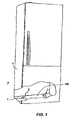
- the support and movement equipment 1, 10, 110, 1010 may be shaped like a crossbar for electrical household appliance, denoted by reference number 100 in Figure 1 , which can be placed below a refrigerator F, or a similar apparatus, for supporting the refrigerator F during a transport. More specifically, the support and movement equipment 1, 10, 110, 1010 may be placed below the compressor (not illustrated) of the refrigerator.
- the support and movement equipment 1, 10, 110, 1010 is a so-called roller bed of a gravity scaffold, or of a similar gravity conveyor, or of another apparatus, utilized for transport of a load thereabove.
- the support and movement equipment 1, 10, 110, 1010 is part of a gravity apparatus, i.e. of an apparatus including slightly tilted planes that, by means of wheel or roller sliding tracks, formed by one or more of said support equipments 1, 10, 110, allow a load unit sliding without any automation, by exploiting the sole force of gravity.
- the support and movement equipment 1, 10, 110, 1010 includes a support plate 2, onto which a load is intended to be placed, and at least one wheel, or roller, 3 provided with a rotation pin 31. It may be observed that the support and movement equipment 1, 10, 110, 1010 is only partially illustrated in Figures 2-17 , in relation to the zone of rotation of a wheel or roller 3, but it is to be understood that the support and movement equipment 1, 10, 110, 1010 may comprise one or more, i.e., a plurality of, wheels 3, associated to the support plate 2.
- the support equipments 1, 10, 110, 1010 are embodiments according to the present disclosure, which, though different from each other, share the following features.
- the support plate 2 includes two sheet metal portions or walls 20, facing the one to the other and projecting from the support plate 2.
- the walls 20 are in a spaced apart relationship and define between them an intermediate housing A.
- the wheel 3 is arranged in the housing A between the walls 20.
- the support plate 2 is a metal sheet.
- the walls 20 are elements which form a single piece with the support plate 2, and are obtained by cutting out and bending/raising the metal sheet portions over the surface of the support plate 2 to define bends T, and so as to form a cavity or hole 22 in the support plate 2. More specifically, the walls 20 form an angle of about 90° with respect to the support plate 2.
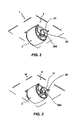
- the support and movement equipment 1, 10, 110, 1010 includes at least one rotation seat 204, 114 adapted to receive the rotation pin 31, i.e. a corresponding portion of the pin 31.
- the wheel 3 is housed idle into the respective rotation seat 114, 204.
- the rotation seat 204, 114 is open on an edge 211, 1211 of a respective wall 20 by means of an opening 203. It follows that the rotation seat 204, 114 is open toward the edge 211, 1211 by means of the above-mentioned opening 203.
- the group formed by the rotation seat 204, 114 and the opening 203 defines a sort of notch or recess between two wall portions 201 of each wall 20.
- the insertion zone 203 is the proximal or initial zone of the notch or recess, whereas the rotation seat 204, 114 is the end or final zone of the notch or recess.
- a notch may be facing toward a floor P for supporting the support and movement equipment 1, 10, 110, 1010, so that the wheel/roller 3 be mainly exposed downward, e.g. during use of the support and movement equipment 1, 10, 110, 1010 in the undercarriage mode.
- Such a notch may be facing the opposite side with respect to a floor P, therefore upward, so that the wheel/roller 3 be mainly exposed upward and foster movement of the load thereabove, e.g. during a use of the support and movement equipment 1, 10, 110, 1010 in the roller bed mode.
- the edge 211 is an edge of the wall 20 which is opposite to the bending zone T, i.e., opposite to the plate 2 (therefore the wheel 3 is inserted from the side opposite to the plate 2)
- the edge 1211 is an edge of the wall 20 that coincides with the bending zone T and therefore faces toward or is adjacent to the plate 2 (therefore the wheel 3 is inserted from the side of the plate 2).
- the insertion zone or opening 203 is on the opposite or distal side with respect to the plate 2, whereas in the embodiment of Figures 13-17 the insertion zone or opening 203 is on the side of the plate 2, or proximal to the plate 2.
- the rotation seat 204, 114 has an axis of rotation R extending in a direction substantially orthogonal to a direction of loading on the support plate 2.
- the opening 203 allows an insertion of the rotation pin 31 into the rotation seat 204, 114, starting from the peripheral edge 211, 1211.
- the opening 203 connects the rotation seat 204, 114 to an external zone.
- An insertion path of the rotation pin 31 which crosses the insertion zone 203 and the rotation seat 204, 114 is defined by a broken line L in the figures.
- the insertion path L is orthogonal to the axis of rotation R.
- the support and movement equipment 1, 10, 110, 1010 includes, associated to the opening 203, retaining elements 300, also referred to as holding elements, which are adapted to prevent an accidental coming out, e.g. by gravity, of the rotation pin 31 from the rotation seat 204, 114 through the opening 203.
- the retaining elements 300 are such that, when the pin is housed into the rotation seat 204, 114 during a standard use of the support and movement equipment 1, 10, 110, 1010, both in roller bed mode and in undercarriage mode, no risk is run of an accidental detaching or coming out of the pin 31 from the rotation seat 204, 114, with a detaching of the wheel 3 from the support plate 2.
- rotation pin 31 may come out from the rotation seat by forcing, or generally by a violation of the retaining elements 300.
- Each of the retaining elements 300 is a part 301 of one of the above-mentioned wall portions 201, i.e. the retaining elements 300 are formed by parts or appendages of the above-mentioned wall portions 201.
- Each one part 301 of said wall portions 201 is projecting toward the other one, and is arranged in the region of the opening 203.
- each part 301 of the wall portions 201 is lobe-shaped and has a rounded contour.
- lobes 301 or parts are coplanar, facing the one to the other and separated by a distance L1.
- the distance L1 between the lobes 301 is shorter than a diameter D1 of the rotation seat 204.
- the retaining elements 300 are wall portions or lobes 301, determining a narrowing of the opening 203 with respect to the rotation seat 204, and adapted to prevent the coming out of the rotation pin 31 from the rotation seat 204.
- the lobes 301, and optionally further portions of the edges 211 contiguous to each lobe 301, are bevelled and rounded. Such a bevelled and rounded shape facilitates, in the region of the opening 203, the insertion of the rotation pin 31.
- the lobes 301 can deform elastically.
- elastic deformation it is meant a reversible change of shape and dimensions or position of the lobes 301, following the application of a stress.
- the lobes 301 can deform, and in particular expand or contract, and return to an original shape and dimension once the stress ceases.
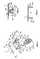
- this second embodiment differs from the first embodiment mainly for the configuration of the retaining elements.
- the retaining elements 300 include tabs 302, facing and opposite to each other, which are associated to the wall portions 201 in the region of the opening 203.
- the tabs 302 are converging and in a spaced apart relationship up to a minimum distance L2.
- the tabs 302 are formed as a single piece with each wall 20 and are projecting, with respect to the wall 20, by respective bends K.
- the tabs 302 are bent converging to the outside, in a direction opposite to the housing A, and form an angle of about 45° with respect to the wall 20.
- the tabs 302 can deform elastically.
- the tabs 302 can rotate with respect to the bend K, and expand to facilitate the insertion of the rotation pin 31.
- the walls 20 include each a nook or indentation 320, interposed between a respective tab 302 and the rotation seat 204.
- the tabs 302 hold the pin 3 to prevent a coming out thereof from the rotation seat 204.
- appendages 210 or deep-drawn parts are associated to the walls 20 in the region of the rotation seats 204, the appendages 210 extending along the rotation seat 204.
- the appendages 210 are edges or portions of sheet metal arranged along the semicircular profile of the rotation seats 204, oriented orthogonally with respect to the walls 20.
- the appendages 210 are prolongations or extensions of the walls 20 facing the opposite side with respect to the housing A.
- the appendages 210 increase the contact surface or zone intended to receive the rotation pins 31 of the wheels 3.
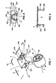
- FIG. 10-12 a third embodiment of the support and movement equipment 110 is illustrated.
- this embodiment differs from the preceding embodiments in that the rotation seat 114 is obtained in the support plate 2, rather than in the walls 20, i.e. the support plate 2 includes the rotation seat 114.
- the rotation seat 114 may be obtained on the support plate 2 so that a portion 115 of the material of the support plate 2, separated from the remainder of support plate 2, be bent and sharply curved with respect to the support plate 2. More specifically, the portion 115 is cut with respect to the support plate 2.
- the walls 20 can have an extension smaller than the walls 20 of the preceding embodiments. Moreover, such walls 20, analogously to the first embodiment of the support and movement equipment 1, have the above-mentioned edges 301 for retaining the pin 31 in the rotation seat 114.
- FIG. 13-17 a fourth embodiment of the support and movement equipment 1010 is illustrated.
- this embodiment differs from the preceding embodiments in that the opening 203 is interposed between the support plate 2 and each wall 20, so that the wheel 3 be inserted from the side of the support plate 2, toward the rotation seat 204 which is associated to each wall 20.
- appendages or deep-drawn parts 210 are present, extending along the rotation seat 204.
- the appendages 210 are sheet metal edges or portions arranged along the semicircular profile of the rotation seats 204, oriented orthogonally with respect to the walls 20.
- the opening 203 extends to the region of the support plate 2, to form a window 1002 in the support plate 2. Retaining tabs or lobes 1301 are obtained in the support plate 2, in the region of said window 1002, to contain any motion of the pin 31.
- the wheel or roller 3 and the rotation pin 31 form a single piece, and are made of abrasion-resistant material, like e.g. Teflon.
- the rotation pin 31 has an axis of rotation R and, coherently to the geometry of the parts described above, is received with adequate clearance/play in the rotation seat 24 to allow rotation, and has a diameter D2 greater than the distance L1 between the lobes 301, 1301 and than the minimum distance L2 between the tabs 302.
- the rotation pin 31 is made of a material different with respect to the material of which the wheel is made, and is firmly assembled to the wheel 3 so as to form an individually manipulable single body.
- the wheel 3 may be made by co-injection of a wheel of plastic with a pin of metal, such as, e.g., iron or steel.
- the wheel 3 further includes a contact zone 32, intended for rolling on a surface or floor P.
- the support plate 2 is made of a material harder that the material of the wheel 3.
- the same support plate 2 is made so as not to be able to deform.
- the rotation pin 31 is arranged and inserted in the two openings 203. From this position, by applying a force along the insertion path L orthogonally to the axis of rotation R (toward the support plate 2 in the embodiments of Figures 2-12 and toward the walls 20 in the embodiments of Figures 13-17 ), the rotation pin 31 and the lobes 301, 1301, or the tabs 302, deform elastically.
- the rotation pin 31 cannot come out of the rotation seat 204, 114, owing to the presence of the lobes 301, 1301, or of the tabs 302, after those have returned to an undeformed condition.
- the support and movement equipment according to the present disclosure can make the support and movement equipment more inexpensive.
- the support and movement equipment crossbar-shaped and including only one plate and two wheel-pin units as schematically indicated in Figure 1 , can be of easy and rapid production.
- the described support and movement equipment can reduce costs and times associated to the maintenance of such a device. For instance, in case of wheel wear or breakage, it is possible to replace it in a short time, by applying to the wheel a pull in a direction opposite to that applied during the assembling. Once the wheel has been removed from the housing, it is possible to rapidly proceed with the assembling of a new wheel.
- the described support and movement equipment can reduce wear of the parts, and in particular of the wheel.
- the deep-drawn parts associated to the rotation seats in fact widen the contact surface between the rotation pin and the housing, decreasing wear and therefore the wear of the parts.
- the deep-drawn parts can moreover contribute to reduce the presence of imperfections or roughnesses in the region of the rotation seats, further decreasing the possibility of wear between constituent parts of the support and movement equipment.
Landscapes
- Engineering & Computer Science (AREA)
- Mechanical Engineering (AREA)
- Chemical & Material Sciences (AREA)
- Combustion & Propulsion (AREA)
- Physics & Mathematics (AREA)
- Thermal Sciences (AREA)
- General Engineering & Computer Science (AREA)
- Pivots And Pivotal Connections (AREA)
Priority Applications (1)
| Application Number | Priority Date | Filing Date | Title |
|---|---|---|---|
| EP11176309A EP2554931A1 (fr) | 2011-08-02 | 2011-08-02 | Support et équipement de mouvement |
Applications Claiming Priority (1)
| Application Number | Priority Date | Filing Date | Title |
|---|---|---|---|
| EP11176309A EP2554931A1 (fr) | 2011-08-02 | 2011-08-02 | Support et équipement de mouvement |
Publications (1)
| Publication Number | Publication Date |
|---|---|
| EP2554931A1 true EP2554931A1 (fr) | 2013-02-06 |
Family
ID=45571310
Family Applications (1)
| Application Number | Title | Priority Date | Filing Date |
|---|---|---|---|
| EP11176309A Withdrawn EP2554931A1 (fr) | 2011-08-02 | 2011-08-02 | Support et équipement de mouvement |
Country Status (1)
| Country | Link |
|---|---|
| EP (1) | EP2554931A1 (fr) |
Cited By (2)
| Publication number | Priority date | Publication date | Assignee | Title |
|---|---|---|---|---|
| US10473262B2 (en) * | 2016-12-07 | 2019-11-12 | Bsh Hausgeraete Gmbh | Household refrigeration appliance with non-destructively releasable roller assembly in the base of a housing and method for producing the household refrigeration appliance |
| WO2020013913A1 (fr) * | 2018-07-12 | 2020-01-16 | Igloo Products Corp. | Récipient contenant un ensemble roues sans axe |
Citations (3)
| Publication number | Priority date | Publication date | Assignee | Title |
|---|---|---|---|---|
| US4255074A (en) * | 1978-07-25 | 1981-03-10 | Meccanotecnica S.P.A. | Palletizing machine |
| US5711162A (en) * | 1996-04-09 | 1998-01-27 | Maytag Corporation | Refrigerator compressor mounting pan arrangement |
| EP1725820A1 (fr) * | 2004-03-01 | 2006-11-29 | Whirlpool Corporation | Dispositif de support multifonctionnel pour appareils electromenagers tels que congelateurs, refrigerateurs et autres |
-
2011
- 2011-08-02 EP EP11176309A patent/EP2554931A1/fr not_active Withdrawn
Patent Citations (3)
| Publication number | Priority date | Publication date | Assignee | Title |
|---|---|---|---|---|
| US4255074A (en) * | 1978-07-25 | 1981-03-10 | Meccanotecnica S.P.A. | Palletizing machine |
| US5711162A (en) * | 1996-04-09 | 1998-01-27 | Maytag Corporation | Refrigerator compressor mounting pan arrangement |
| EP1725820A1 (fr) * | 2004-03-01 | 2006-11-29 | Whirlpool Corporation | Dispositif de support multifonctionnel pour appareils electromenagers tels que congelateurs, refrigerateurs et autres |
Cited By (4)
| Publication number | Priority date | Publication date | Assignee | Title |
|---|---|---|---|---|
| US10473262B2 (en) * | 2016-12-07 | 2019-11-12 | Bsh Hausgeraete Gmbh | Household refrigeration appliance with non-destructively releasable roller assembly in the base of a housing and method for producing the household refrigeration appliance |
| WO2020013913A1 (fr) * | 2018-07-12 | 2020-01-16 | Igloo Products Corp. | Récipient contenant un ensemble roues sans axe |
| CN112424547A (zh) * | 2018-07-12 | 2021-02-26 | 伊格鲁产品公司 | 具有无轮轴车轮组件的容器 |
| JP2021530410A (ja) * | 2018-07-12 | 2021-11-11 | イグルー プロダクツ コーポレイション | 車軸のないホイールアセンブリを有する容器 |
Similar Documents
| Publication | Publication Date | Title |
|---|---|---|
| EP2248442A1 (fr) | Ensemble stabilisant pour support amovible | |
| EP2594159A2 (fr) | Ensemble coulissant guidé | |
| CN106163825B (zh) | 双重锁定式脚轮 | |
| US11332315B2 (en) | Link for a chain for an article conveyor | |
| US8997976B2 (en) | Assembly for supporting and guiding conveyor belts | |
| EP2554931A1 (fr) | Support et équipement de mouvement | |
| EP1279355A3 (fr) | Armoire pour convoyer des médicaments | |
| KR100921138B1 (ko) | 볼 베어링용 리테이너 및 리테이너 제조 방법 | |
| CN105731037A (zh) | 方向转换自动转向器 | |
| CA2846691C (fr) | Rouleau de galetage | |
| JP2015510861A (ja) | コンベヤチェーンリンク、コンベヤチェーン、コンベヤチェーン用の駆動ホイール、及びそのような駆動ホイールを備えるシステム | |
| JP2012121057A (ja) | 動力伝達チェーン用ピンの組立治具 | |
| CN107956528A (zh) | 可变气门传动装置的中间杠杆 | |
| US2038095A (en) | Retainer for antifriction bearings | |
| KR101177845B1 (ko) | 탄성링 베어링 | |
| EP2554354A1 (fr) | Système de centrage de moule | |
| KR101277660B1 (ko) | 탄성링 베어링 | |
| EP2299187B1 (fr) | Support d'angle | |
| WO2016094471A1 (fr) | Chaîne à rouleaux et axes | |
| JP5456990B2 (ja) | チェーンコンベヤ | |
| CN211495856U (zh) | 一种自动排列机构 | |
| CN101644311B (zh) | 张紧装置 | |
| EP1977983A1 (fr) | Chaîne fournie avec des pivots pour transporter un matériau de feuille | |
| JP5864645B2 (ja) | 遊技機 | |
| CN110671470B (zh) | 一种传动链 |
Legal Events
| Date | Code | Title | Description |
|---|---|---|---|
| PUAI | Public reference made under article 153(3) epc to a published international application that has entered the european phase |
Free format text: ORIGINAL CODE: 0009012 |
|
| AK | Designated contracting states |
Kind code of ref document: A1 Designated state(s): AL AT BE BG CH CY CZ DE DK EE ES FI FR GB GR HR HU IE IS IT LI LT LU LV MC MK MT NL NO PL PT RO RS SE SI SK SM TR |
|
| AX | Request for extension of the european patent |
Extension state: BA ME |
|
| 17P | Request for examination filed |
Effective date: 20130802 |
|
| RBV | Designated contracting states (corrected) |
Designated state(s): AL AT BE BG CH CY CZ DE DK EE ES FI FR GB GR HR HU IE IS IT LI LT LU LV MC MK MT NL NO PL PT RO RS SE SI SK SM TR |
|
| STAA | Information on the status of an ep patent application or granted ep patent |
Free format text: STATUS: THE APPLICATION IS DEEMED TO BE WITHDRAWN |
|
| 18D | Application deemed to be withdrawn |
Effective date: 20160503 |