EP2554936A2 - Appareil échangeur de chaleur à dégivrage et procédé associé - Google Patents
Appareil échangeur de chaleur à dégivrage et procédé associé Download PDFInfo
- Publication number
- EP2554936A2 EP2554936A2 EP20120178979 EP12178979A EP2554936A2 EP 2554936 A2 EP2554936 A2 EP 2554936A2 EP 20120178979 EP20120178979 EP 20120178979 EP 12178979 A EP12178979 A EP 12178979A EP 2554936 A2 EP2554936 A2 EP 2554936A2
- Authority
- EP
- European Patent Office
- Prior art keywords
- heat exchanger
- blockage
- liquid
- flow
- heat
- Prior art date
- Legal status (The legal status is an assumption and is not a legal conclusion. Google has not performed a legal analysis and makes no representation as to the accuracy of the status listed.)
- Granted
Links
Images

Classifications
-
- F—MECHANICAL ENGINEERING; LIGHTING; HEATING; WEAPONS; BLASTING
- F28—HEAT EXCHANGE IN GENERAL
- F28F—DETAILS OF HEAT-EXCHANGE AND HEAT-TRANSFER APPARATUS, OF GENERAL APPLICATION
- F28F17/00—Removing ice or water from heat-exchange apparatus
-
- F—MECHANICAL ENGINEERING; LIGHTING; HEATING; WEAPONS; BLASTING
- F28—HEAT EXCHANGE IN GENERAL
- F28F—DETAILS OF HEAT-EXCHANGE AND HEAT-TRANSFER APPARATUS, OF GENERAL APPLICATION
- F28F19/00—Preventing the formation of deposits or corrosion, e.g. by using filters or scrapers
- F28F19/006—Preventing deposits of ice
-
- F—MECHANICAL ENGINEERING; LIGHTING; HEATING; WEAPONS; BLASTING
- F28—HEAT EXCHANGE IN GENERAL
- F28F—DETAILS OF HEAT-EXCHANGE AND HEAT-TRANSFER APPARATUS, OF GENERAL APPLICATION
- F28F27/00—Control arrangements or safety devices specially adapted for heat-exchange or heat-transfer apparatus
- F28F27/02—Control arrangements or safety devices specially adapted for heat-exchange or heat-transfer apparatus for controlling the distribution of heat-exchange media between different channels
Definitions
- the embodiments of the present disclosure relate generally to heat exchangers and, more particularly, to defrostable heat exchangers and associated methods.
- a heat exchanger may be configured to cool relatively warm air.
- the heat exchanger may receive warm air along with a cool liquid. Heat from the air may be absorbed by the liquid so as to cool the air and heat the liquid. As such, cooler air may exit from the heat exchanger along with a warmer liquid following the heat exchange therebetween.
- a heat exchanger may include a plurality of first channels through which the liquid passes and a plurality of second channels through which the air flows. These channels may be mutually exclusive, but may be arranged and constructed so as to facilitate heat exchange between the air and the liquid passing through the respective channels.
- the first and second channels through which the liquid and air flow, respectively may be positioned in an alternating fashion such that a common wall separates a channel through which liquid passes from a channel through which air flows, thereby facilitating heat exchange between the liquid and the air.
- the heat exchanger may include fins, such as fins extending from the walls that define the respective channels into, for example, the channels through which the air flows in order to facilitate heat exchange therebetween.
- the liquid that is provided to the heat exchanger has a temperature lower than the freezing temperature of water in order to provide for more effective heat transfer.
- liquid that condenses from the warm, humid air that is received by the heat exchanger for cooling may freeze within the heat exchanger.
- the build up of ice within the heat exchanger will limit the cooling capacity of the heat exchanger by limiting the amount of air that may flow through the heat exchanger.
- sufficient amounts of ice may form within the heat exchanger so as to prevent air from flowing through the heat exchanger, thereby eliminating further heat exchange.
- the system may be designed such that the liquid provided to the heat exchanger has a temperature above the freezing temperature of water.
- the heat exchanger may be positioned at the end of a cooling circuit so that the liquid provided to the heat exchanger is above the freezing temperature of water.
- this technique generally requires additional plumbing and more complex controls and sensors, thereby disadvantageously increasing the weight of the system.
- the increase in weight may, in turn, disadvantageously affect the performance of the vehicle.
- the cooling capacity of the heat exchanger is disadvantageously limited by requiring the liquid to remain above the freezing temperature of water.
- the use of liquid having a temperature above the freezing temperature of water will generally disadvantageously increase the air temperature at the exit of the heat exchanger, thereby potentially decreasing overall system performance.
- the heat exchanger may be periodically taken out of service and defrosted.
- the heat exchanger may be taken out of service by halting the flow of cool liquid to the heat exchanger. By continuing to provide warm air to the heat exchanger, the heat exchanger may be defrosted. By taking the heat exchanger out of service, however, the heat exchanger is unable to perform its function, thereby reducing quantity of air that is cooled and preventing continuous operation.
- a heat exchanging apparatus and an associated method are provided so as to permit a heat exchanger to be defrosted without being taken out of service.
- a heat exchanger may continue to exchange heat between a gas and a liquid that flow through the heat exchanger while the heat exchanger is being defrosted.
- the heat exchanging apparatus and associated method may reduce icing within a heat exchanger while permitting the heat exchanger to continue to function.
- the heat exchanging apparatus and method of one embodiment permits the cool liquid to be provided at a temperature below the freezing temperature of water in order to improve the cooling efficiency of the system since any ice build up may be readily defrosted.
- a defrostable heat exchanging apparatus in one embodiment, includes a heat exchanger configured to cool gas flowing therethrough by heating a liquid also passing therethrough.
- the defrostable heat exchanging apparatus of this embodiment also includes a blockage positionable upstream of the heat exchanger with respect to the liquid so as to reduce flow of the liquid through a portion of the heat exchanger aligned with the blockage relative to the flow of the liquid through other portions of the heat exchanger.
- the heat exchanger may be configured such that the liquid flows from a first side to a second side of the heat exchanger with the blockage being smaller than the first side of the heat exchanger so as to only block a portion of the heat exchanger.
- the defrostable heat exchanging apparatus may include a positioning mechanism for moving the blockage relative to the heat exchanger.
- the positioning mechanism may be configured to be actuated by the flow of liquid so as to move the blockage relative to the heat exchanger.
- the positioning mechanism may include a chain and a plurality of sprockets about which the chain extends with the blockage being engaged by the chain so as to move therewith.
- the positioning mechanism may also include at least one of a Pelton wheel or a water wheel operably connected to a respective sprocket.
- the defrostable heat exchanging apparatus may also include a control valve configured to control the flow of liquid to the at least one of the Pelton wheel or the water wheel in order to controllably move the chain and position the blockage.
- the blockage may be positionable outside of the flow of the liquid through the heat exchanger.
- the defrostable heat exchanging apparatus may include a blockage sensor configured to detect a presence of the blockage outside of the flow of the liquid through the heat exchanger.
- a defrostable heat exchanging apparatus in another embodiment, includes a heat exchanger configured to cool gas flowing therethrough by heating a liquid also passing therethrough.
- the heat exchanger is configured such that the liquid passes from a first side to a second side of the heat exchanger.
- the defrostable heat exchanging apparatus of this embodiment also includes a blockage positionable upstream of the first side of the heat exchanger with respect to the liquid so as to reduce flow of the liquid through a portion of the heat exchanger aligned with the blockage relative to the flow of the liquid through other portions of the heat exchanger.
- the blockage is smaller than the first side of the heat exchanger so as to only block a portion of the heat exchanger.
- the defrostable heat exchanging apparatus of this embodiment also includes a positioning mechanism configured to move the blockage relative to the heat exchanger, such as in response to the flow of liquid.
- the positioning mechanism of one embodiment may include a chain and a plurality of sprockets about which the chain extends with the blockage being engaged by and moving with the chain.
- the positioning mechanism may also include at least one of a Pelton wheel or a water wheel operably connected to a respective sprocket.
- the blockage is positionable outside of the flow of the liquid through the heat exchanger.
- the defrostable heat exchanging apparatus may include a blockage sensor configured to detect a presence of the blockage outside of the flow of the liquid through the heat exchanger.
- a method of defrosting a heat exchanger that allows gas to flow through the heat exchanger, allows liquid to also pass through the heat exchanger so as to cool the gas and positions a blockage upstream of the heat exchanger with respect to the liquid so as to reduce the flow of the liquid through a portion of the heat exchanger aligned with the blockage relative to the flow of the liquid through other portions of the heat exchanger.
- the method also moves the blockage relative to the heat exchanger.
- the blockage may be moved by actuating movement of the blockage by the flow of liquid.
- the blockage may be moved by controlling the flow of liquid so as to controllably move the blockage.
- a portion of the flow of liquid may be controllably diverted so as to controllably move the blockage.
- the method of one embodiment may also include positioning the blockage outside of the flow of the liquid through the heat exchanger. As such, the method may move the blockage from a position outside of the flow of liquid through the heat exchanger across a width of the heat exchanger.
- a defrostable heat exchanging apparatus and an associated method are provided in order to permit a heat exchanger to be defrosted without being taken out of service, thereby allowing the heat exchanger to continue to exchange heat between a gas and a liquid while defrosting a portion of the heat exchanger.
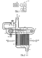
- FIG. 1 a block diagram of a heat exchanging apparatus 10 in accordance with one embodiment of the present disclosure is depicted.
- the heat exchanging apparatus 10 is configured to exchange heat between a liquid and a gas, such as air.
- the heat exchanging apparatus 10 includes a heat exchanger 12.
- warm gas enters one side of the heat exchanger 12 such as the left side of the illustrated embodiment, flows through the heat exchanger and then exits from another side of the heat exchanger, such as the right side in the embodiment of Figure 2 .
- the heat exchanger 12 includes a plurality of first channels 40 through which the gas flows that extend from the side at which the warm gas enters the heat exchanger 12 to the side at which the gas exits the heat exchanger.
- the heat exchanger 12 also receives a cool liquid which enters, for example, via a different side of the heat exchanger, such as the top side as shown in the embodiment of Figure 2 .
- the cool liquid has a lower temperature than the temperature of the gas so as to absorb heat therefrom.
- the liquid also passes through the heat exchanger 12 and exits through another side of the heat exchanger, such as the bottom side of the heat exchanger shown in the embodiment of Figure 2 .
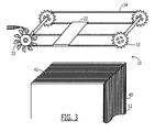
- the heat exchanger 12 also includes a plurality of second channels 42 extending from the side at which the liquid enters the heat exchanger to the side at which the liquid exits the heat exchanger, as shown in Figure 3 .
- the gas and the liquid are physically separated from one another but are in thermal communication with one another. As such, heat may be transferred therebetween.
- heat may be transferred from the warm gas to the cold liquid such that chilled gas exits the heat exchanger as well as warmer liquid.
- the temperature of the liquid is less than the temperature of the gas and, more particularly, the temperature of the warmer liquid that exits the heat exchanger 12 is generally lower than the temperature of the chilled gas that exits the heat exchanger.
- the plurality of first and second channels 40, 42 may be positioned in an alternating relationship such that a first channel through which gas flows is positioned between a pair of second channels through which liquid passes.
- a second channel 42 through which liquid passes is positioned between a pair of first channels 40 through which gas flows.
- a common wall may separate adjacent channels, such as by separating a first channel 40 through which gas flows from a second channel 42 through which liquid passes.
- a thermally conductive material such as an aluminum alloy, a steel alloy, a super alloy, e.g., an Inconel® alloy, a thermoplastic, e.g. polyetheretherketone (PEEK), or the like, heat may be transferred between the gas and the liquid through the channel walls.
- the heat exchanger 12 may include a plurality of fins extending into the respective channels from the walls that define the channels.
- a plurality of fins may extend from the walls into the first channels 40 through which the gas flows, thereby further facilitating the heat exchange between the gas and the liquid.
- a liquid may at least sometimes be provided to the heat exchanger 10 that is at a temperature below the freezing temperature of water.
- water that condenses from the warm, humid gas may freeze within the heat exchanger 12 and, more particularly, within the first channels 40 through which the gas flows.
- the heat exchanging apparatus 10 provides a mechanism for defrosting the heat exchanger 12, thereby melting any liquid that freezes within the heat exchanger.
- the heat exchanging apparatus 10 continues to permit gas and liquid to be provided to the heat exchanger 12 and does not require the heat exchanger to be taken out of service.
- the heat exchanging apparatus 10 may include a positioning mechanism 20 that, in turn, includes or controls a blockage 22, as shown schematically in Figure 1 .
- the blockage 22 is positioned upstream of the heat exchanger 12 with respect to the flow of the liquid, as shown in Figures 2 and 3 .
- the blockage 22 is positioned proximate the side of the heat exchanger 12 that receives the cool liquid.
- the blockage 22 does not extend across the entire side of the heat exchanger 12 and, instead, only covers or blocks a portion of the side that receives the cool liquid.
- the blockage 22 may be formed of various materials, such as any of the materials described above in conjunction with the walls of the heat exchanger.
- the blockage 22 may be formed of a solid material so as to prevent or at least limit the flow of liquid through the second channels 42 that are aligned with and blocked by the blockage.
- the blockage 22 may be porous, such as by including a plurality of openings or being formed of a porous material, for discouraging, but not preventing, flow of the liquid through the second channels 42 that are aligned with and blocked by the blockage.
- the blockage 22 may be perforated or may be a screen. Regardless of whether the blockage 22 is solid or is porous, the blockage in the embodiment of Figure 1 is aligned with a subset 24 of the second channels 42, thereby preventing or at least limiting the flow of liquid through the second channels aligned with the blockage.
- the blockage 22 has a width that is less than 50% of the width of the first side of the heat exchanger 12 through which the liquid enters and, in one embodiment, is less than or equal to about 25% of the width of the first side of the heat exchanger. However, the blockage 22 may be larger or smaller in other embodiments.
- the warm gas that enters the heat exchanger 12 serves to defrost the subset 24 of first channels 40 that are aligned with the blockage.
- ice that has formed within the subset 24 of the first channels 40 through which gas flows that is aligned with the blockage 22 may be melted by the warm gas.
- the amount of gas that may flow through the heat exchanger 12 may be increased by the defrosting of the portion of the heat exchanger aligned with the blockage 22.
- the blockage 22 may, in turn, be moved across the width of the heat exchanger 12 so as to permit other portions of the heat exchanger to be defrosted in the manner described below.
- the blockage 22 may be positioned proximate the heat exchanger 12 and moved across its width in various manners.
- the positioning mechanism 20 may be configured to cause the blockage 22 to be hydraulically actuated, such as by means of a Pelton wheel as described below in conjunction with the illustrated embodiment, a vaned pump, reciprocating pistion(s) or the like.
- the positioning mechanism 20 may be configured to cause the blockage 22 to be electrically actuated, such as by means of a stepper motor, an AC motor, a DC motor or the like.
- the positioning mechanism 20 may be configured to cause the blockage 22 to be pneumatically actuated.
- a positioning mechanism 20 configured to hydraulically actuate the blockage 22 utilizing, for example, a Pelton wheel, will now be described for purposes of example, but not of limitation.
- the positioning mechanism 20 may include a plurality of sprockets 32 connected by respective shafts.
- first and second pairs of sprockets 32 may be positioned on opposite sides of the heat exchanger 12 with each respective pair of sprockets connected by a shaft.
- the sprockets 32 are generally positioned outboard of the heat exchanger 12 such that the sprockets do not interrupt the flow of liquid to the heat exchanger.
- the positioning mechanism of one embodiment also includes a pair of chains, belts or other conveying mechanisms (hereinafter generically referred to as "chains 34") that extend about a respective pair of sprockets (with the sprockets of each pair being positioned on opposite sides of the heat exchanger 12) so as to form an endless path of travel therearound.
- the chains 34 may also be positioned outboard of the heat exchanger 12 so as not to block the flow of liquid to the heat exchanger.
- the chains 34 of one embodiment may also or alternatively include a plurality of openings therethrough so facilitate the passage of liquid through the chains.
- the blockage 22 of this embodiment is carried by the chains 34, such as by extending between the chains so as to be engaged by and connected to the chains, thereby moving with the chains as the sprockets 32 rotate.
- the blockage 22 may, in turn, be controllably moved relative to the heat exchanger 12, such as across the width of the heat exchanger.
- the motive force for moving the blockage 22 may be provided in various manners as noted above, the positioning mechanism 20 of one embodiment may be hydraulically actuated and, as such, may utilize liquid that enters the heat exchanger 12 to move the blockage in one embodiment.
- the positioning mechanism 20 may also include a Pelton wheel 33 or water wheel operably connected to a respective sprocket 32, either directly, via one or more gears or otherwise.
- a Pelton wheel 33 or water wheel operably connected to a respective sprocket 32, either directly, via one or more gears or otherwise.
- the Pelton wheel or water wheel is rotated which, in turn, causes the sprocket 32 that is operably connected thereto to be rotated so as to move the chains 34 and the blockage 22 relative to the heat exchanger.
- the Pelton wheel 33 may be positioned outside of the primary flow of liquid to the heat exchanger 12, but is positioned so as to receive the liquid diverted through a side channel 30 as described below.
- the heat exchanging apparatus 10 of the illustrated embodiment includes a control valve 28 for controlling the flow of liquid to the Pelton wheel or the water wheel.
- a side channel 30 may be defined through which a portion of the liquid that is otherwise received by the heat exchanger 12 may be diverted.
- a control valve 28 may be positioned so as to controllably open or close the side channel 30.
- the control valve 28 may, in turn, be controlled by a control unit, such as a computing device, e.g., a computer, controller or the like.
- the side channel 30 is opened, such as by opening the control valve 28, a portion of the liquid is diverted through the side channel and is delivered to the Pelton wheel 33 or water wheel, thereby causing the sprocket 32 that is operably connected to the Pelton wheel or water wheel to be rotated and, in turn, causing the chains 34 and the blockage 22 to be moved relative to the heat exchanger 12.
- the control valve 28 may cause the side channel 30 to be closed, thereby preventing the diversion of liquid through the side channel and preventing liquid from being delivered to the Pelton wheel 33 or water wheel. In this instance, the Pelton wheel 33 or water wheel is not rotated and the blockage 22, in turn, does not move and remains fixed in position relative to the heat exchanger 12.
- the positioning mechanism 20 may controllably position the blockage 22 relative to the heat exchanger 12 so as to defrost different portions of the heat exchanger.
- the blockage 22 may also be controllably moved across the heat exchanger 12, such as at a predefined rate of travel, in order to permit different portions of the heat exchanger to be defrosted.
- the blockage 22 may be positioned outboard of the heat exchanger 12 so as not to block any liquid that would otherwise enter the heat exchanger, thereby permitting the heat exchanger to operate at maximum cooling capacity in instances in which defrosting is not required.
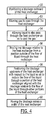
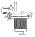
- the blockage 22 may initially be positioned outboard of the heat exchanger 12. As shown in the embodiment of Figure 5 , for example, the blockage 22 may be positioned so as not to be aligned with any portion of the heat exchanger 12.
- the heat exchanging apparatus 10 may include a blockage sensor 36 for detecting the presence of the blockage 22 in a position outboard of the heat exchanger 12.
- the blockage 22 may be advanced, such as by rotation of the sprockets 32 of the illustrated embodiment, until the blockage sensor 36 detects the blockage.
- the positioning mechanism 20 may then halt further movement of the blockage 22, at least temporarily, so as to park the blockage 22 outside of the flow of liquid through the heat exchanger 12.
- the control valve 28 may be closed so as to cause the side channel 30 to be closed, thereby preventing diversion of fluid through the side channel.
- gas may then be allowed to flow through the heat exchanger 12 and liquid may also be allowed to concurrently flow through the heat exchanger.
- warm gas and a cool liquid may be provided to the heat exchanger 12 such that heat is exchanged therebetween in order to heat the liquid and chill the gas.
- the positioning mechanism 20 may then cause the blockage 22 to be moved relative to the heat exchanger 12 from the position outside of the flow of liquid to a position overlying a portion of the heat exchanger, such as from the position shown in Figure 5 to a position shown in Figure 2 . See operation 56.
- the positioning mechanism 20 may cause the blockage 22 to be moved in various manners, the positioning mechanism of one embodiment may cause the blockage 22 to be moved by causing the control valve 28 to be opened such that liquid is diverted through the side channels 30 so as to drive the Pelton wheel 33 or water wheel, thereby rotating the sprockets 32 and moving the blockage across the width of the heat exchanger 12.
- the blockage 22 may be positioned upstream of the heat exchanger 12 with respect to the liquid so as to reduce the flow of the liquid through a portion of the heat exchanger aligned with the blockage relative to the flow of the liquid through other portions of the heat exchanger.
- the flow of liquid through the subset 24 of second channels 42 of the heat exchanger 12 that is aligned with the blockage 22 is reduced relative to the flow of liquid through other portions 26 of the heat exchanger.
- the flow of the warm gas through the heat exchanger 12 serves to defrost that portion of the first channels 40 aligned with the blockage 22 since the cool liquid is no longer flowing therethrough, at least not in significant quantities.
- the cooling capacity of the heat exchanger 12 is maintained at a relatively high level.
- the positioning mechanism 20 may cause the blockage 22 to be moved across the width of the heat exchanger 12.
- Figure 6 illustrates the movement of the blockage 22 to another position so as to be aligned with a different portion of the heat exchanger 12.
- the blockage 22 of one embodiment may be moved relative to the heat exchanger 12 by opening the control valve 28 and diverting liquid through the side channel 30.
- the diverted liquid of this embodiment drives the rotation of the Pelton wheel 33 or water wheel which, in turn, rotates the sprockets 32 and moves the chains 34 and the blockage 22 with respect to the heat exchanger 12.
- the control valve 28 of the illustrated embodiment may be actuated, such as by the control unit, so as to control the amount of liquid diverted through the side channel 30.
- the control valve 28 may open the side channel 30 to an extent that the diverted liquid continuously drives the Pelton wheel 33 or water wheel at a rate that causes the blockage 22 to move continuously across the width of the heat exchanger 12 at a predefined velocity.
- the velocity may be defined in a manner that ensures that the flow of warm gas through that portion of the heat exchanger 12 that is aligned with the blockage 22 will defrost that portion of the heat exchanger.
- control valve 28 may control the diversion of the liquid through the side channel 30 and the driving of the Pelton wheel 33 or water wheel in such a manner that the blockage 22 is advanced in a stepwise manner across the width of the heat exchanger 12.
- the blockage 22 is positioned in a first position, such as shown in Figure 2 and the control valve 28 then closes the side channel 30 so as to prevent rotation of the Pelton wheel 33 or water wheel and to also prevent movement of the blockage. Warm gas flows through the heat exchanger 12 while the blockage 22 remains in this position so as to defrost that portion of the heat exchanger with which the blockage is aligned.
- the control valve 28 of this embodiment may be opened so as to divert liquid through the side channel 30 and to cause the Pelton wheel 33 or water wheel to rotate, thereby moving the blockage 22 to another position.
- the control valve 28 may be closed so as to again close the side channel 30 while the blockage remains in a second position and the portion of the heat exchanger 12 aligned with the second position of the blockage is defrosted. This process may be repeated in a stepwise manner until all portions of the heat exchanger 12 have been defrosted.
- Figure 6 illustrates the blockage 22 in another position subsequent to that shown in Figure 2 with another portion of the heat exchanger 12, namely, that portion 24 aligned with the blockage, being defrosted by the flow of warm gas therethrough.
- the control valve 28 may remain open so as to divert a portion of the liquid through the side channel 30 in order to continuously drive the Pelton wheel 33 or water wheel such that the blockage 22 travels with the chain 34 about the sprockets 32 so as to return to a position outboard of the heat exchanger 12, such as shown in Figure 5 .
- the control valve 28 may close the side channel 30, thereby causing the blockage to remain in the position outboard of the heat exchanger 12 until further defrosting is required.
- Defrosting of the heat exchanger 12 may be performed on a predefined schedule, such as a predefined schedule defined by the control unit which communicates with the positioning mechanism 20 which, in turn, directs the control valve 28 and responds to the blockage sensor 36 as described above.
- the heat exchanging apparatus 10 and method may include a pressure switch or a gas flow sensor for monitoring the quantity of chilled gas that exits the heat exchanger 12. As ice accumulates within the heat exchanger 12, such as within the first channels 40 through which the gas flows, the quantity of gas that exits the heat exchanger 12 may be reduced. As such, the gas flow sensor may provide information indicative of the quantity of chilled gas that exits the heat exchanger 12 to the control unit.
- the control unit may be configured to instruct the positioning mechanism 20 to open the control valve 28 and to cause the blockage 22 to be moved into a first position, such as shown in Figure 2 , aligned with a portion of the heat exchanger 12 in order to commence the defrosting operations once the information provided by the gas flow sensor indicates that the quantity of chilled gas that exits the heat exchanger has fallen below a predefined threshold that is indicative of the accumulation of ice within the heat exchanger.
- the heat exchanging apparatus 10 and method of one embodiment may controllably defrost the heat exchanger 12 while the heat exchanger continues to operate in order to cool gas flowing therethrough. Accordingly, the cooling capacity of the heat exchanger 12 may be maintained at a relatively high level while offering continuous service. Additionally, liquid having a temperature below the freezing temperature of water may be utilized in order to promote efficient heat-exchanging operations since any accumulation of ice may be readily defrosted without having to take the heat exchanging apparatus 10 offline.
Landscapes
- Engineering & Computer Science (AREA)
- Physics & Mathematics (AREA)
- Thermal Sciences (AREA)
- Mechanical Engineering (AREA)
- General Engineering & Computer Science (AREA)
- Heat-Exchange Devices With Radiators And Conduit Assemblies (AREA)
Applications Claiming Priority (1)
| Application Number | Priority Date | Filing Date | Title |
|---|---|---|---|
| US13/204,414 US9115940B2 (en) | 2011-08-05 | 2011-08-05 | Defrostable heat exchanging apparatus and associated method |
Publications (3)
| Publication Number | Publication Date |
|---|---|
| EP2554936A2 true EP2554936A2 (fr) | 2013-02-06 |
| EP2554936A3 EP2554936A3 (fr) | 2016-01-13 |
| EP2554936B1 EP2554936B1 (fr) | 2019-05-01 |
Family
ID=46829615
Family Applications (1)
| Application Number | Title | Priority Date | Filing Date |
|---|---|---|---|
| EP12178979.6A Active EP2554936B1 (fr) | 2011-08-05 | 2012-08-02 | Appareil échangeur de chaleur à dégivrage et procédé associé |
Country Status (2)
| Country | Link |
|---|---|
| US (1) | US9115940B2 (fr) |
| EP (1) | EP2554936B1 (fr) |
Families Citing this family (2)
| Publication number | Priority date | Publication date | Assignee | Title |
|---|---|---|---|---|
| US8707716B1 (en) | 2011-12-14 | 2014-04-29 | The Boeing Company | Re-circulating defrosting heat exchanger |
| US11035629B2 (en) * | 2017-06-06 | 2021-06-15 | Denso Corporation | Heat exchange apparatus |
Family Cites Families (17)
| Publication number | Priority date | Publication date | Assignee | Title |
|---|---|---|---|---|
| US2465259A (en) * | 1946-05-28 | 1949-03-22 | Alfred O Nelson | Fish scaring device |
| US4040478A (en) | 1973-10-01 | 1977-08-09 | The Boeing Company | External tube artery flexible heat pipe |
| SE419897B (sv) * | 1975-11-18 | 1981-08-31 | Munters Ab Carl | Saett foer avfrostning eller avisning av vaermevaexlare och anordning foer dess genomfoerande |
| US4748823A (en) * | 1984-12-07 | 1988-06-07 | Nippondenso Co., Ltd. | Automotive refrigerator |
| IT1259644B (it) * | 1992-04-10 | 1996-03-25 | Solis Srl | Dispositivo per il prefissaggio termico delle calze in uscita da una macchina circolare. |
| JP2000062446A (ja) * | 1998-08-20 | 2000-02-29 | Zexel Corp | 車両用空調装置 |
| US6564796B1 (en) | 2002-03-06 | 2003-05-20 | The Boeing Company | Thermal panel for passive temperature control |
| KR101088081B1 (ko) * | 2004-10-29 | 2011-11-30 | 한라공조주식회사 | 열교환기 |
| WO2006083443A2 (fr) * | 2005-02-02 | 2006-08-10 | Carrier Corporation | Echangeurs thermiques a flux parallele renfermant des elements d'insertion poreux |
| US20070227160A1 (en) | 2005-09-15 | 2007-10-04 | The Boeing Company | Hydrogen heat exchanger |
| US7837149B2 (en) | 2007-05-31 | 2010-11-23 | The Boeing Company | Wing debris detector |
| US8286696B2 (en) | 2007-06-22 | 2012-10-16 | The Boeing Company | Mechanically actuated thermal switch |
| US8265805B2 (en) | 2007-11-11 | 2012-09-11 | The Boeing Company | Method and apparatus for detecting icing conditions for an aircraft |
| US7775817B2 (en) | 2008-09-04 | 2010-08-17 | The Boeing Company | Electrical contacts for leading edge control surfaces on an aircraft |
| US8296913B2 (en) | 2009-03-30 | 2012-10-30 | The Boeing Company | Thermally switched ferromagnetic latching support system |
| US8973393B2 (en) | 2009-11-08 | 2015-03-10 | The Boeing Company | System and method for improved cooling efficiency of an aircraft during both ground and flight operation |
| US20120291459A1 (en) | 2011-05-17 | 2012-11-22 | The Boeing Company | Method and apparatus for aircraft galley cooling |
-
2011
- 2011-08-05 US US13/204,414 patent/US9115940B2/en active Active
-
2012
- 2012-08-02 EP EP12178979.6A patent/EP2554936B1/fr active Active
Non-Patent Citations (1)
| Title |
|---|
| None |
Also Published As
| Publication number | Publication date |
|---|---|
| US9115940B2 (en) | 2015-08-25 |
| EP2554936B1 (fr) | 2019-05-01 |
| EP2554936A3 (fr) | 2016-01-13 |
| US20130031917A1 (en) | 2013-02-07 |
Similar Documents
| Publication | Publication Date | Title |
|---|---|---|
| US8341951B2 (en) | Vehicle exhaust heat recovery with multiple coolant heating modes and method of managing exhaust heat recovery | |
| EP2304367B1 (fr) | Tour de refroidissement humide/sèche et procédé associé | |
| JP5800894B2 (ja) | 冷却塔を有する冷却装置のための熱サイフォン冷却器 | |
| EP3099981B1 (fr) | Système de commande de condenseur de réfrigérant adiabatique | |
| CN103527303A (zh) | 具有冷却流动模式的动力传动系冷却系统 | |
| US20100319878A1 (en) | Multilateral continuous uniform rapid cooling device of double cooling structure | |
| US4244422A (en) | Method and device for defrosting heat exchanger without impairment of its heat exchange efficiency | |
| EP2554936B1 (fr) | Appareil échangeur de chaleur à dégivrage et procédé associé | |
| EP3988872B1 (fr) | Ensemble de fabrication de glace | |
| EP3402971B1 (fr) | Agencement de ventilateur dans un véhicule | |
| EP3670909B1 (fr) | Machine de refroidissement d'air | |
| ITBO20110384A1 (it) | Impianto frigorifero a refrigerante naturale. | |
| SE533145C2 (sv) | Metod och system för lagring av kyla i ett fordons AC-system. | |
| US8443594B2 (en) | Method of controlling temperature of a thermoelectric generator in an exhaust system | |
| EP4118384B1 (fr) | Unité de refroidissement libre pour système de gestion de température | |
| SE536208C2 (sv) | Luftbehandlingssystem och sätt att styra avfrostningen av detta | |
| US11278845B2 (en) | Gas dehumidification device and transport means having a gas dehumidification device | |
| KR20120001428A (ko) | 차량의 배기열 회수장치 | |
| EP3524919B1 (fr) | Système de dégivrage d'échangeur de chaleur d'aéronef | |
| SE1050164A1 (sv) | Arrangemang för avisning av en laddluftkylare | |
| JP7352834B2 (ja) | 冷却システム | |
| RU2553007C1 (ru) | Теплоутилизатор | |
| CN110145910B (zh) | 一种高效冷却机 | |
| RU2176365C1 (ru) | Способ работы теплообменника-утилизатора | |
| CN101131253A (zh) | 避免结霜的寒区新风换气机 |
Legal Events
| Date | Code | Title | Description |
|---|---|---|---|
| PUAI | Public reference made under article 153(3) epc to a published international application that has entered the european phase |
Free format text: ORIGINAL CODE: 0009012 |
|
| 17P | Request for examination filed |
Effective date: 20120802 |
|
| AK | Designated contracting states |
Kind code of ref document: A2 Designated state(s): AL AT BE BG CH CY CZ DE DK EE ES FI FR GB GR HR HU IE IS IT LI LT LU LV MC MK MT NL NO PL PT RO RS SE SI SK SM TR |
|
| AX | Request for extension of the european patent |
Extension state: BA ME |
|
| PUAL | Search report despatched |
Free format text: ORIGINAL CODE: 0009013 |
|
| AK | Designated contracting states |
Kind code of ref document: A3 Designated state(s): AL AT BE BG CH CY CZ DE DK EE ES FI FR GB GR HR HU IE IS IT LI LT LU LV MC MK MT NL NO PL PT RO RS SE SI SK SM TR |
|
| AX | Request for extension of the european patent |
Extension state: BA ME |
|
| RIC1 | Information provided on ipc code assigned before grant |
Ipc: F28F 17/00 20060101AFI20151207BHEP Ipc: F28F 19/00 20060101ALI20151207BHEP Ipc: F28F 27/02 20060101ALI20151207BHEP |
|
| GRAP | Despatch of communication of intention to grant a patent |
Free format text: ORIGINAL CODE: EPIDOSNIGR1 |
|
| STAA | Information on the status of an ep patent application or granted ep patent |
Free format text: STATUS: GRANT OF PATENT IS INTENDED |
|
| INTG | Intention to grant announced |
Effective date: 20180622 |
|
| GRAJ | Information related to disapproval of communication of intention to grant by the applicant or resumption of examination proceedings by the epo deleted |
Free format text: ORIGINAL CODE: EPIDOSDIGR1 |
|
| STAA | Information on the status of an ep patent application or granted ep patent |
Free format text: STATUS: REQUEST FOR EXAMINATION WAS MADE |
|
| INTC | Intention to grant announced (deleted) | ||
| GRAP | Despatch of communication of intention to grant a patent |
Free format text: ORIGINAL CODE: EPIDOSNIGR1 |
|
| STAA | Information on the status of an ep patent application or granted ep patent |
Free format text: STATUS: GRANT OF PATENT IS INTENDED |
|
| INTG | Intention to grant announced |
Effective date: 20181123 |
|
| GRAS | Grant fee paid |
Free format text: ORIGINAL CODE: EPIDOSNIGR3 |
|
| GRAA | (expected) grant |
Free format text: ORIGINAL CODE: 0009210 |
|
| STAA | Information on the status of an ep patent application or granted ep patent |
Free format text: STATUS: THE PATENT HAS BEEN GRANTED |
|
| AK | Designated contracting states |
Kind code of ref document: B1 Designated state(s): AL AT BE BG CH CY CZ DE DK EE ES FI FR GB GR HR HU IE IS IT LI LT LU LV MC MK MT NL NO PL PT RO RS SE SI SK SM TR |
|
| REG | Reference to a national code |
Ref country code: GB Ref legal event code: FG4D |
|
| REG | Reference to a national code |
Ref country code: CH Ref legal event code: EP Ref country code: AT Ref legal event code: REF Ref document number: 1127519 Country of ref document: AT Kind code of ref document: T Effective date: 20190515 |
|
| REG | Reference to a national code |
Ref country code: DE Ref legal event code: R096 Ref document number: 602012059517 Country of ref document: DE |
|
| REG | Reference to a national code |
Ref country code: IE Ref legal event code: FG4D |
|
| REG | Reference to a national code |
Ref country code: NL Ref legal event code: MP Effective date: 20190501 |
|
| REG | Reference to a national code |
Ref country code: LT Ref legal event code: MG4D |
|
| PG25 | Lapsed in a contracting state [announced via postgrant information from national office to epo] |
Ref country code: ES Free format text: LAPSE BECAUSE OF FAILURE TO SUBMIT A TRANSLATION OF THE DESCRIPTION OR TO PAY THE FEE WITHIN THE PRESCRIBED TIME-LIMIT Effective date: 20190501 Ref country code: AL Free format text: LAPSE BECAUSE OF FAILURE TO SUBMIT A TRANSLATION OF THE DESCRIPTION OR TO PAY THE FEE WITHIN THE PRESCRIBED TIME-LIMIT Effective date: 20190501 Ref country code: PT Free format text: LAPSE BECAUSE OF FAILURE TO SUBMIT A TRANSLATION OF THE DESCRIPTION OR TO PAY THE FEE WITHIN THE PRESCRIBED TIME-LIMIT Effective date: 20190901 Ref country code: SE Free format text: LAPSE BECAUSE OF FAILURE TO SUBMIT A TRANSLATION OF THE DESCRIPTION OR TO PAY THE FEE WITHIN THE PRESCRIBED TIME-LIMIT Effective date: 20190501 Ref country code: FI Free format text: LAPSE BECAUSE OF FAILURE TO SUBMIT A TRANSLATION OF THE DESCRIPTION OR TO PAY THE FEE WITHIN THE PRESCRIBED TIME-LIMIT Effective date: 20190501 Ref country code: NO Free format text: LAPSE BECAUSE OF FAILURE TO SUBMIT A TRANSLATION OF THE DESCRIPTION OR TO PAY THE FEE WITHIN THE PRESCRIBED TIME-LIMIT Effective date: 20190801 Ref country code: HR Free format text: LAPSE BECAUSE OF FAILURE TO SUBMIT A TRANSLATION OF THE DESCRIPTION OR TO PAY THE FEE WITHIN THE PRESCRIBED TIME-LIMIT Effective date: 20190501 Ref country code: NL Free format text: LAPSE BECAUSE OF FAILURE TO SUBMIT A TRANSLATION OF THE DESCRIPTION OR TO PAY THE FEE WITHIN THE PRESCRIBED TIME-LIMIT Effective date: 20190501 Ref country code: LT Free format text: LAPSE BECAUSE OF FAILURE TO SUBMIT A TRANSLATION OF THE DESCRIPTION OR TO PAY THE FEE WITHIN THE PRESCRIBED TIME-LIMIT Effective date: 20190501 |
|
| PG25 | Lapsed in a contracting state [announced via postgrant information from national office to epo] |
Ref country code: RS Free format text: LAPSE BECAUSE OF FAILURE TO SUBMIT A TRANSLATION OF THE DESCRIPTION OR TO PAY THE FEE WITHIN THE PRESCRIBED TIME-LIMIT Effective date: 20190501 Ref country code: BG Free format text: LAPSE BECAUSE OF FAILURE TO SUBMIT A TRANSLATION OF THE DESCRIPTION OR TO PAY THE FEE WITHIN THE PRESCRIBED TIME-LIMIT Effective date: 20190801 Ref country code: LV Free format text: LAPSE BECAUSE OF FAILURE TO SUBMIT A TRANSLATION OF THE DESCRIPTION OR TO PAY THE FEE WITHIN THE PRESCRIBED TIME-LIMIT Effective date: 20190501 Ref country code: GR Free format text: LAPSE BECAUSE OF FAILURE TO SUBMIT A TRANSLATION OF THE DESCRIPTION OR TO PAY THE FEE WITHIN THE PRESCRIBED TIME-LIMIT Effective date: 20190802 |
|
| REG | Reference to a national code |
Ref country code: AT Ref legal event code: MK05 Ref document number: 1127519 Country of ref document: AT Kind code of ref document: T Effective date: 20190501 |
|
| PG25 | Lapsed in a contracting state [announced via postgrant information from national office to epo] |
Ref country code: IS Free format text: LAPSE BECAUSE OF FAILURE TO SUBMIT A TRANSLATION OF THE DESCRIPTION OR TO PAY THE FEE WITHIN THE PRESCRIBED TIME-LIMIT Effective date: 20190901 |
|
| REG | Reference to a national code |
Ref country code: DE Ref legal event code: R082 Ref document number: 602012059517 Country of ref document: DE Representative=s name: MAIER, LL.M., MICHAEL C., DE Ref country code: DE Ref legal event code: R082 Ref document number: 602012059517 Country of ref document: DE Representative=s name: BOULT WADE TENNANT LLP, DE |
|
| PG25 | Lapsed in a contracting state [announced via postgrant information from national office to epo] |
Ref country code: EE Free format text: LAPSE BECAUSE OF FAILURE TO SUBMIT A TRANSLATION OF THE DESCRIPTION OR TO PAY THE FEE WITHIN THE PRESCRIBED TIME-LIMIT Effective date: 20190501 Ref country code: AT Free format text: LAPSE BECAUSE OF FAILURE TO SUBMIT A TRANSLATION OF THE DESCRIPTION OR TO PAY THE FEE WITHIN THE PRESCRIBED TIME-LIMIT Effective date: 20190501 Ref country code: DK Free format text: LAPSE BECAUSE OF FAILURE TO SUBMIT A TRANSLATION OF THE DESCRIPTION OR TO PAY THE FEE WITHIN THE PRESCRIBED TIME-LIMIT Effective date: 20190501 Ref country code: SK Free format text: LAPSE BECAUSE OF FAILURE TO SUBMIT A TRANSLATION OF THE DESCRIPTION OR TO PAY THE FEE WITHIN THE PRESCRIBED TIME-LIMIT Effective date: 20190501 Ref country code: CZ Free format text: LAPSE BECAUSE OF FAILURE TO SUBMIT A TRANSLATION OF THE DESCRIPTION OR TO PAY THE FEE WITHIN THE PRESCRIBED TIME-LIMIT Effective date: 20190501 Ref country code: RO Free format text: LAPSE BECAUSE OF FAILURE TO SUBMIT A TRANSLATION OF THE DESCRIPTION OR TO PAY THE FEE WITHIN THE PRESCRIBED TIME-LIMIT Effective date: 20190501 |
|
| REG | Reference to a national code |
Ref country code: DE Ref legal event code: R097 Ref document number: 602012059517 Country of ref document: DE |
|
| REG | Reference to a national code |
Ref country code: DE Ref legal event code: R082 Ref document number: 602012059517 Country of ref document: DE Representative=s name: BOULT WADE TENNANT LLP, DE |
|
| PG25 | Lapsed in a contracting state [announced via postgrant information from national office to epo] |
Ref country code: SM Free format text: LAPSE BECAUSE OF FAILURE TO SUBMIT A TRANSLATION OF THE DESCRIPTION OR TO PAY THE FEE WITHIN THE PRESCRIBED TIME-LIMIT Effective date: 20190501 Ref country code: IT Free format text: LAPSE BECAUSE OF FAILURE TO SUBMIT A TRANSLATION OF THE DESCRIPTION OR TO PAY THE FEE WITHIN THE PRESCRIBED TIME-LIMIT Effective date: 20190501 |
|
| PLBE | No opposition filed within time limit |
Free format text: ORIGINAL CODE: 0009261 |
|
| STAA | Information on the status of an ep patent application or granted ep patent |
Free format text: STATUS: NO OPPOSITION FILED WITHIN TIME LIMIT |
|
| PG25 | Lapsed in a contracting state [announced via postgrant information from national office to epo] |
Ref country code: TR Free format text: LAPSE BECAUSE OF FAILURE TO SUBMIT A TRANSLATION OF THE DESCRIPTION OR TO PAY THE FEE WITHIN THE PRESCRIBED TIME-LIMIT Effective date: 20190501 |
|
| 26N | No opposition filed |
Effective date: 20200204 |
|
| PG25 | Lapsed in a contracting state [announced via postgrant information from national office to epo] |
Ref country code: PL Free format text: LAPSE BECAUSE OF FAILURE TO SUBMIT A TRANSLATION OF THE DESCRIPTION OR TO PAY THE FEE WITHIN THE PRESCRIBED TIME-LIMIT Effective date: 20190501 |
|
| PG25 | Lapsed in a contracting state [announced via postgrant information from national office to epo] |
Ref country code: MC Free format text: LAPSE BECAUSE OF FAILURE TO SUBMIT A TRANSLATION OF THE DESCRIPTION OR TO PAY THE FEE WITHIN THE PRESCRIBED TIME-LIMIT Effective date: 20190501 Ref country code: LI Free format text: LAPSE BECAUSE OF NON-PAYMENT OF DUE FEES Effective date: 20190831 Ref country code: SI Free format text: LAPSE BECAUSE OF FAILURE TO SUBMIT A TRANSLATION OF THE DESCRIPTION OR TO PAY THE FEE WITHIN THE PRESCRIBED TIME-LIMIT Effective date: 20190501 Ref country code: CH Free format text: LAPSE BECAUSE OF NON-PAYMENT OF DUE FEES Effective date: 20190831 Ref country code: LU Free format text: LAPSE BECAUSE OF NON-PAYMENT OF DUE FEES Effective date: 20190802 |
|
| REG | Reference to a national code |
Ref country code: BE Ref legal event code: MM Effective date: 20190831 |
|
| PG25 | Lapsed in a contracting state [announced via postgrant information from national office to epo] |
Ref country code: IE Free format text: LAPSE BECAUSE OF NON-PAYMENT OF DUE FEES Effective date: 20190802 |
|
| PG25 | Lapsed in a contracting state [announced via postgrant information from national office to epo] |
Ref country code: BE Free format text: LAPSE BECAUSE OF NON-PAYMENT OF DUE FEES Effective date: 20190831 |
|
| PG25 | Lapsed in a contracting state [announced via postgrant information from national office to epo] |
Ref country code: CY Free format text: LAPSE BECAUSE OF FAILURE TO SUBMIT A TRANSLATION OF THE DESCRIPTION OR TO PAY THE FEE WITHIN THE PRESCRIBED TIME-LIMIT Effective date: 20190501 |
|
| PG25 | Lapsed in a contracting state [announced via postgrant information from national office to epo] |
Ref country code: HU Free format text: LAPSE BECAUSE OF FAILURE TO SUBMIT A TRANSLATION OF THE DESCRIPTION OR TO PAY THE FEE WITHIN THE PRESCRIBED TIME-LIMIT; INVALID AB INITIO Effective date: 20120802 Ref country code: MT Free format text: LAPSE BECAUSE OF FAILURE TO SUBMIT A TRANSLATION OF THE DESCRIPTION OR TO PAY THE FEE WITHIN THE PRESCRIBED TIME-LIMIT Effective date: 20190501 |
|
| PG25 | Lapsed in a contracting state [announced via postgrant information from national office to epo] |
Ref country code: MK Free format text: LAPSE BECAUSE OF FAILURE TO SUBMIT A TRANSLATION OF THE DESCRIPTION OR TO PAY THE FEE WITHIN THE PRESCRIBED TIME-LIMIT Effective date: 20190501 |
|
| P01 | Opt-out of the competence of the unified patent court (upc) registered |
Effective date: 20230516 |
|
| PGFP | Annual fee paid to national office [announced via postgrant information from national office to epo] |
Ref country code: DE Payment date: 20250827 Year of fee payment: 14 |
|
| PGFP | Annual fee paid to national office [announced via postgrant information from national office to epo] |
Ref country code: GB Payment date: 20250827 Year of fee payment: 14 |
|
| PGFP | Annual fee paid to national office [announced via postgrant information from national office to epo] |
Ref country code: FR Payment date: 20250825 Year of fee payment: 14 |