EP2554964A2 - Dispositif de mesure de la pression et de la température - Google Patents
Dispositif de mesure de la pression et de la température Download PDFInfo
- Publication number
- EP2554964A2 EP2554964A2 EP20120175538 EP12175538A EP2554964A2 EP 2554964 A2 EP2554964 A2 EP 2554964A2 EP 20120175538 EP20120175538 EP 20120175538 EP 12175538 A EP12175538 A EP 12175538A EP 2554964 A2 EP2554964 A2 EP 2554964A2
- Authority
- EP
- European Patent Office
- Prior art keywords
- temperature
- pressure
- measuring
- resistance
- measuring device
- Prior art date
- Legal status (The legal status is an assumption and is not a legal conclusion. Google has not performed a legal analysis and makes no representation as to the accuracy of the status listed.)
- Granted
Links
Images
Classifications
-
- G—PHYSICS
- G01—MEASURING; TESTING
- G01L—MEASURING FORCE, STRESS, TORQUE, WORK, MECHANICAL POWER, MECHANICAL EFFICIENCY, OR FLUID PRESSURE
- G01L9/00—Measuring steady of quasi-steady pressure of fluid or fluent solid material by electric or magnetic pressure-sensitive elements; Transmitting or indicating the displacement of mechanical pressure-sensitive elements, used to measure the steady or quasi-steady pressure of a fluid or fluent solid material, by electric or magnetic means
- G01L9/0041—Transmitting or indicating the displacement of flexible diaphragms
- G01L9/0051—Transmitting or indicating the displacement of flexible diaphragms using variations in ohmic resistance
- G01L9/0052—Transmitting or indicating the displacement of flexible diaphragms using variations in ohmic resistance of piezoresistive elements
- G01L9/0054—Transmitting or indicating the displacement of flexible diaphragms using variations in ohmic resistance of piezoresistive elements integral with a semiconducting diaphragm
-
- G—PHYSICS
- G01—MEASURING; TESTING
- G01K—MEASURING TEMPERATURE; MEASURING QUANTITY OF HEAT; THERMALLY-SENSITIVE ELEMENTS NOT OTHERWISE PROVIDED FOR
- G01K7/00—Measuring temperature based on the use of electric or magnetic elements directly sensitive to heat ; Power supply therefor, e.g. using thermoelectric elements
- G01K7/16—Measuring temperature based on the use of electric or magnetic elements directly sensitive to heat ; Power supply therefor, e.g. using thermoelectric elements using resistive elements
- G01K7/18—Measuring temperature based on the use of electric or magnetic elements directly sensitive to heat ; Power supply therefor, e.g. using thermoelectric elements using resistive elements the element being a linear resistance, e.g. platinum resistance thermometer
- G01K7/20—Measuring temperature based on the use of electric or magnetic elements directly sensitive to heat ; Power supply therefor, e.g. using thermoelectric elements using resistive elements the element being a linear resistance, e.g. platinum resistance thermometer in a specially-adapted circuit, e.g. bridge circuit
-
- G—PHYSICS
- G01—MEASURING; TESTING
- G01L—MEASURING FORCE, STRESS, TORQUE, WORK, MECHANICAL POWER, MECHANICAL EFFICIENCY, OR FLUID PRESSURE
- G01L19/00—Details of, or accessories for, apparatus for measuring steady or quasi-steady pressure of a fluent medium insofar as such details or accessories are not special to particular types of pressure gauges
- G01L19/0092—Pressure sensor associated with other sensors, e.g. for measuring acceleration or temperature
Definitions
- the present invention relates to a measuring device for measuring a fluid pressure and a temperature of the fluid.
- Such a combined measuring device is for example from the document DE 10 2010 012 823 A1 known.
- a pressure transducer with a housing and at least one bore formed in the housing into which a thermocouple consisting of a housing, a tube and a temperature sensor is inserted.
- a thermocouple consisting of a housing, a tube and a temperature sensor is inserted.
- the production of such a measuring device is relatively expensive and therefore expensive.
- the present invention has for its object to provide a measuring device of the type mentioned, which is inexpensive to produce.
- a measuring device having the features of claim 1 and in particular by the fact that a common, a fluid chamber and a membrane exhibiting sensor element is provided for both measurements, on the side facing away from the fluid chamber side of the membrane both a pressure measurement associated resistance -Mess Hampshire with at least one pressure-dependent resistance element for generating a bridge pressure proportional to the fluid pressure and a temperature measurement associated resistance measuring bridge with at least one temperature-dependent resistance element are each applied in thin-film technology for generating a bridge voltage proportional to the fluid temperature.
- the present invention accordingly provides a pressure transducer, which is designed as a thin-film or thin-film sensor, as well as a built-in the same technology temperature transmitter, both transducers are integrated in or on a sensor element.
- Manufacture of the pressure and temperature transducers is done in either thin-film or thin-film technology, i. by physical vapor deposition (PVD) and / or chemical vapor deposition (CVD).
- PVD physical vapor deposition
- CVD chemical vapor deposition
- the resistance elements of the pressure transducer can be integrated with the resistance elements of the temperature transducer on a thin-film sensor element, so that ultimately only a single and / or combined transmitter is present. As a result, a cost-effective production of the measuring device is made possible.
- the resistance measuring bridge assigned to the pressure measurement is preferably designed as a Wheatstone measuring bridge, in particular as a full bridge with four resistance elements or as a half bridge with two resistance elements, in order to generate the bridge voltage proportional to the fluid pressure, ie a pressure-dependent voltage signal.
- the temperature measurement associated, in particular of the pressure measurement associated resistance measuring bridge separately formed resistance measuring bridge is preferably also as Wheatstone bridge, in particular as a full or half bridge, designed to generate the fluid temperature proportional bridge voltage, ie a temperature-dependent voltage signal .
- the sensor element is preferably followed by a processing and / or evaluation unit, in particular in the form of electronics, through which the signals of the two measuring bridges amplified, linearized and / or otherwise processed.
- the respective measuring bridge for tapping the respective bridge voltage comprises a respective, in particular own Meßabgriff.
- the resistance elements associated with the pressure measurement are temperature-independent, and / or the resistance elements associated with the temperature measurement are pressure-independent, and at this point and below temperature-independent or pressure-independent also at least substantially independent of temperature or pressure independent understood. This ensures that the respective voltage signal is not influenced by the respective other measured variable, whereby the evaluation of the respective voltage signal is simplified.
- a temperature balance of the pressure measurement associated resistance-measuring bridge provided that it has a temperature dependence, but for example, by other, connected to the resistance measuring bridge resistors.
- the resistance measuring bridge assigned to the temperature measurement preferably comprises at least one temperature-independent resistance element.
- a temperature-independent resistance element has no or, in relation to a temperature-dependent resistance element, a significantly lower temperature dependence. In this way, the evaluation of the voltage signal of the temperature measurement associated resistance-measuring bridge can be simplified.
- the temperature measurement associated resistance measuring bridge can comprise exactly one temperature-dependent and / or exactly one temperature-independent resistance element.
- the temperature-dependent resistance element associated with the pressure measurement and the aforementioned temperature-independent resistance element are preferably made of the same material, and / or the at least one temperature-dependent resistance element and connections for the two resistance measuring bridges are made of the same material. This makes it possible to apply the two measuring bridges and their connections for electrical contacting, in particular bonding pads, with only two deposition processes.
- the geometry of the aforementioned, at least one temperature measurement associated temperature-independent resistance element is chosen such that it has no pressure dependence.
- the resistance elements associated with the pressure measurement and / or the aforementioned temperature-independent resistance element associated with at least one temperature measurement may be made of a first material, and the at least one temperature-dependent resistance element and / or connections for the two resistance measurement bridges assigned to the temperature measurement consist of a second, be made of the first material different material.
- the application of the pressure measurement associated resistive elements and / or at least one temperature measurement associated temperature-independent resistance element can be carried out in a first vapor deposition, and the application of the at least one temperature measurement associated temperature-dependent resistive element and / or terminals for the two resistance measuring bridges in one second vapor deposition.
- the material of the pressure measurement associated resistive elements and the aforementioned, at least one temperature measurement associated temperature-independent resistive element is preferably a material whose electrical resistance is highly variable by deformation, but has no or only a low temperature sensitivity, such as titanium oxynitride.
- the material of the at least one temperature-dependent resistance element assigned to the temperature measurement and the connections for the two resistance measuring bridges is preferably a material whose electrical resistance is significantly temperature-dependent, for example nickel.
- the resistance elements associated with the pressure measurement and / or the aforementioned temperature-independent resistance element assigned to at least one temperature measurement are applied to the membrane, and / or the at least one temperature-dependent resistance element associated with the temperature measurement is at least partially rigid on one of the membranes applied to the periphery supporting frame or body. If the material of the at least one temperature-dependent resistive element assigned to the temperature measurement basically has a pressure dependence, a pressure-dependence of the at least one temperature-dependent resistive element assigned to the temperature measurement can nevertheless be prevented.
- the resistors associated with the pressure measurement and the resistances associated with the temperature measurement are integrated in and / or on the sensor element.
- the resistors associated with the pressure measurement and the resistances associated with the temperature measurement are arranged on a planar surface of the sensor element which is common to all the resistors and is formed by the membrane and a frame supporting the membrane on its periphery.
- the one or more pressure-dependent resistance elements of the pressure measurement associated resistance measuring bridge are each formed as or as a strain gauge or in the manner of a strain gauge.
- the pressure dependence of the pressure-dependent resistance element (s) can be based, for example, on a change in the resistance due to a change in length and cross-section of the strain gauges or on a change in the resistance due to a piezoresistive effect.
- the two measuring bridges are designed such that they independently generate the measured quantities pressure and temperature voltage signals. A defect of one measuring bridge therefore does not impair the function of the other measuring bridge.
- the two measuring bridges are connected in parallel with each other.
- the two measuring bridges are designed such that they have a common voltage supply and / or at least one common terminal. This allows synergies to be used.
- the invention further relates to a method for producing a measuring device for measuring a fluid pressure and for measuring a temperature of the fluid, in particular a measuring device, as described above, wherein on one common to both measurements, a fluid chamber and a membrane having sensor element successively on the side facing away from the fluid chamber side of the membrane at least one of a resistance measuring bridge pressure measurement associated pressure-dependent resistance element for generating a bridge voltage which is proportional to the fluid pressure and at least one temperature-dependent resistance element associated with a resistance measuring bridge of the temperature measurement for generating a bridge voltage proportional to the fluid temperature are respectively applied by means of a vapor deposition.
- the resistance elements of the two measuring bridges can be applied to the sensor element with only two or more than just two deposition processes.
- the order of depositions can basically be chosen arbitrarily.
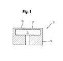
- a measuring device shown which is used in a combined pressure and temperature sensor, comprises a sensor element 11 with a rigid frame 13, in which a fluid chamber 15 is formed.
- a fluid to be measured in particular a liquid and / or a gas, located in the fluid chamber 15.
- the other side of the membrane 17, which faces away from the fluid is exposed to a reference pressure, in particular the ambient pressure or hydrostatic pressure of the atmosphere surrounding the sensor.
- the membrane 17 may be formed integrally or separately from the frame 13.
- the sensor element 11 has on the side facing away from the fluid chamber 15 of the membrane 17 on a flat surface 19 on which thin layers are deposited, as explained in more detail below.
- the measuring device is housed in a housing, not shown, which in the direction of an open side of the fluid chamber 15 has a functional connection has, for example, a thread with which the sensor can be coupled to a fluid housing, not shown.
- the membrane 17 is mechanically deflected or deformed.
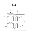
- U 0 is the supply voltage of the measuring bridge 21.
- the measuring bridge 21, together with the sensor element 11, forms a pressure transducer.
- the resistance elements R1-R4 are pressure-dependent resistance elements, ie a change in the fluid pressure leads to a corresponding change in the resistance value of the respective resistance element R1-R4.
- the resistance elements R1-R4 are each designed as strain gauges and applied in thin-film technology, in particular by means of PVD and / or CVD, on the flat surface 19 of the sensor element 11, in particular on the membrane 17.
- the resistive elements R1-R4 were applied with a single, common deposition, ie they are all made of the same material, which furthermore has no temperature dependence, for example titanium oxynitride.
- the resistance elements R1-R4 are in particular so shaped and / or arranged on the membrane 17, that with increasing pressure difference across the membrane 17, the electrical resistance of the two in the equivalent circuit of the measuring bridge 21 diagonally opposite resistance elements R1 and R4, for example, decreases, while the electrical resistance of the two in the equivalent circuit of the measuring bridge 21 diagonally opposite resistance elements R2 and R3 increases, or vice versa. In principle, however, it is sufficient if only one, two or three of the resistance elements R1-R4 are pressure-dependent. Non-pressure dependent resistive elements may e.g. be generated by appropriate geometric shape or arrangement or by separate deposition with another material.
- the measuring bridge 23 forms, together with the sensor element 11, a temperature transducer which operates independently of the pressure transducer.
- the further resistance element R15 is temperature-dependent.
- the further resistive element R15 was applied to the sensor element 11 by means of a further deposition separate from the abovementioned deposition and consists of a temperature-dependent material which is different from the material of the resistive elements R1-R4, for example of a nickel layer.
- the further resistance element R15 already has no pressure dependence due to the material used for this purpose and, moreover, is not applied on the membrane 17 but on its outside, on the frame 13 which is not subject to deformation.
- the further resistance element R 16 has already been applied to the membrane 17 together with the resistance elements R 1 -R 4, i. the further resistive element R16 is made of the same material as the resistive elements R1-R4 and is temperature independent.
- the shape and arrangement of the further resistance element R16 is chosen such that it - in contrast to the resistance elements R1-R4 - has no pressure dependence.
- the resistance elements R1-R4 and R16 can basically also be deposited only after the resistance element R15.
- At least two layers are deposited in succession for the pressure measurement and for the temperature measurement, each of which is patterned, for example by means of photolithographic processes, in such a way that electrical resistances are formed and interconnected, which are separate pressure- or temperature-dependent.
- the individual layers each have, in particular, a thickness or height of at most 3 ⁇ m, preferably at most 1 ⁇ m, and an electrical resistance in the range from 0.1 kohm to 50 kohm, preferably in the range from 0.5 kohm to 10 kohm, per resistor on.
- Such a layer may in each case also be a multi-layer, in which case at least one layer is formed as a functional layer.
- the layers for the pressure measurement and the temperature measurement are different from each other in at least one layer in their material composition.
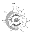
- Fig. 3 the two measuring bridges 21, 23 are shown according to an exemplary layout or in a plan view.
- the circular extent of the membrane 17, which is circular in the case shown, is shown by dashed lines.
- the resistance elements R1-R4, R15 and R16 of the two measuring bridges 21, 23 are provided for electrical contacting with terminals in the form of bonding pads 25.
- the terminals 25 were deposited together with the further resistance element R 15.
- the present invention describes the integration of a pressure transducer and a temperature transmitter, both of which are manufactured in the same technology, namely thin-film technology. This allows an overall cost-effective production.
Landscapes
- Physics & Mathematics (AREA)
- General Physics & Mathematics (AREA)
- Chemical & Material Sciences (AREA)
- Analytical Chemistry (AREA)
- Measuring Fluid Pressure (AREA)
Applications Claiming Priority (1)
| Application Number | Priority Date | Filing Date | Title |
|---|---|---|---|
| DE102011109461.3A DE102011109461B4 (de) | 2011-08-04 | 2011-08-04 | Druck- und Temperaturmessvorrichtung |
Publications (4)
| Publication Number | Publication Date |
|---|---|
| EP2554964A2 true EP2554964A2 (fr) | 2013-02-06 |
| EP2554964A3 EP2554964A3 (fr) | 2014-10-01 |
| EP2554964B1 EP2554964B1 (fr) | 2016-04-13 |
| EP2554964B2 EP2554964B2 (fr) | 2021-03-10 |
Family
ID=46506212
Family Applications (1)
| Application Number | Title | Priority Date | Filing Date |
|---|---|---|---|
| EP12175538.3A Active EP2554964B2 (fr) | 2011-08-04 | 2012-07-09 | Dispositif de mesure de la pression et de la température |
Country Status (2)
| Country | Link |
|---|---|
| EP (1) | EP2554964B2 (fr) |
| DE (1) | DE102011109461B4 (fr) |
Cited By (3)
| Publication number | Priority date | Publication date | Assignee | Title |
|---|---|---|---|---|
| CN104819798A (zh) * | 2015-05-08 | 2015-08-05 | 西南科技大学 | 一种在线监测尾矿淋滤实验水压变化传感器 |
| DE102018106518A1 (de) * | 2018-03-20 | 2019-09-26 | Tdk Electronics Ag | Sensorelement zur Druck- und Temperaturmessung |
| CN113360025A (zh) * | 2021-06-23 | 2021-09-07 | 维沃移动通信有限公司 | 电子设备 |
Families Citing this family (3)
| Publication number | Priority date | Publication date | Assignee | Title |
|---|---|---|---|---|
| DE102018121294A1 (de) * | 2018-08-31 | 2020-03-05 | Trafag Ag | Verfahren zur Herstellung eines Sensorelements mit mehreren Funktionsschichten für einen Drucksensor, Sensorelement und Sensor |
| CN116420062A (zh) * | 2020-10-20 | 2023-07-11 | 伊格尔工业股份有限公司 | 压力温度传感器 |
| DE102024122795B3 (de) * | 2024-08-09 | 2025-10-30 | Tdk Electronics Ag | Widerstandslayout für Drucksensor |
Citations (1)
| Publication number | Priority date | Publication date | Assignee | Title |
|---|---|---|---|---|
| DE102010012823A1 (de) | 2009-12-11 | 2011-06-16 | Armaturenbau Gmbh | Druckmittler mit Temperatursensor |
Family Cites Families (16)
| Publication number | Priority date | Publication date | Assignee | Title |
|---|---|---|---|---|
| US2738678A (en) * | 1952-10-21 | 1956-03-20 | Leeds & Northrup Co | Liquid manometers |
| US4320664A (en) | 1980-02-25 | 1982-03-23 | Texas Instruments Incorporated | Thermally compensated silicon pressure sensor |
| DE9209083U1 (de) * | 1991-07-20 | 1992-09-24 | Tubbesing, Dietmar, Dipl.-Ing., 5760 Arnsberg | Temperaturmeßgerät |
| US5343755A (en) * | 1993-05-05 | 1994-09-06 | Rosemount Inc. | Strain gage sensor with integral temperature signal |
| DE4415984A1 (de) * | 1994-05-06 | 1995-11-09 | Bosch Gmbh Robert | Halbleitersensor mit Schutzschicht |
| SE9600334D0 (sv) * | 1996-01-30 | 1996-01-30 | Radi Medical Systems | Combined flow, pressure and temperature sensor |
| JP3107516B2 (ja) | 1996-05-01 | 2000-11-13 | 株式会社日立製作所 | 複合センサ |
| JPH10170370A (ja) * | 1996-12-10 | 1998-06-26 | Nok Corp | 圧力センサ |
| US6612175B1 (en) * | 2000-07-20 | 2003-09-02 | Nt International, Inc. | Sensor usable in ultra pure and highly corrosive environments |
| GB2370122B (en) | 2000-12-16 | 2005-04-27 | Senstronics Ltd | Temperature compensated strain gauge |
| EP1281947A1 (fr) | 2001-08-03 | 2003-02-05 | Trafag AG | Capteur à haute pression et procédé pour la fabrication |
| DE10304024B4 (de) * | 2002-02-15 | 2015-08-20 | Continental Teves Ag & Co. Ohg | Verfahren und Schaltungsanordnung zur Überprüfung einer Drucksensoranordnung |
| DE102005015335A1 (de) * | 2005-04-01 | 2006-10-05 | Suss Microtec Test Systems Gmbh | Druckprober zur partiellen, berührungslosen Druckmessung von Drucksensoren |
| DE102006007463B3 (de) * | 2006-02-17 | 2007-06-21 | Jumo Gmbh & Co. Kg | Brückenschaltung und Verfahren zum Abgleichen einer Brückenschaltung |
| DE102006047481B4 (de) * | 2006-04-26 | 2023-02-09 | Fritsch Gmbh | Planeten- oder Fliehkraftkugelmühle im Labormaßstab mit Druck- und Temperaturerfassung |
| JP2008039760A (ja) * | 2006-07-14 | 2008-02-21 | Denso Corp | 圧力センサ |
-
2011
- 2011-08-04 DE DE102011109461.3A patent/DE102011109461B4/de active Active
-
2012
- 2012-07-09 EP EP12175538.3A patent/EP2554964B2/fr active Active
Patent Citations (1)
| Publication number | Priority date | Publication date | Assignee | Title |
|---|---|---|---|---|
| DE102010012823A1 (de) | 2009-12-11 | 2011-06-16 | Armaturenbau Gmbh | Druckmittler mit Temperatursensor |
Cited By (8)
| Publication number | Priority date | Publication date | Assignee | Title |
|---|---|---|---|---|
| CN104819798A (zh) * | 2015-05-08 | 2015-08-05 | 西南科技大学 | 一种在线监测尾矿淋滤实验水压变化传感器 |
| DE102018106518A1 (de) * | 2018-03-20 | 2019-09-26 | Tdk Electronics Ag | Sensorelement zur Druck- und Temperaturmessung |
| WO2019180018A1 (fr) * | 2018-03-20 | 2019-09-26 | Tdk Electronics Ag | Élément sensible pour mesurer la pression et la température |
| CN111886486A (zh) * | 2018-03-20 | 2020-11-03 | Tdk电子股份有限公司 | 用于压力测量和温度测量的传感元件 |
| JP2021516761A (ja) * | 2018-03-20 | 2021-07-08 | ティーディーケイ・エレクトロニクス・アクチェンゲゼルシャフトTdk Electronics Ag | 圧力及び温度測定用のセンサ素子 |
| CN111886486B (zh) * | 2018-03-20 | 2022-04-08 | Tdk电子股份有限公司 | 用于压力测量和温度测量的传感元件 |
| CN113360025A (zh) * | 2021-06-23 | 2021-09-07 | 维沃移动通信有限公司 | 电子设备 |
| CN113360025B (zh) * | 2021-06-23 | 2023-08-22 | 维沃移动通信有限公司 | 电子设备 |
Also Published As
| Publication number | Publication date |
|---|---|
| EP2554964A3 (fr) | 2014-10-01 |
| DE102011109461B4 (de) | 2025-01-16 |
| EP2554964B2 (fr) | 2021-03-10 |
| DE102011109461A1 (de) | 2013-02-07 |
| EP2554964B1 (fr) | 2016-04-13 |
Similar Documents
| Publication | Publication Date | Title |
|---|---|---|
| DE69210041T2 (de) | Entwurf von piezoresistivem drucksensor aus silizium | |
| EP2554964B1 (fr) | Dispositif de mesure de la pression et de la température | |
| DE69308512T2 (de) | Piezoelektrischer Antrieb mit Dehnungsmesser | |
| EP1640696B1 (fr) | Capteur de pression | |
| DE3703697A1 (de) | Drucksensor | |
| DE60025355T2 (de) | Dehnungsmessstreifen | |
| DE10256376A1 (de) | Massendurchflußmeßgerät und Verfahren zur Druckmessung bei einem Massendurchflußmeßgerät | |
| WO2015039810A1 (fr) | Convertisseur de mesure de pression | |
| DE112018008166T5 (de) | Mehrachsiger tastsensor | |
| DE102018203251B4 (de) | Messen von mechanischen Veränderungen | |
| DE102017223831A1 (de) | Dehnungsstreifen umfassend ein flexibles Substrat sowie eine Widerstandsschicht und Sensorelement umfassend einen Dehnungsmessstreifen | |
| DE102009024576A1 (de) | Differenzdrucksensor | |
| EP2543979A2 (fr) | Transducteur de pression | |
| DE102020100675B4 (de) | Kapazitiver Drucksensor mit Temperaturerfassung | |
| DE3042506C2 (de) | Dehnungsmeßstreifenwandler | |
| DE102010012701A1 (de) | Mikrokraftsensor | |
| DE102010024806B4 (de) | Drehmoment-Messeinrichtung und Verfahren zur Drehmomentmessung | |
| DE102019102908A1 (de) | Sensorvorrichtung für Druckmessungen von Fluiden, System für Druckmessungen von Fluiden | |
| EP3935361B1 (fr) | Porcédè pour contrôler un arrangement decapteur de pression | |
| DE112022004345T5 (de) | Drucksensor | |
| DE102008055774B4 (de) | Vorrichtung zum Messen einer Temperatur eines Bauteils und Vorrichtung zum Messen einer Dehnung eines Bauteils | |
| WO2016016026A1 (fr) | Capteur de pression et procédé de fabrication d'un capteur de pression | |
| DE102011006922B4 (de) | Messwandler für die Sensortechnik | |
| DE2825489A1 (de) | Verfahren zur herstellung einer spannvorrichtung | |
| EP4194830B1 (fr) | Capteur de force résistif et capacitif et procédé de fonctionnement de celui-ci |
Legal Events
| Date | Code | Title | Description |
|---|---|---|---|
| PUAI | Public reference made under article 153(3) epc to a published international application that has entered the european phase |
Free format text: ORIGINAL CODE: 0009012 |
|
| AK | Designated contracting states |
Kind code of ref document: A2 Designated state(s): AL AT BE BG CH CY CZ DE DK EE ES FI FR GB GR HR HU IE IS IT LI LT LU LV MC MK MT NL NO PL PT RO RS SE SI SK SM TR |
|
| AX | Request for extension of the european patent |
Extension state: BA ME |
|
| PUAL | Search report despatched |
Free format text: ORIGINAL CODE: 0009013 |
|
| AK | Designated contracting states |
Kind code of ref document: A3 Designated state(s): AL AT BE BG CH CY CZ DE DK EE ES FI FR GB GR HR HU IE IS IT LI LT LU LV MC MK MT NL NO PL PT RO RS SE SI SK SM TR |
|
| AX | Request for extension of the european patent |
Extension state: BA ME |
|
| RIC1 | Information provided on ipc code assigned before grant |
Ipc: G01L 19/00 20060101ALI20140825BHEP Ipc: G01L 9/00 20060101AFI20140825BHEP Ipc: G01L 19/04 20060101ALI20140825BHEP |
|
| 17P | Request for examination filed |
Effective date: 20150331 |
|
| RBV | Designated contracting states (corrected) |
Designated state(s): AL AT BE BG CH CY CZ DE DK EE ES FI FR GB GR HR HU IE IS IT LI LT LU LV MC MK MT NL NO PL PT RO RS SE SI SK SM TR |
|
| 17Q | First examination report despatched |
Effective date: 20150619 |
|
| REG | Reference to a national code |
Ref country code: DE Ref legal event code: R079 Ref document number: 502012006694 Country of ref document: DE Free format text: PREVIOUS MAIN CLASS: G01L0009000000 Ipc: G01K0007200000 |
|
| GRAP | Despatch of communication of intention to grant a patent |
Free format text: ORIGINAL CODE: EPIDOSNIGR1 |
|
| RIC1 | Information provided on ipc code assigned before grant |
Ipc: G01L 19/00 20060101ALI20151001BHEP Ipc: G01L 9/00 20060101ALI20151001BHEP Ipc: G01K 7/20 20060101AFI20151001BHEP |
|
| INTG | Intention to grant announced |
Effective date: 20151028 |
|
| GRAS | Grant fee paid |
Free format text: ORIGINAL CODE: EPIDOSNIGR3 |
|
| GRAA | (expected) grant |
Free format text: ORIGINAL CODE: 0009210 |
|
| AK | Designated contracting states |
Kind code of ref document: B1 Designated state(s): AL AT BE BG CH CY CZ DE DK EE ES FI FR GB GR HR HU IE IS IT LI LT LU LV MC MK MT NL NO PL PT RO RS SE SI SK SM TR |
|
| REG | Reference to a national code |
Ref country code: GB Ref legal event code: FG4D Free format text: NOT ENGLISH |
|
| REG | Reference to a national code |
Ref country code: AT Ref legal event code: REF Ref document number: 790637 Country of ref document: AT Kind code of ref document: T Effective date: 20160415 Ref country code: CH Ref legal event code: EP Ref country code: CH Ref legal event code: NV Representative=s name: INTELLECTUAL PROPERTY SERVICES GMBH, CH |
|
| REG | Reference to a national code |
Ref country code: IE Ref legal event code: FG4D Free format text: LANGUAGE OF EP DOCUMENT: GERMAN |
|
| REG | Reference to a national code |
Ref country code: DE Ref legal event code: R096 Ref document number: 502012006694 Country of ref document: DE |
|
| REG | Reference to a national code |
Ref country code: FR Ref legal event code: PLFP Year of fee payment: 5 |
|
| REG | Reference to a national code |
Ref country code: LT Ref legal event code: MG4D |
|
| REG | Reference to a national code |
Ref country code: NL Ref legal event code: MP Effective date: 20160413 |
|
| PG25 | Lapsed in a contracting state [announced via postgrant information from national office to epo] |
Ref country code: FI Free format text: LAPSE BECAUSE OF FAILURE TO SUBMIT A TRANSLATION OF THE DESCRIPTION OR TO PAY THE FEE WITHIN THE PRESCRIBED TIME-LIMIT Effective date: 20160413 Ref country code: NL Free format text: LAPSE BECAUSE OF FAILURE TO SUBMIT A TRANSLATION OF THE DESCRIPTION OR TO PAY THE FEE WITHIN THE PRESCRIBED TIME-LIMIT Effective date: 20160413 Ref country code: NO Free format text: LAPSE BECAUSE OF FAILURE TO SUBMIT A TRANSLATION OF THE DESCRIPTION OR TO PAY THE FEE WITHIN THE PRESCRIBED TIME-LIMIT Effective date: 20160713 Ref country code: PL Free format text: LAPSE BECAUSE OF FAILURE TO SUBMIT A TRANSLATION OF THE DESCRIPTION OR TO PAY THE FEE WITHIN THE PRESCRIBED TIME-LIMIT Effective date: 20160413 Ref country code: LT Free format text: LAPSE BECAUSE OF FAILURE TO SUBMIT A TRANSLATION OF THE DESCRIPTION OR TO PAY THE FEE WITHIN THE PRESCRIBED TIME-LIMIT Effective date: 20160413 |
|
| PGFP | Annual fee paid to national office [announced via postgrant information from national office to epo] |
Ref country code: CH Payment date: 20160721 Year of fee payment: 5 |
|
| PG25 | Lapsed in a contracting state [announced via postgrant information from national office to epo] |
Ref country code: SE Free format text: LAPSE BECAUSE OF FAILURE TO SUBMIT A TRANSLATION OF THE DESCRIPTION OR TO PAY THE FEE WITHIN THE PRESCRIBED TIME-LIMIT Effective date: 20160413 Ref country code: ES Free format text: LAPSE BECAUSE OF FAILURE TO SUBMIT A TRANSLATION OF THE DESCRIPTION OR TO PAY THE FEE WITHIN THE PRESCRIBED TIME-LIMIT Effective date: 20160413 Ref country code: RS Free format text: LAPSE BECAUSE OF FAILURE TO SUBMIT A TRANSLATION OF THE DESCRIPTION OR TO PAY THE FEE WITHIN THE PRESCRIBED TIME-LIMIT Effective date: 20160413 Ref country code: GR Free format text: LAPSE BECAUSE OF FAILURE TO SUBMIT A TRANSLATION OF THE DESCRIPTION OR TO PAY THE FEE WITHIN THE PRESCRIBED TIME-LIMIT Effective date: 20160714 Ref country code: LV Free format text: LAPSE BECAUSE OF FAILURE TO SUBMIT A TRANSLATION OF THE DESCRIPTION OR TO PAY THE FEE WITHIN THE PRESCRIBED TIME-LIMIT Effective date: 20160413 Ref country code: HR Free format text: LAPSE BECAUSE OF FAILURE TO SUBMIT A TRANSLATION OF THE DESCRIPTION OR TO PAY THE FEE WITHIN THE PRESCRIBED TIME-LIMIT Effective date: 20160413 Ref country code: PT Free format text: LAPSE BECAUSE OF FAILURE TO SUBMIT A TRANSLATION OF THE DESCRIPTION OR TO PAY THE FEE WITHIN THE PRESCRIBED TIME-LIMIT Effective date: 20160816 |
|
| PGFP | Annual fee paid to national office [announced via postgrant information from national office to epo] |
Ref country code: FR Payment date: 20160721 Year of fee payment: 5 |
|
| PG25 | Lapsed in a contracting state [announced via postgrant information from national office to epo] |
Ref country code: IT Free format text: LAPSE BECAUSE OF FAILURE TO SUBMIT A TRANSLATION OF THE DESCRIPTION OR TO PAY THE FEE WITHIN THE PRESCRIBED TIME-LIMIT Effective date: 20160413 Ref country code: BE Free format text: LAPSE BECAUSE OF NON-PAYMENT OF DUE FEES Effective date: 20160731 |
|
| REG | Reference to a national code |
Ref country code: DE Ref legal event code: R026 Ref document number: 502012006694 Country of ref document: DE |
|
| PLBI | Opposition filed |
Free format text: ORIGINAL CODE: 0009260 |
|
| PLBI | Opposition filed |
Free format text: ORIGINAL CODE: 0009260 |
|
| PG25 | Lapsed in a contracting state [announced via postgrant information from national office to epo] |
Ref country code: EE Free format text: LAPSE BECAUSE OF FAILURE TO SUBMIT A TRANSLATION OF THE DESCRIPTION OR TO PAY THE FEE WITHIN THE PRESCRIBED TIME-LIMIT Effective date: 20160413 Ref country code: RO Free format text: LAPSE BECAUSE OF FAILURE TO SUBMIT A TRANSLATION OF THE DESCRIPTION OR TO PAY THE FEE WITHIN THE PRESCRIBED TIME-LIMIT Effective date: 20160413 Ref country code: SK Free format text: LAPSE BECAUSE OF FAILURE TO SUBMIT A TRANSLATION OF THE DESCRIPTION OR TO PAY THE FEE WITHIN THE PRESCRIBED TIME-LIMIT Effective date: 20160413 Ref country code: DK Free format text: LAPSE BECAUSE OF FAILURE TO SUBMIT A TRANSLATION OF THE DESCRIPTION OR TO PAY THE FEE WITHIN THE PRESCRIBED TIME-LIMIT Effective date: 20160413 Ref country code: CZ Free format text: LAPSE BECAUSE OF FAILURE TO SUBMIT A TRANSLATION OF THE DESCRIPTION OR TO PAY THE FEE WITHIN THE PRESCRIBED TIME-LIMIT Effective date: 20160413 |
|
| 26 | Opposition filed |
Opponent name: SENSTRONICS LIMITED Effective date: 20161230 |
|
| 26 | Opposition filed |
Opponent name: TRAFAG AG Effective date: 20170113 |
|
| PLAX | Notice of opposition and request to file observation + time limit sent |
Free format text: ORIGINAL CODE: EPIDOSNOBS2 |
|
| PG25 | Lapsed in a contracting state [announced via postgrant information from national office to epo] |
Ref country code: SM Free format text: LAPSE BECAUSE OF FAILURE TO SUBMIT A TRANSLATION OF THE DESCRIPTION OR TO PAY THE FEE WITHIN THE PRESCRIBED TIME-LIMIT Effective date: 20160413 |
|
| PG25 | Lapsed in a contracting state [announced via postgrant information from national office to epo] |
Ref country code: MC Free format text: LAPSE BECAUSE OF FAILURE TO SUBMIT A TRANSLATION OF THE DESCRIPTION OR TO PAY THE FEE WITHIN THE PRESCRIBED TIME-LIMIT Effective date: 20160413 |
|
| REG | Reference to a national code |
Ref country code: IE Ref legal event code: MM4A |
|
| PG25 | Lapsed in a contracting state [announced via postgrant information from national office to epo] |
Ref country code: SI Free format text: LAPSE BECAUSE OF FAILURE TO SUBMIT A TRANSLATION OF THE DESCRIPTION OR TO PAY THE FEE WITHIN THE PRESCRIBED TIME-LIMIT Effective date: 20160413 |
|
| RAP2 | Party data changed (patent owner data changed or rights of a patent transferred) |
Owner name: SENSATA GERMANY GMBH |
|
| PLBB | Reply of patent proprietor to notice(s) of opposition received |
Free format text: ORIGINAL CODE: EPIDOSNOBS3 |
|
| PG25 | Lapsed in a contracting state [announced via postgrant information from national office to epo] |
Ref country code: IE Free format text: LAPSE BECAUSE OF NON-PAYMENT OF DUE FEES Effective date: 20160709 |
|
| PG25 | Lapsed in a contracting state [announced via postgrant information from national office to epo] |
Ref country code: LU Free format text: LAPSE BECAUSE OF NON-PAYMENT OF DUE FEES Effective date: 20160709 |
|
| REG | Reference to a national code |
Ref country code: CH Ref legal event code: PL |
|
| REG | Reference to a national code |
Ref country code: FR Ref legal event code: ST Effective date: 20180330 |
|
| PG25 | Lapsed in a contracting state [announced via postgrant information from national office to epo] |
Ref country code: LI Free format text: LAPSE BECAUSE OF NON-PAYMENT OF DUE FEES Effective date: 20170731 Ref country code: CH Free format text: LAPSE BECAUSE OF NON-PAYMENT OF DUE FEES Effective date: 20170731 |
|
| PG25 | Lapsed in a contracting state [announced via postgrant information from national office to epo] |
Ref country code: FR Free format text: LAPSE BECAUSE OF NON-PAYMENT OF DUE FEES Effective date: 20170731 Ref country code: HU Free format text: LAPSE BECAUSE OF FAILURE TO SUBMIT A TRANSLATION OF THE DESCRIPTION OR TO PAY THE FEE WITHIN THE PRESCRIBED TIME-LIMIT; INVALID AB INITIO Effective date: 20120709 Ref country code: CY Free format text: LAPSE BECAUSE OF FAILURE TO SUBMIT A TRANSLATION OF THE DESCRIPTION OR TO PAY THE FEE WITHIN THE PRESCRIBED TIME-LIMIT Effective date: 20160413 |
|
| PG25 | Lapsed in a contracting state [announced via postgrant information from national office to epo] |
Ref country code: MK Free format text: LAPSE BECAUSE OF FAILURE TO SUBMIT A TRANSLATION OF THE DESCRIPTION OR TO PAY THE FEE WITHIN THE PRESCRIBED TIME-LIMIT Effective date: 20160413 Ref country code: IS Free format text: LAPSE BECAUSE OF FAILURE TO SUBMIT A TRANSLATION OF THE DESCRIPTION OR TO PAY THE FEE WITHIN THE PRESCRIBED TIME-LIMIT Effective date: 20160413 Ref country code: MT Free format text: LAPSE BECAUSE OF FAILURE TO SUBMIT A TRANSLATION OF THE DESCRIPTION OR TO PAY THE FEE WITHIN THE PRESCRIBED TIME-LIMIT Effective date: 20160413 Ref country code: TR Free format text: LAPSE BECAUSE OF FAILURE TO SUBMIT A TRANSLATION OF THE DESCRIPTION OR TO PAY THE FEE WITHIN THE PRESCRIBED TIME-LIMIT Effective date: 20160413 |
|
| PG25 | Lapsed in a contracting state [announced via postgrant information from national office to epo] |
Ref country code: BG Free format text: LAPSE BECAUSE OF FAILURE TO SUBMIT A TRANSLATION OF THE DESCRIPTION OR TO PAY THE FEE WITHIN THE PRESCRIBED TIME-LIMIT Effective date: 20160413 |
|
| REG | Reference to a national code |
Ref country code: AT Ref legal event code: MM01 Ref document number: 790637 Country of ref document: AT Kind code of ref document: T Effective date: 20170709 |
|
| PG25 | Lapsed in a contracting state [announced via postgrant information from national office to epo] |
Ref country code: AL Free format text: LAPSE BECAUSE OF FAILURE TO SUBMIT A TRANSLATION OF THE DESCRIPTION OR TO PAY THE FEE WITHIN THE PRESCRIBED TIME-LIMIT Effective date: 20160413 |
|
| PG25 | Lapsed in a contracting state [announced via postgrant information from national office to epo] |
Ref country code: AT Free format text: LAPSE BECAUSE OF NON-PAYMENT OF DUE FEES Effective date: 20170709 |
|
| PLAY | Examination report in opposition despatched + time limit |
Free format text: ORIGINAL CODE: EPIDOSNORE2 |
|
| PLBC | Reply to examination report in opposition received |
Free format text: ORIGINAL CODE: EPIDOSNORE3 |
|
| APBM | Appeal reference recorded |
Free format text: ORIGINAL CODE: EPIDOSNREFNO |
|
| APBP | Date of receipt of notice of appeal recorded |
Free format text: ORIGINAL CODE: EPIDOSNNOA2O |
|
| APAH | Appeal reference modified |
Free format text: ORIGINAL CODE: EPIDOSCREFNO |
|
| APBM | Appeal reference recorded |
Free format text: ORIGINAL CODE: EPIDOSNREFNO |
|
| APBP | Date of receipt of notice of appeal recorded |
Free format text: ORIGINAL CODE: EPIDOSNNOA2O |
|
| APBQ | Date of receipt of statement of grounds of appeal recorded |
Free format text: ORIGINAL CODE: EPIDOSNNOA3O |
|
| APBQ | Date of receipt of statement of grounds of appeal recorded |
Free format text: ORIGINAL CODE: EPIDOSNNOA3O |
|
| APBU | Appeal procedure closed |
Free format text: ORIGINAL CODE: EPIDOSNNOA9O |
|
| PUAH | Patent maintained in amended form |
Free format text: ORIGINAL CODE: 0009272 |
|
| STAA | Information on the status of an ep patent application or granted ep patent |
Free format text: STATUS: PATENT MAINTAINED AS AMENDED |
|
| 27A | Patent maintained in amended form |
Effective date: 20210310 |
|
| AK | Designated contracting states |
Kind code of ref document: B2 Designated state(s): AL AT BE BG CH CY CZ DE DK EE ES FI FR GB GR HR HU IE IS IT LI LT LU LV MC MK MT NL NO PL PT RO RS SE SI SK SM TR |
|
| REG | Reference to a national code |
Ref country code: DE Ref legal event code: R102 Ref document number: 502012006694 Country of ref document: DE |
|
| P01 | Opt-out of the competence of the unified patent court (upc) registered |
Effective date: 20230708 |
|
| PGFP | Annual fee paid to national office [announced via postgrant information from national office to epo] |
Ref country code: DE Payment date: 20250729 Year of fee payment: 14 |
|
| PGFP | Annual fee paid to national office [announced via postgrant information from national office to epo] |
Ref country code: GB Payment date: 20250728 Year of fee payment: 14 |