EP2554968A1 - Sensorsystem zur Messung des Differenzdrucks - Google Patents
Sensorsystem zur Messung des Differenzdrucks Download PDFInfo
- Publication number
- EP2554968A1 EP2554968A1 EP11176135A EP11176135A EP2554968A1 EP 2554968 A1 EP2554968 A1 EP 2554968A1 EP 11176135 A EP11176135 A EP 11176135A EP 11176135 A EP11176135 A EP 11176135A EP 2554968 A1 EP2554968 A1 EP 2554968A1
- Authority
- EP
- European Patent Office
- Prior art keywords
- carrier element
- sensing element
- sensor system
- electronics module
- housing assembly
- Prior art date
- Legal status (The legal status is an assumption and is not a legal conclusion. Google has not performed a legal analysis and makes no representation as to the accuracy of the status listed.)
- Granted
Links
Images

Classifications
-
- G—PHYSICS
- G01—MEASURING; TESTING
- G01L—MEASURING FORCE, STRESS, TORQUE, WORK, MECHANICAL POWER, MECHANICAL EFFICIENCY, OR FLUID PRESSURE
- G01L19/00—Details of, or accessories for, apparatus for measuring steady or quasi-steady pressure of a fluent medium insofar as such details or accessories are not special to particular types of pressure gauges
- G01L19/06—Means for preventing overload or deleterious influence of the measured medium on the measuring device or vice versa
-
- G—PHYSICS
- G01—MEASURING; TESTING
- G01L—MEASURING FORCE, STRESS, TORQUE, WORK, MECHANICAL POWER, MECHANICAL EFFICIENCY, OR FLUID PRESSURE
- G01L19/00—Details of, or accessories for, apparatus for measuring steady or quasi-steady pressure of a fluent medium insofar as such details or accessories are not special to particular types of pressure gauges
- G01L19/14—Housings
-
- F—MECHANICAL ENGINEERING; LIGHTING; HEATING; WEAPONS; BLASTING
- F01—MACHINES OR ENGINES IN GENERAL; ENGINE PLANTS IN GENERAL; STEAM ENGINES
- F01N—GAS-FLOW SILENCERS OR EXHAUST APPARATUS FOR MACHINES OR ENGINES IN GENERAL; GAS-FLOW SILENCERS OR EXHAUST APPARATUS FOR INTERNAL-COMBUSTION ENGINES
- F01N11/00—Monitoring or diagnostic devices for exhaust-gas treatment apparatus
-
- G—PHYSICS
- G01—MEASURING; TESTING
- G01L—MEASURING FORCE, STRESS, TORQUE, WORK, MECHANICAL POWER, MECHANICAL EFFICIENCY, OR FLUID PRESSURE
- G01L13/00—Devices or apparatus for measuring differences of two or more fluid pressure values
Definitions
- the present invention relates to a sensor system for measuring pressure in an exhaust conduit of a combustion engine, the sensor system comprising an electronics module assembly and a housing assembly for housing the electronics module assembly.
- European patent application EP-A-1 521 952 discloses a pressure measuring device.
- the device is provided with two housing parts, of which one can be implemented as cover part.
- a single carrier is provided on which a (pressure) sensing element is positioned, and on which also electronic components may be positioned.
- the housing internally comprises three housing spaces, which are separated from each other using seals.
- the first and third housing spaces are in communication with a front and a back side of the sensing element, respectively.
- the second space accommodates bonding wires from the single carrier to contact elements of a connector integrated with the housing.
- European patent application EP-A-2 184 594 discloses a pressure sensor for measuring pressure in a medium, comprising a sensor housing, and a support member on which a sensing element and further electronic components are positioned.
- the sensing element front and back side are protected from the environment (i.e. the medium) using a gel like protective member.
- the protective member is only provided in an area surrounding the sensing element, using barriers attached to the support member.
- the present invention seeks to provide an improved sensor system, especially suited for automotive applications such as exhaust gas measurement.
- a sensor system according to the preamble defined above is provided, wherein the electronics module assembly comprises a sensing element carrier element with a sensing element, an electronics module carrier element carrying electronic components, wherein electrical connections are provided between the electronic module carrier element and the sensing element carrier element, and a main carrier element for supporting the sensing element carrier element and the electronic module carrier element.
- the sensing element carrier element comprises a ceramic substrate, and/or the electronics module carrier element is a printed circuit board. Furthermore, the sensing element carrier element and electronics module carrier element may be connected using wire bonding. This allows efficient production of these elements as separate parts using the most efficient associated techniques.
- the main carrier element supports and mutually positions the sensing element carrier element and the electronics module carrier element. Also the main carrier element may be arranged for positioning of the electronics module assembly in the housing assembly.
- the sensor system further comprises a front side barrier attached to the sensing element carrier element and surrounding a top side of the sensing element, wherein the sensing element carrier element comprises conducting tracks, the conducting tracks within a space defined by the front side barrier being made of gold.
- the front side barrier may be used to accommodate a protective member, such as a gel, shielding the sensing element from e.g. exhaust gases during operation.
- the main carrier element is arranged as a back side barrier for a protective member covering the sensing element.
- the housing assembly comprises a high pressure connection and a low pressure connection at a bottom side of the housing assembly, wherein the electronic module assembly is connected to the high pressure connection via an adhesive bond onto the front side barrier and connected to the low pressure connection via an adhesive bond onto the main carrier element.
- the adhesive bond may act as a seal and may be provided onto a front side barrier which is attached to the sensing element carrier element and surrounds a top side of the sensing element and onto the main carrier element.
- a high pressure channel from the high pressure connection to the front side of the sensing element, and a low pressure channel from the low pressure connection to the back side of the sensing element may be provided with internal rounded edges to ensure unrestricted access to the sensing element without risk of clogging etc, e.g. due to moisture build up.
- a high pressure channel from the high pressure connection to the front side of the sensing element, and a low pressure channel from the low pressure connection to the back side of the sensing element may be provided, which comprise sloping walls having an inclination towards the bottom side of the housing assembly.
- the sensing element is positioned in a top part of the housing assembly, remote from the high pressure connection and the low pressure channel connection in a further embodiment.
- the main carrier element may be provided with a sloping wall for a similar effect.
- the electronics module assembly further comprises a front side barrier attached to the sensing element carrier element and surrounding a top side of the sensing element, the front side barrier being provided with a sealing rim and a de-watering edge at a bottom part of the front side barrier.
- the housing assembly comprises a housing assembly body, a first cover and a second cover, the first and second cover closing off a first and a second side of the housing assembly body, respectively.
- This allows production of the housing assembly body using e.g. well known and cost-effective injection moulding techniques, and easy assembly of the sensor system by adding the other elements and closing off the housing assembly body using the first and second cover.
- the first housing cover may be provided with a sloping wall which when assembled forms part of the low pressure channel.
- Pressure sensors such as differential pressure sensors
- the present invention embodiments relate to such a sensor system, and may be advantageously used for measuring pressure in an exhaust conduit of a combustion engine.
- the sensor system 1 comprises an electronics module assembly (EMA) 5 and a housing assembly 2-4 for housing the electronics module assembly 5.
- the housing assembly comprises a housing assembly body 2, a first cover 3 for covering a first side of the housing assembly body 2, and a second cover 4 for covering a second side of the housing assembly body 2.
- the sensor assembly is further provided with a high pressure connection 19 and a low pressure connection 20.
- Various parts of the sensor assembly 1 are attached to each other with seals in between, such as a seal 21 between the first cover 3 and the housing assembly body 2, a seal 22 between housing assembly body 2 and electronics module assembly 5, and a seal 23 between electronics module assembly 5 and second cover 4.
- the second cover 4 is furthermore attached to the housing assembly body 2 using an external seal 24.
- a housing assembly body 2 with two opposing opening faces which are closed off by the first and second cover 3, 4, allows to manufacture the housing assembly body with its internal features efficiently.
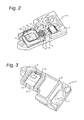
- Fig. 2 and 3 show a top and bottom view in perspective of an electronics module assembly 5 as used in an embodiment of the sensor system according to the present invention.
- the electronics module assembly 5 comprises a sensing element carrier element 8 (e.g. a ceramic board) with a sensing element 10, e.g. a MEMS pressure transducer.
- an electronics module carrier element 7 is provided carrying electronic components. Electrical connections 7a are provided between the electronic module carrier element 7 and the sensing element carrier element 8.
- a main carrier element 6 is provided for supporting the sensing element carrier element 8 and the electronic module carrier element 7.
- the sensing element carrier element 8 comprises a ceramic substrate and/or the electronics module carrier element 8 is a printed circuit board.
- the combination of main carrier element 6, electronics module carrier element 7 and sensing element carrier element 8, together forming the EMA 5, allows also to handle the EMA as a stand alone unit, e.g. allowing for calibration on the level of the EMA 5 in production.
- the sensing element carrier element 8 is provided with an opening 14, to allow using a differential pressure sensing element 10.
- the sensing element 10 is positioned in front of the opening 14, while sufficient sealing is provided to ensure no leakage from the front side of the sensing element 10 to the back side.
- the opening 14 in the sensing element carrier element 8 allows to have an integrated back side gel dam, allowing a bigger volume of gel to be applied on the back side of sensing element 10 (for protection against the exhaust gases).
- the sensing element carrier element 8 is in a further embodiment provided with a front side barrier 9 attached to the sensing element carrier element 8 and surrounding a top side of the sensing element 10. This allows providing a gel or other protective member on top of the sensing element 10, protecting it from the environment (such as diesel exhaust gases). Furthermore, the main carrier element 6 is arranged as a back side barrier for a protective member covering the sensing element 10 on the other side.
- the sensing element carrier element 8 comprises conducting tracks 17, 18.
- the conducting tracks 17 which are within a space defined by the front side barrier 9 are made of gold, which can resist the possible aggressive environment in that space.
- the further tracks 18, which runs outside of the front side barrier 9 can be made of less resistant material, such as AgPd.
- the conditioning electronics needed for the sensor system 1 can be easily integrated onto the electronics module carrier element (e.g. a PCB) 7 using standard manufacturing techniques.
- the sensing element carrier element 8 and electronics module carrier element 7 are connected using wire bonding, i.e. the electrical connections 7a are provided by wire bonds between bonding pads provided on each of the sensing element carrier element 8 and electronics module carrier element 7. This technique is widely used and can be applied very efficiently.
- the main carrier element 6 and the housing assembly 5 are made of plastic material suited for automotive applications.
- the main carrier element 6 supports and mutually positions the sensing element carrier element 8 and the electronics module carrier element 7, e.g. using guiding rims or other extensions. Furthermore, the main carrier element 6 positions of the electronics module assembly 5 in the housing assembly 2.
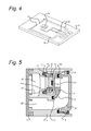
- Fig. 5 shows a cross sectional view of an embodiment of the sensor system 1 according to the present invention. It is clearly shown that the sensor housing comprises three parts, i.e. the sensor housing body 2, first cover 3 and second cover 4. The first and second cover 3, 4, close off the opposing open spaces of the housing assembly body 2. As shown in Fig. 5 , the various parts are provided with tongue and groove features, allowing a very good sealing of the various parts (using seals 21-23, see Fig. 1 as described above, and seal 31 between main carrier element 6 and the sensor housing body 2). Using such tongue and groove seals, the position and amount of sealant can be much better controlled.
- Stand offs and protrusions as these tongue and groove seals are also advantageous to control and minimize the variation of glue thickness for robustness of electronics module assembly 5 with the wire bond interconnects 7a.
- the environmental seal 24 for attaching the second cover 4 to the housing assembly body 2 is clearly shown.
- the first cover 3 is shown in position, i.e. in contact with the housing assembly body 2, but without the seal 21 (see Fig. 1 ).
- the electronic module assembly 5 is connected to the high pressure connection 19 and low pressure connection 20 via an adhesive bond (or sealant) onto the front side barrier 9 (seal 32 and rim 9) and the main carrier element 6 (seals 23, 31, and associated protrusions in main carrier element 6).
- the EMA 5 is shown in Fig. 5 in cross section where the sensing element carrier element 8 is attached to the main carrier element 6, i.e. where the sensing element 10 is positioned in front of the opening 14, and thus is in communication with a high pressure chamber (or channel 25) and a low pressure chamber (or channel) 26.
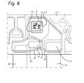
- Fig. 6 shows a side view of a part of the sensor system 1 according to a present invention embodiment, and shows that the high pressure chamber 25 is in communication with the high pressure connection 19, and that the low pressure chamber 26 is in communication with the low pressure connection 20 (see also Fig. 1 ).
- Prior art pressure sensors tend to be sensitive to possible build up of condensing fluid inside the pressure sensors. This can be the cause of malfunction of the sensor assembly 1, e.g. by resulting in a short circuit, corrosion or clogging (e.g. build up of ice under certain conditions).
- a number of technical features are provided which eliminate this problem to a high degree. It is noted that the features described herein to address the drainage improvements are related to gravity related features, i.e. the condensate build-up inside the sensor system 1 is able to flow out of the sensor system 1 after power down under the influence of gravity alone.
- the features can be applied stand alone as well, i.e. a sensor system 1 may be provided with the features now described in claims 8-15.
- the ability of a sensor system to quickly allow the fluid to flow out of the sensor system after power down is important to avoid loss of a sensor (pressure) signal in cold conditions, e.g. due to ice blocking the pressure tubes and chambers 25, 26. Furthermore, the sensor system 1 robustness against acidic exhaust gas environment is improved. When the water content of the exhaust condensate evaporates after power down of the engine, the pH values quickly drop to extreme low values. Self draining of the sensor system 1 takes care of removal of the condensate even before this can occur.
- the housing assembly comprises a high pressure connection 19 and a low pressure connection 20 at a bottom side of the housing assembly body 2, the high pressure connection 19 and the low pressure connection 20 having a sufficiently large inner diameter, e.g. of at least 5 mm.
- the high and low pressure channels are also as wide as possible, e.g. having a minimum cross sectional dimension of e.g. 5 mm.
- the housing assembly 2-4 provides a void of at least 5mm at the front and back side of the sensing element 10, when assembled.
- the high pressure chamber 25 from the high pressure connection 19 to the front side of the sensing element 10, and the low pressure chamber 26 from the low pressure connection 20 to the back side of the sensing element 10 are provided with internal rounded edges, e.g. having a curvature of at least 1 mm radius.
- the high and low pressure chambers 25, 26 inside the housing assembly body 2 may be provided with sloping walls 27-29, having an inclination towards the bottom side of the housing assembly body 2.
- the sloping walls 27, 28 are in the high pressure chamber 25, and the sloping wall 29 and rounded, sloping wall 30 (which is part of the second cover 4) are part of the low pressure chamber 26.
- the main carrier element 6 is provided with a sloping wall 12 (see Fig. 3 ) as part of the low pressure chamber 26, effectively routing condensate towards the low pressure connection 20.
- the sensing element 10 is furthermore positioned in a top part of the housing assembly body 2, remote from the high pressure connection 19 and the low pressure connection 20. This effectively helps in keeping any moisture or condensate away from the sensitive surface of the sensing element 10.
- the EMA 5 further comprising a front side barrier 9 attached to the sensing element carrier element 8 and surrounding a top side of the sensing element 10.
- the front side barrier 9 is provided with a sealing rim 11 (see also Fig. 2 ) and a de-watering edge 11 a at a bottom part of the front side barrier 9, i.e. the front side barrier 9 is asymmetric. This results in an upward edge having a width d1 in the high pressure chamber 25 from the housing assembly body 2 towards the sensing element carrier element 8, again increasing the resistance against moisture/condensate building up near the sensitive surface of the sensing element 10, and an easy pathway for the condensate towards the high pressure connection 19.
Landscapes
- Physics & Mathematics (AREA)
- General Physics & Mathematics (AREA)
- Engineering & Computer Science (AREA)
- Chemical & Material Sciences (AREA)
- Chemical Kinetics & Catalysis (AREA)
- Combustion & Propulsion (AREA)
- Mechanical Engineering (AREA)
- General Engineering & Computer Science (AREA)
- Measuring Fluid Pressure (AREA)
Priority Applications (5)
| Application Number | Priority Date | Filing Date | Title |
|---|---|---|---|
| EP11176135.9A EP2554968B1 (de) | 2011-08-01 | 2011-08-01 | Sensorsystem zur Messung des Differenzdrucks |
| JP2012163272A JP5955677B2 (ja) | 2011-08-01 | 2012-07-24 | 差圧力測定のためのセンサシステム |
| US13/561,170 US8707774B2 (en) | 2011-08-01 | 2012-07-30 | Sensor system for differential pressure measurement |
| KR1020120083989A KR101995073B1 (ko) | 2011-08-01 | 2012-07-31 | 차압 측정을 위한 센서 시스템 |
| CN201210271666.1A CN102914403B (zh) | 2011-08-01 | 2012-08-01 | 用于压差测量的传感器系统 |
Applications Claiming Priority (1)
| Application Number | Priority Date | Filing Date | Title |
|---|---|---|---|
| EP11176135.9A EP2554968B1 (de) | 2011-08-01 | 2011-08-01 | Sensorsystem zur Messung des Differenzdrucks |
Publications (2)
| Publication Number | Publication Date |
|---|---|
| EP2554968A1 true EP2554968A1 (de) | 2013-02-06 |
| EP2554968B1 EP2554968B1 (de) | 2019-01-16 |
Family
ID=47260654
Family Applications (1)
| Application Number | Title | Priority Date | Filing Date |
|---|---|---|---|
| EP11176135.9A Active EP2554968B1 (de) | 2011-08-01 | 2011-08-01 | Sensorsystem zur Messung des Differenzdrucks |
Country Status (5)
| Country | Link |
|---|---|
| US (1) | US8707774B2 (de) |
| EP (1) | EP2554968B1 (de) |
| JP (1) | JP5955677B2 (de) |
| KR (1) | KR101995073B1 (de) |
| CN (1) | CN102914403B (de) |
Families Citing this family (20)
| Publication number | Priority date | Publication date | Assignee | Title |
|---|---|---|---|---|
| KR101486518B1 (ko) * | 2013-08-06 | 2015-01-27 | 주식회사 코멧네트워크 | 차압센서 |
| CN104122029B (zh) * | 2014-07-29 | 2016-09-28 | 广东科艺普实验室设备研制有限公司 | 新结构的气压压差传感器总成 |
| JP6265361B2 (ja) * | 2014-09-03 | 2018-01-24 | コメットネットワーク シーオー.,エルティーディー. | 差圧センサ |
| WO2016047815A1 (ko) * | 2014-09-22 | 2016-03-31 | (주)코멧네트워크 | 차압센서 |
| DE102014221067A1 (de) * | 2014-10-16 | 2016-04-21 | Robert Bosch Gmbh | Drucksensor zur Erfassung eines Drucks eines fluiden Mediums |
| KR101642423B1 (ko) | 2014-10-21 | 2016-07-28 | 주식회사 코멧네트워크 | 차압센서 |
| JP6283307B2 (ja) | 2014-12-24 | 2018-02-21 | 長野計器株式会社 | 物理量測定装置 |
| CN105067181B (zh) * | 2015-08-12 | 2017-11-28 | 凯龙高科技股份有限公司 | 一种气体压差传感器 |
| DE102015223850A1 (de) * | 2015-12-01 | 2017-06-01 | Robert Bosch Gmbh | Verfahren zur Herstellung einer Vorrichtung zur Erfassung mindestens einer Eigenschaft eines fluiden Mediums in einem Messraum |
| DE102016215956A1 (de) * | 2016-08-25 | 2018-03-01 | Robert Bosch Gmbh | Schaltungsträger für eine Sensoreinheit, korrespondierende Sensoreinheit und Verfahren zur Montage einer solchen Sensoreinheit |
| DE102016121441A1 (de) * | 2016-11-09 | 2018-05-09 | Avl Emission Test Systems Gmbh | Kondensatabführsystem für ein Abgasmessgerät |
| EP3682097B1 (de) | 2017-10-10 | 2023-12-06 | Cummins Inc. | System und verfahren zur verminderung von sensorausfällen aufgrund von wasserkondensation |
| CN107991016B (zh) * | 2017-12-15 | 2020-05-01 | 芜湖致通汽车电子有限公司 | 一种差压传感器结构 |
| US11015994B2 (en) | 2018-08-22 | 2021-05-25 | Rosemount Aerospace Inc. | Differential MEMS pressure sensors with a ceramic header body and methods of making differential MEMS pressure sensors |
| CN209326840U (zh) | 2018-12-27 | 2019-08-30 | 热敏碟公司 | 压力传感器及压力变送器 |
| CN109506828A (zh) * | 2018-12-28 | 2019-03-22 | 武汉飞恩微电子有限公司 | 一种检测汽车尾气颗粒捕捉的压力传感器装置 |
| EP3948171B1 (de) * | 2019-03-27 | 2024-06-12 | First Sensor Mobility GmbH | Sensoreinheit und hydraulik- oder pneumatiksystem unter verwendung der sensoreinheit sowie verwendung der sensoreinheit |
| US12241810B2 (en) * | 2021-06-30 | 2025-03-04 | Therm-O-Disc, Incorporated | Sensor assembly |
| US12276575B2 (en) * | 2021-06-30 | 2025-04-15 | Therm-O-Disc, Incorporated | Sensor assembly and refrigerant sensing system |
| IT202200013018A1 (it) * | 2022-06-20 | 2023-12-20 | Kolektor Microtel S R L | Sensore di pressione ceramico con telaio per riempitivo protettivo sullo strato superiore |
Citations (6)
| Publication number | Priority date | Publication date | Assignee | Title |
|---|---|---|---|---|
| DE4111539A1 (de) * | 1990-07-05 | 1992-01-16 | Mitsubishi Electric Corp | Halbleiter-druckaufnehmer und verfahren zu seiner herstellung |
| US5741975A (en) * | 1996-07-31 | 1998-04-21 | Motorola, Inc. | Media isolated differential pressure sensor and fluid injection method |
| EP1521952A1 (de) | 2002-05-25 | 2005-04-13 | Robert Bosch Gmbh | Vorrichtung zur druckmessung |
| EP2184594A2 (de) | 2008-07-31 | 2010-05-12 | Sensata Technologies, Inc. | Drucksensor zur Druckmessung in einem Medium |
| DE102009003090A1 (de) * | 2009-05-14 | 2010-11-18 | Robert Bosch Gmbh | Sensoranordnung zur Erfassung eines Drucks |
| EP2312290A2 (de) * | 2009-10-16 | 2011-04-20 | Silicon Micro Sensors GmbH | Drucksensor und dessen Verwendung in einem Fluidtank |
Family Cites Families (6)
| Publication number | Priority date | Publication date | Assignee | Title |
|---|---|---|---|---|
| JPS59175150U (ja) * | 1983-05-11 | 1984-11-22 | 株式会社日立製作所 | 半導体圧力変換器 |
| US6536287B2 (en) * | 2001-08-16 | 2003-03-25 | Honeywell International, Inc. | Simplified capacitance pressure sensor |
| US7282786B2 (en) * | 2006-01-17 | 2007-10-16 | Advanced Semiconductor Engineering Inc. | Semiconductor package and process for making the same |
| US7992441B2 (en) * | 2008-07-31 | 2011-08-09 | Sensata Technologies, Inc. | Pressure sensor for measuring pressure in a medium |
| IT1397291B1 (it) * | 2009-12-10 | 2013-01-04 | Eltek Spa | Dispositivo di rilevazione. |
| EP2512335B1 (de) * | 2009-12-18 | 2018-05-02 | Maquet Critical Care AB | Gasmesser für ultraschallmessungen bei einem atemgerät |
-
2011
- 2011-08-01 EP EP11176135.9A patent/EP2554968B1/de active Active
-
2012
- 2012-07-24 JP JP2012163272A patent/JP5955677B2/ja not_active Expired - Fee Related
- 2012-07-30 US US13/561,170 patent/US8707774B2/en active Active
- 2012-07-31 KR KR1020120083989A patent/KR101995073B1/ko not_active Expired - Fee Related
- 2012-08-01 CN CN201210271666.1A patent/CN102914403B/zh active Active
Patent Citations (6)
| Publication number | Priority date | Publication date | Assignee | Title |
|---|---|---|---|---|
| DE4111539A1 (de) * | 1990-07-05 | 1992-01-16 | Mitsubishi Electric Corp | Halbleiter-druckaufnehmer und verfahren zu seiner herstellung |
| US5741975A (en) * | 1996-07-31 | 1998-04-21 | Motorola, Inc. | Media isolated differential pressure sensor and fluid injection method |
| EP1521952A1 (de) | 2002-05-25 | 2005-04-13 | Robert Bosch Gmbh | Vorrichtung zur druckmessung |
| EP2184594A2 (de) | 2008-07-31 | 2010-05-12 | Sensata Technologies, Inc. | Drucksensor zur Druckmessung in einem Medium |
| DE102009003090A1 (de) * | 2009-05-14 | 2010-11-18 | Robert Bosch Gmbh | Sensoranordnung zur Erfassung eines Drucks |
| EP2312290A2 (de) * | 2009-10-16 | 2011-04-20 | Silicon Micro Sensors GmbH | Drucksensor und dessen Verwendung in einem Fluidtank |
Also Published As
| Publication number | Publication date |
|---|---|
| CN102914403A (zh) | 2013-02-06 |
| US8707774B2 (en) | 2014-04-29 |
| KR101995073B1 (ko) | 2019-09-30 |
| CN102914403B (zh) | 2016-11-09 |
| JP2013033038A (ja) | 2013-02-14 |
| US20120304752A1 (en) | 2012-12-06 |
| KR20130018570A (ko) | 2013-02-25 |
| EP2554968B1 (de) | 2019-01-16 |
| JP5955677B2 (ja) | 2016-07-20 |
Similar Documents
| Publication | Publication Date | Title |
|---|---|---|
| EP2554968A1 (de) | Sensorsystem zur Messung des Differenzdrucks | |
| CN101509817B (zh) | 流体压差测量装置 | |
| JP5665365B2 (ja) | 圧力センサにおいて使用する圧力補償ユニット | |
| ES2793324T3 (es) | Dispositivo de sensor de presión | |
| US6820479B2 (en) | Device for determining at least one parameter of a flowing medium | |
| CN101784343B (zh) | 流量传感器及其制造方法 | |
| JP4380028B2 (ja) | 圧力センサ | |
| WO2002012835A3 (en) | Fluid-tight differential pressure flow sensor | |
| KR102552763B1 (ko) | 유동하는 유체 매체의 적어도 하나의 유동 특성을 검출하기 위한 센서 장치 | |
| US20140216146A1 (en) | Air physical quantity sensing device | |
| ES3031582T3 (en) | Multi-material transducer enclosure | |
| CN111351612B (zh) | 压力传感器组件 | |
| JP2004279091A (ja) | 圧力センサ | |
| KR102681943B1 (ko) | 유체 매질의 적어도 하나의 유동 특성을 검출하기 위한 센서 장치 | |
| JP6520636B2 (ja) | 物理量センササブアセンブリおよび物理量測定装置 | |
| CN115507994A (zh) | 一种表压传感器 | |
| JP3627766B2 (ja) | 圧力センサ | |
| JP2009047670A (ja) | 圧力センサ | |
| JP7301071B2 (ja) | 電子デバイスの保護用ハウジング | |
| CN218781934U (zh) | 一种表压传感器 | |
| JP4501684B2 (ja) | 流量測定装置 | |
| JP2000346737A (ja) | 圧力センサ | |
| KR102466025B1 (ko) | 측정 채널을 통해 유동하는 유체 매체의 적어도 하나의 파라미터를 결정하기 위한 센서 | |
| JP2008292268A (ja) | 圧力センサ | |
| JP4221876B2 (ja) | 圧力センサの使用方法 |
Legal Events
| Date | Code | Title | Description |
|---|---|---|---|
| PUAI | Public reference made under article 153(3) epc to a published international application that has entered the european phase |
Free format text: ORIGINAL CODE: 0009012 |
|
| AK | Designated contracting states |
Kind code of ref document: A1 Designated state(s): AL AT BE BG CH CY CZ DE DK EE ES FI FR GB GR HR HU IE IS IT LI LT LU LV MC MK MT NL NO PL PT RO RS SE SI SK SM TR |
|
| AX | Request for extension of the european patent |
Extension state: BA ME |
|
| 17P | Request for examination filed |
Effective date: 20130730 |
|
| RBV | Designated contracting states (corrected) |
Designated state(s): AL AT BE BG CH CY CZ DE DK EE ES FI FR GB GR HR HU IE IS IT LI LT LU LV MC MK MT NL NO PL PT RO RS SE SI SK SM TR |
|
| STAA | Information on the status of an ep patent application or granted ep patent |
Free format text: STATUS: EXAMINATION IS IN PROGRESS |
|
| 17Q | First examination report despatched |
Effective date: 20170317 |
|
| GRAP | Despatch of communication of intention to grant a patent |
Free format text: ORIGINAL CODE: EPIDOSNIGR1 |
|
| STAA | Information on the status of an ep patent application or granted ep patent |
Free format text: STATUS: GRANT OF PATENT IS INTENDED |
|
| INTG | Intention to grant announced |
Effective date: 20180926 |
|
| GRAS | Grant fee paid |
Free format text: ORIGINAL CODE: EPIDOSNIGR3 |
|
| GRAA | (expected) grant |
Free format text: ORIGINAL CODE: 0009210 |
|
| STAA | Information on the status of an ep patent application or granted ep patent |
Free format text: STATUS: THE PATENT HAS BEEN GRANTED |
|
| AK | Designated contracting states |
Kind code of ref document: B1 Designated state(s): AL AT BE BG CH CY CZ DE DK EE ES FI FR GB GR HR HU IE IS IT LI LT LU LV MC MK MT NL NO PL PT RO RS SE SI SK SM TR |
|
| REG | Reference to a national code |
Ref country code: GB Ref legal event code: FG4D |
|
| REG | Reference to a national code |
Ref country code: CH Ref legal event code: EP |
|
| REG | Reference to a national code |
Ref country code: IE Ref legal event code: FG4D |
|
| REG | Reference to a national code |
Ref country code: DE Ref legal event code: R096 Ref document number: 602011055708 Country of ref document: DE |
|
| REG | Reference to a national code |
Ref country code: AT Ref legal event code: REF Ref document number: 1090045 Country of ref document: AT Kind code of ref document: T Effective date: 20190215 |
|
| REG | Reference to a national code |
Ref country code: NL Ref legal event code: MP Effective date: 20190116 |
|
| REG | Reference to a national code |
Ref country code: LT Ref legal event code: MG4D |
|
| PG25 | Lapsed in a contracting state [announced via postgrant information from national office to epo] |
Ref country code: NL Free format text: LAPSE BECAUSE OF FAILURE TO SUBMIT A TRANSLATION OF THE DESCRIPTION OR TO PAY THE FEE WITHIN THE PRESCRIBED TIME-LIMIT Effective date: 20190116 |
|
| REG | Reference to a national code |
Ref country code: AT Ref legal event code: MK05 Ref document number: 1090045 Country of ref document: AT Kind code of ref document: T Effective date: 20190116 |
|
| PG25 | Lapsed in a contracting state [announced via postgrant information from national office to epo] |
Ref country code: ES Free format text: LAPSE BECAUSE OF FAILURE TO SUBMIT A TRANSLATION OF THE DESCRIPTION OR TO PAY THE FEE WITHIN THE PRESCRIBED TIME-LIMIT Effective date: 20190116 Ref country code: PL Free format text: LAPSE BECAUSE OF FAILURE TO SUBMIT A TRANSLATION OF THE DESCRIPTION OR TO PAY THE FEE WITHIN THE PRESCRIBED TIME-LIMIT Effective date: 20190116 Ref country code: LT Free format text: LAPSE BECAUSE OF FAILURE TO SUBMIT A TRANSLATION OF THE DESCRIPTION OR TO PAY THE FEE WITHIN THE PRESCRIBED TIME-LIMIT Effective date: 20190116 Ref country code: PT Free format text: LAPSE BECAUSE OF FAILURE TO SUBMIT A TRANSLATION OF THE DESCRIPTION OR TO PAY THE FEE WITHIN THE PRESCRIBED TIME-LIMIT Effective date: 20190516 Ref country code: FI Free format text: LAPSE BECAUSE OF FAILURE TO SUBMIT A TRANSLATION OF THE DESCRIPTION OR TO PAY THE FEE WITHIN THE PRESCRIBED TIME-LIMIT Effective date: 20190116 Ref country code: SE Free format text: LAPSE BECAUSE OF FAILURE TO SUBMIT A TRANSLATION OF THE DESCRIPTION OR TO PAY THE FEE WITHIN THE PRESCRIBED TIME-LIMIT Effective date: 20190116 Ref country code: NO Free format text: LAPSE BECAUSE OF FAILURE TO SUBMIT A TRANSLATION OF THE DESCRIPTION OR TO PAY THE FEE WITHIN THE PRESCRIBED TIME-LIMIT Effective date: 20190416 |
|
| PG25 | Lapsed in a contracting state [announced via postgrant information from national office to epo] |
Ref country code: HR Free format text: LAPSE BECAUSE OF FAILURE TO SUBMIT A TRANSLATION OF THE DESCRIPTION OR TO PAY THE FEE WITHIN THE PRESCRIBED TIME-LIMIT Effective date: 20190116 Ref country code: RS Free format text: LAPSE BECAUSE OF FAILURE TO SUBMIT A TRANSLATION OF THE DESCRIPTION OR TO PAY THE FEE WITHIN THE PRESCRIBED TIME-LIMIT Effective date: 20190116 Ref country code: BG Free format text: LAPSE BECAUSE OF FAILURE TO SUBMIT A TRANSLATION OF THE DESCRIPTION OR TO PAY THE FEE WITHIN THE PRESCRIBED TIME-LIMIT Effective date: 20190416 Ref country code: GR Free format text: LAPSE BECAUSE OF FAILURE TO SUBMIT A TRANSLATION OF THE DESCRIPTION OR TO PAY THE FEE WITHIN THE PRESCRIBED TIME-LIMIT Effective date: 20190417 Ref country code: IS Free format text: LAPSE BECAUSE OF FAILURE TO SUBMIT A TRANSLATION OF THE DESCRIPTION OR TO PAY THE FEE WITHIN THE PRESCRIBED TIME-LIMIT Effective date: 20190516 Ref country code: LV Free format text: LAPSE BECAUSE OF FAILURE TO SUBMIT A TRANSLATION OF THE DESCRIPTION OR TO PAY THE FEE WITHIN THE PRESCRIBED TIME-LIMIT Effective date: 20190116 |
|
| REG | Reference to a national code |
Ref country code: DE Ref legal event code: R097 Ref document number: 602011055708 Country of ref document: DE |
|
| PG25 | Lapsed in a contracting state [announced via postgrant information from national office to epo] |
Ref country code: SK Free format text: LAPSE BECAUSE OF FAILURE TO SUBMIT A TRANSLATION OF THE DESCRIPTION OR TO PAY THE FEE WITHIN THE PRESCRIBED TIME-LIMIT Effective date: 20190116 Ref country code: EE Free format text: LAPSE BECAUSE OF FAILURE TO SUBMIT A TRANSLATION OF THE DESCRIPTION OR TO PAY THE FEE WITHIN THE PRESCRIBED TIME-LIMIT Effective date: 20190116 Ref country code: RO Free format text: LAPSE BECAUSE OF FAILURE TO SUBMIT A TRANSLATION OF THE DESCRIPTION OR TO PAY THE FEE WITHIN THE PRESCRIBED TIME-LIMIT Effective date: 20190116 Ref country code: CZ Free format text: LAPSE BECAUSE OF FAILURE TO SUBMIT A TRANSLATION OF THE DESCRIPTION OR TO PAY THE FEE WITHIN THE PRESCRIBED TIME-LIMIT Effective date: 20190116 Ref country code: AL Free format text: LAPSE BECAUSE OF FAILURE TO SUBMIT A TRANSLATION OF THE DESCRIPTION OR TO PAY THE FEE WITHIN THE PRESCRIBED TIME-LIMIT Effective date: 20190116 Ref country code: DK Free format text: LAPSE BECAUSE OF FAILURE TO SUBMIT A TRANSLATION OF THE DESCRIPTION OR TO PAY THE FEE WITHIN THE PRESCRIBED TIME-LIMIT Effective date: 20190116 Ref country code: AT Free format text: LAPSE BECAUSE OF FAILURE TO SUBMIT A TRANSLATION OF THE DESCRIPTION OR TO PAY THE FEE WITHIN THE PRESCRIBED TIME-LIMIT Effective date: 20190116 Ref country code: IT Free format text: LAPSE BECAUSE OF FAILURE TO SUBMIT A TRANSLATION OF THE DESCRIPTION OR TO PAY THE FEE WITHIN THE PRESCRIBED TIME-LIMIT Effective date: 20190116 |
|
| PLBE | No opposition filed within time limit |
Free format text: ORIGINAL CODE: 0009261 |
|
| STAA | Information on the status of an ep patent application or granted ep patent |
Free format text: STATUS: NO OPPOSITION FILED WITHIN TIME LIMIT |
|
| PG25 | Lapsed in a contracting state [announced via postgrant information from national office to epo] |
Ref country code: SM Free format text: LAPSE BECAUSE OF FAILURE TO SUBMIT A TRANSLATION OF THE DESCRIPTION OR TO PAY THE FEE WITHIN THE PRESCRIBED TIME-LIMIT Effective date: 20190116 |
|
| 26N | No opposition filed |
Effective date: 20191017 |
|
| PG25 | Lapsed in a contracting state [announced via postgrant information from national office to epo] |
Ref country code: SI Free format text: LAPSE BECAUSE OF FAILURE TO SUBMIT A TRANSLATION OF THE DESCRIPTION OR TO PAY THE FEE WITHIN THE PRESCRIBED TIME-LIMIT Effective date: 20190116 |
|
| PG25 | Lapsed in a contracting state [announced via postgrant information from national office to epo] |
Ref country code: TR Free format text: LAPSE BECAUSE OF FAILURE TO SUBMIT A TRANSLATION OF THE DESCRIPTION OR TO PAY THE FEE WITHIN THE PRESCRIBED TIME-LIMIT Effective date: 20190116 |
|
| PG25 | Lapsed in a contracting state [announced via postgrant information from national office to epo] |
Ref country code: LU Free format text: LAPSE BECAUSE OF NON-PAYMENT OF DUE FEES Effective date: 20190801 Ref country code: LI Free format text: LAPSE BECAUSE OF NON-PAYMENT OF DUE FEES Effective date: 20190831 Ref country code: CH Free format text: LAPSE BECAUSE OF NON-PAYMENT OF DUE FEES Effective date: 20190831 Ref country code: MC Free format text: LAPSE BECAUSE OF FAILURE TO SUBMIT A TRANSLATION OF THE DESCRIPTION OR TO PAY THE FEE WITHIN THE PRESCRIBED TIME-LIMIT Effective date: 20190116 |
|
| REG | Reference to a national code |
Ref country code: BE Ref legal event code: MM Effective date: 20190831 |
|
| PG25 | Lapsed in a contracting state [announced via postgrant information from national office to epo] |
Ref country code: IE Free format text: LAPSE BECAUSE OF NON-PAYMENT OF DUE FEES Effective date: 20190801 Ref country code: FR Free format text: LAPSE BECAUSE OF NON-PAYMENT OF DUE FEES Effective date: 20190831 |
|
| PG25 | Lapsed in a contracting state [announced via postgrant information from national office to epo] |
Ref country code: BE Free format text: LAPSE BECAUSE OF NON-PAYMENT OF DUE FEES Effective date: 20190831 |
|
| PG25 | Lapsed in a contracting state [announced via postgrant information from national office to epo] |
Ref country code: CY Free format text: LAPSE BECAUSE OF FAILURE TO SUBMIT A TRANSLATION OF THE DESCRIPTION OR TO PAY THE FEE WITHIN THE PRESCRIBED TIME-LIMIT Effective date: 20190116 |
|
| PG25 | Lapsed in a contracting state [announced via postgrant information from national office to epo] |
Ref country code: HU Free format text: LAPSE BECAUSE OF FAILURE TO SUBMIT A TRANSLATION OF THE DESCRIPTION OR TO PAY THE FEE WITHIN THE PRESCRIBED TIME-LIMIT; INVALID AB INITIO Effective date: 20110801 Ref country code: MT Free format text: LAPSE BECAUSE OF FAILURE TO SUBMIT A TRANSLATION OF THE DESCRIPTION OR TO PAY THE FEE WITHIN THE PRESCRIBED TIME-LIMIT Effective date: 20190116 |
|
| PG25 | Lapsed in a contracting state [announced via postgrant information from national office to epo] |
Ref country code: MK Free format text: LAPSE BECAUSE OF FAILURE TO SUBMIT A TRANSLATION OF THE DESCRIPTION OR TO PAY THE FEE WITHIN THE PRESCRIBED TIME-LIMIT Effective date: 20190116 |
|
| P01 | Opt-out of the competence of the unified patent court (upc) registered |
Effective date: 20230529 |
|
| PGFP | Annual fee paid to national office [announced via postgrant information from national office to epo] |
Ref country code: DE Payment date: 20250827 Year of fee payment: 15 |
|
| PGFP | Annual fee paid to national office [announced via postgrant information from national office to epo] |
Ref country code: GB Payment date: 20250827 Year of fee payment: 15 |