EP2555080B1 - Dispositif électronique portable doté d'un affichage souple - Google Patents
Dispositif électronique portable doté d'un affichage souple Download PDFInfo
- Publication number
- EP2555080B1 EP2555080B1 EP11176714.1A EP11176714A EP2555080B1 EP 2555080 B1 EP2555080 B1 EP 2555080B1 EP 11176714 A EP11176714 A EP 11176714A EP 2555080 B1 EP2555080 B1 EP 2555080B1
- Authority
- EP
- European Patent Office
- Prior art keywords
- input portion
- flexible display
- handheld electronic
- electronic device
- housing
- Prior art date
- Legal status (The legal status is an assumption and is not a legal conclusion. Google has not performed a legal analysis and makes no representation as to the accuracy of the status listed.)
- Active
Links
Images





Classifications
-
- G—PHYSICS
- G06—COMPUTING OR CALCULATING; COUNTING
- G06F—ELECTRIC DIGITAL DATA PROCESSING
- G06F1/00—Details not covered by groups G06F3/00 - G06F13/00 and G06F21/00
- G06F1/16—Constructional details or arrangements
- G06F1/1613—Constructional details or arrangements for portable computers
- G06F1/1633—Constructional details or arrangements of portable computers not specific to the type of enclosures covered by groups G06F1/1615 - G06F1/1626
- G06F1/1637—Details related to the display arrangement, including those related to the mounting of the display in the housing
- G06F1/1652—Details related to the display arrangement, including those related to the mounting of the display in the housing the display being flexible, e.g. mimicking a sheet of paper, or rollable
-
- G—PHYSICS
- G06—COMPUTING OR CALCULATING; COUNTING
- G06F—ELECTRIC DIGITAL DATA PROCESSING
- G06F1/00—Details not covered by groups G06F3/00 - G06F13/00 and G06F21/00
- G06F1/16—Constructional details or arrangements
- G06F1/1613—Constructional details or arrangements for portable computers
- G06F1/1633—Constructional details or arrangements of portable computers not specific to the type of enclosures covered by groups G06F1/1615 - G06F1/1626
- G06F1/1662—Details related to the integrated keyboard
- G06F1/1666—Arrangements for reducing the size of the integrated keyboard for transport, e.g. foldable keyboards, keyboards with collapsible keys
-
- H—ELECTRICITY
- H04—ELECTRIC COMMUNICATION TECHNIQUE
- H04M—TELEPHONIC COMMUNICATION
- H04M1/00—Substation equipment, e.g. for use by subscribers
- H04M1/02—Constructional features of telephone sets
- H04M1/0202—Portable telephone sets, e.g. cordless phones, mobile phones or bar type handsets
-
- H—ELECTRICITY
- H04—ELECTRIC COMMUNICATION TECHNIQUE
- H04M—TELEPHONIC COMMUNICATION
- H04M1/00—Substation equipment, e.g. for use by subscribers
- H04M1/02—Constructional features of telephone sets
- H04M1/0202—Portable telephone sets, e.g. cordless phones, mobile phones or bar type handsets
- H04M1/026—Details of the structure or mounting of specific components
- H04M1/0266—Details of the structure or mounting of specific components for a display module assembly
- H04M1/0268—Details of the structure or mounting of specific components for a display module assembly including a flexible display panel
-
- H—ELECTRICITY
- H04—ELECTRIC COMMUNICATION TECHNIQUE
- H04M—TELEPHONIC COMMUNICATION
- H04M1/00—Substation equipment, e.g. for use by subscribers
- H04M1/02—Constructional features of telephone sets
- H04M1/0202—Portable telephone sets, e.g. cordless phones, mobile phones or bar type handsets
- H04M1/0206—Portable telephones comprising a plurality of mechanically joined movable body parts, e.g. hinged housings
- H04M1/0208—Portable telephones comprising a plurality of mechanically joined movable body parts, e.g. hinged housings characterized by the relative motions of the body parts
Definitions
- This disclosure relates generally to handheld electronic devices and, more particularly, to handheld electronic devices having a flexible display.
- handheld electronic devices Numerous types of handheld electronic devices are known. Examples of such handheld electronic devices include, for instance, personal data assistants (PDAs), handheld computers, two-way pagers, mobile telephones, and the like. Some handheld electronic devices feature wireless communication capabilities. Other handheld electronic devices are stand-alone devices that are functional without communication with other devices.
- PDAs personal data assistants
- handheld computers two-way pagers
- mobile telephones and the like.
- Some handheld electronic devices feature wireless communication capabilities.
- Other handheld electronic devices are stand-alone devices that are functional without communication with other devices.
- a typical handheld electronic device has a display supported by a housing.
- the display is generally a non-flexible component having fixed physical dimensions.
- a typical handheld electronic device also includes a user interface area having a keyboard, keypad, touchpad, gamepad, touchscreen, or a combination of such input devices.
- Some handheld electronic devices such in EP1713236 , are designed to cover and uncover all or portions of the display.
- Other handheld electronic devices are designed to slide or flip open to uncover all or portions of the user interface area.
- These designs require the exterior dimensions of the device to change in order to provide a user access to a desired display area or a desired user interface area. While these designs have been generally effective for their intended purposes, the physical dimensions of the display limit the design of the handheld electronic device. A hand held device overcoming these disadvantages is as set out in the appended claims.
- Fig. 1 is a perspective top view of a handheld electronic device having an input portion in a first position, consistent with disclosed embodiments;
- Fig. 2 is a perspective top view of a handheld electronic device having the input portion in a second position, consistent with disclosed embodiments;
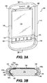
- Fig. 3A is a perspective top view of a handheld electronic device having an input portion in a first position, according to a first exemplary embodiment
- Fig. 3B is a partially schematic cross-sectional view taken along plane 3B-3B of Fig. 3A ;
- Fig. 3C is a perspective top view of a handheld electronic device having the input portion in a second position, according to the first exemplary embodiment
- Fig. 3D is a partially schematic cross-sectional view taken along plane 3D-3D of Fig. 3C ;
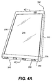
- Fig. 4A is a perspective top view of a handheld electronic device having the input portion in a first position, according to a second exemplary embodiment
- Fig. 4B is a perspective top view of a handheld electronic device having the input portion in a second position, according to the second exemplary embodiment
- Fig. 4C is a partially schematic cross-sectional view taken along plane 4C-4C of Fig. 4A ;
- Fig. 4D is a partially schematic cross-sectional view taken along plane 4D-4D of Fig. 4B ;
- Fig. 5A is a perspective top view of a handheld electronic device having the input portion in a first position, according to a third exemplary embodiment
- Fig. 5B is a perspective top view of a handheld electronic device having an input portion in a second position, according to the third exemplary embodiment.
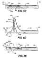
- Fig. 5C is a partially schematic cross-sectional view taken along plane 5C-5C of Fig. 5A ;
- Fig. 5D is a partially schematic cross-sectional view similar to that of Fig. 5A , showing the input portion intermediate to the first and second positions;
- Fig. 5E is a partially schematic cross-sectional view taken along plane 5E-5E of Fig. 5B .
- the disclosure generally relates to a handheld electronic device.
- handheld electronic devices include mobile wireless communication devices such as pagers, mobile phones, mobile smart-phones, wireless organizers, personal digital assistants, wireless-enabled notebook computers, and any other known communication device having a keypad.
- handheld electronic device 10 has a rigid form factor such as, for example, a bar or brick form factor. That is, handheld electronic device 10 has an exterior with a length dimension, a width dimension, and a height dimension that are fixed so that the exterior dimensions of handheld electronic device 10 are constant.
- handheld electronic device 10 includes a housing 11, and a flexible display 13 and an input portion 14 supported by housing 11.
- Flexible display 13 includes a flexible organic light-emitting diode (OLED) display, a flexible e-ink display, a flexible liquid crystal display (LCD), or another type of flexible display.
- Flexible display 13 has a length dimension that is parallel to a length dimension of housing 11. In some embodiments, flexible display may be a touch screen display.
- Input portion 14 is linked to flexible display 13. ln the illustrated embodiment depicted in Fig. 2 , a largest dimension of input portion 14 is parallel to a width dimension of housing 11. It should be understood, however, that in some embodiments, input portion 14 may be arranged such that a largest dimension of input portion 14 is parallel to a length dimension of housing 11. Input portion 14 has a user interface surface 15 which includes one or more input devices 16. Examples of such input devices 16 include, for example, a keyboard, keypad, touchpad, gamepad, or a track ball, or any other type of input device.
- input portion 14 is advantageously movable between a plurality of positions.
- input portion 14 can move between a first position illustrated in Fig. 1 and a second position illustrated in Fig. 2 .
- Input portion 14 and flexible display 13 are linked so that, when the input portion 14 is moved from the first position to the second position, flexible display 13 is rearranged and the viewable area of the flexible display 13 is reduced, and vice-versa.
- a substantial portion of interface surface 15 of input portion 14 is inaccessible to a user of handheld electronic device 10.
- a substantial portion of user interface surface 15 is parallel to a front face 12 of device 10.
- input devices 16 disposed on user interface surface 15 are operable by the user of the handheld electronic device 10.
- first viewing area 17 When input portion 14 is in the first position illustrated in Fig. 1 , a substantial portion of flexible display 13 is parallel to the front face 12 of device 10 to define a first viewing area 17. A length dimension of first viewing area 17 substantially corresponds to a length dimension of housing 11. When input portion 14 is in the second position illustrated in Fig. 2 , however, flexible display 13 is rearranged to define a second viewing area 18 that is smaller than the first viewing area 17.
- Handheld electronic device 100 includes a housing 110, an input portion 140, and a flexible display 130 associated with housing 110.
- Input portion 140 includes a user interface surface 150 having one or more input devices 160. While the user interface surface 150 of the depicted embodiment includes a keypad, it is contemplated that user interface surface 150 can include one or more other input devices 160 known to one of ordinary skill in the art.
- Flexible display 130 and input portion 140 are arranged with respect to housing 110 so as to permit translating movement of flexible display 130 and input portion 140 in a direction parallel to a length dimension of housing 110.
- An end 135 of flexible display 130 is linked to input portion 140. Accordingly, when input portion 140 is translated, e.g., by the user placing one or more fingers on input portion 140 and manually moving input portion 140 relative to housing 110 in a direction parallel to the length dimension of housing 110, input portion 140 and flexible display 130 translate together in the direction parallel to the length dimension of housing 110.
- Input portion 140 and flexible display 130 slide on tracks 195 formed in housing 110. It is contemplated, however, that input portion 140 and flexible display 130 may slide within a groove defined by housing 110 or may be guided in their movement relative to housing 110 by any other structural arrangement known to one of ordinary skill in the art.
- housing 110 includes a first recess 190a and a second recess 190b disposed in an interior of housing 110.
- First recess 190a and second recess 190b are configured to receive a portion of input portion 140 and a portion of flexible display 130, respectively.
- a substantial portion of flexible display 130 is parallel to a front face 120 of device 100 to define a first viewing area 170.
- a length dimension of first viewing area 170 substantially corresponds to the length dimension of housing 110.
- Figs. 3C and 3D depict input portion 140 in a second position, in which a substantial portion of user interface surface 150 of input portion 140 is parallel to front face 120 of device 100.
- flexible display 130 defines a second viewing area 180 that is less than the first viewing area 170.
- Handheld electronic device 100 includes a retainer arrangement configured to releasably retain input portion 140 in the first position ( Figs. 3A and 3B ) and in the second position ( Figs. 3C and 3D ), respectively.
- the retainer arrangement includes a first magnet 165b and a second magnet 165c that are configured to magnetically couple flexible display 130 and input portion 140, respectively, to a magnet 165a disposed in interior housing 115 when input portion 140 is in the first position ( Figs. 3A and 3B ) and in the second position ( Figs. 3C and 3D ).
- Magnets 165a, 165b, 165c releasably retain input portion 140 and flexible display 130 with respect to housing 110, when input portion 140 is in either the first position ( Figs. 3A and 3B ) or the second position ( Figs. 3C and 3D ).
- the tracks 195 in housing 110 that guide movement of input portion 140 and flexible display 130 with respect to housing 110 includes stops or limits 197 that prevent movement of input portion 140 beyond the first position ( Figs. 3A and 3B ) or the second position ( Fig. 3C and 3D ) after being moved from one position to another.
- input portion 140 When a user of the electronic handheld device 100 manually engages either input portion 140 or flexible display 130 and pushes it in a direction parallel to the length dimension of housing 110 with a sufficient force, input portion 140 is moved from the first position ( Figs. 3A and 3B ) or the second position ( Fig. 3C and 3D ) so that both input portion 140 and flexible display 130 slide relative to front face 120 of housing 110. In translating input portion 140 from the first position ( Figs. 3A and 3B ) to the second position ( Figs. 3C and 3D ), flexible display 130 is displaced into second recess 190b in housing 110.
- Figs. 3A-3D has an input portion 140 that is movable between a first position in which a substantial portion of input portion 140 is retracted within first recess 190a of housing 110 and a second position in which user interface surface 150 is substantially parallel to front face 120 of device 100
- input portion 140 may assume a plurality of positions therebetween.
- input portion 140 may assume a third position in which input portion 140 is partially retracted into first recess 190a in the interior of housing 110.
- flexible display 130 may be partially retracted within second recess 190b in the interior of housing 110 and define a third viewing area that is less than first viewing area 170 and greater than the second viewing area 180 (not shown).
- Handheld electronic device 200 includes a housing 210, and an input portion 240 and a flexible display 230 associated with housing 210.
- Input portion 240 is located at one end of housing 210 and includes a user interface surface 250 having one or more input devices 260.
- flexible display 230 may be a touch screen and the one or more input devices 260 may be navigations buttons.
- input portion 240 is mounted to rotate relative to housing 210 between a first position shown in Figs. 4A and 4C , and a second position shown in Figs. 4B and 4D .
- user interface surface 250 of input portion 240 is perpendicular to a front face 220 of device 200.
- user interface area 250 is parallel to front face 220 of device 200 and disposed on front face 220 of device 200.
- flexible display 230 When input portion 240 is in the first position, a substantial portion of flexible display 230 is parallel to front face 220 of device 200 to define a first viewing area 270. When input portion 240 is in the second position shown in Fig. 4B , flexible display 230 defines a second viewing area 280 that is smaller than the first viewing area 270.
- an end of flexible display 230 is linked to input portion 240.
- input portion 240 rotates from the first position illustrated in Figs. 4A and 4C to the second position illustrated in Figs. 4B and 4D , and a portion of flexible display 230 is displaced into a recess 290 in an interior 215 of housing 210. In this manner, flexible display 230 moves from the first arrangement illustrated in Fig. 4A to the second arrangement illustrated in Fig 4B .
- a suitable rotating arrangement allows input portion 240 to rotate, relative to housing 210, between the first position illustrated in Figs. 4A and 4C and the second position illustrated in Figs. 4B and 4D .
- the rotating arrangement includes a pin 225 projecting from opposite sides of input portion 240 and extending into similarly sized openings (not shown) in housing 210. Any suitable alternative arrangement may be used.
- Handheld electronic device 200 also includes a retainer arrangement configured to releasably retain input portion 240 in the first position (illustrated in Figs. 4A and 4C ) and in the second position (illustrated in Figs. 4B and 4D ), respectively.
- a retainer arrangement configured to releasably retain input portion 240 in the first position (illustrated in Figs. 4A and 4C ) and in the second position (illustrated in Figs. 4B and 4D ), respectively.
- the retainer arrangement includes a first magnet 265b and a second magnet 265c that are configured to magnetically couple input portion 240 to a magnet 265a disposed in interior 215 of housing 210 when input portion 240 is in the first position ( Figs. 4A and 4C ) and in the second position ( Figs.
- a stop or limit 297 is provided on input portion 240 to prevent rotation of input portion 240 beyond the second position after being moved from the first position to the second position.
- a similar stop or limit (not shown) is provided to prevent input portion 240 from rotating beyond the first position after being moved from the second position to the first position.
- Handheld electronic device 300 includes a housing 310, and an input portion 340 and a flexible display 330 associated with housing 310.
- Input portion 340 includes a user interface surface 350 having one or more input devices 360. It is contemplated that the one or more input devices 360 may include navigation keys and/or a keypad.
- input portion 340 is mounted to rotate relative to housing 310 between a first position shown in Figs. 5A and 5C , and a second position shown in Figs. 5B and 5E .
- user interface surface 350 of input portion 340 is disposed in a recess 390 facing an interior 315 of housing 310.
- user interface area 350 of input portion 340 is substantially parallel to front face 320 of device 300 and disposed on front face 320 of device 300.
- flexible display 330 When input portion 340 is in the first position, a substantial portion of flexible display 330 is parallel to front face 320 of device 300 to define a first viewing area 370. When input portion 340 is in the second position shown in Figs. 5B and 5E , flexible display 330 defines a second viewing area 380 that is smaller than the first viewing area 370.
- housing 310 includes a coupling movement mechanism 325 attached to input portion 340.
- Coupling movement mechanism 325 allows input portion 340 to pivot 180° relative to housing 310 between the first position illustrated in Figs. 5A and 5C and the second position illustrated in Figs. 5B and 5E .
- Many coupling movement mechanisms of handheld electronic devices are known to one of ordinary skill in the art and will not be described in detail herein. Any suitable mechanism may be used.
- coupling movement mechanism 325 may be a linkage mechanism including multiple gears (e.g., seven).
- Handheld electronic device 300 also includes a retainer arrangement configured to releasably retain input portion 340 in the first position ( Figs. 4A and 4C ) and in the second position ( Figs. 4B and 4D ).
- a retainer arrangement configured to releasably retain input portion 340 in the first position ( Figs. 4A and 4C ) and in the second position ( Figs. 4B and 4D ).
- input portion 340 includes one or more magnets 365b and 365c that are configured to magnetically couple input portion 340 to one or more magnets 365a disposed in recess 390 of housing 310 when input portion 340 is in the first position ( Figs. 5A and 5C ) and in the second position ( Figs. 5B and 5D ).
- coupling movement mechanism 325 includes a stop or limit 397 in the form of a releasable catch that movably extends into recess 390 and releasably engages input portion 340 thereby preventing movement of input portion 340 beyond the first position or the second position after being moved from one position to the other position.
- input portion 340 rotates from the first position illustrated in Figs. 5A and 5C to the second position illustrated in Figs. 5B and 5E , and a portion of flexible display 330 is displaced into the recess 390 in the interior 315 of housing 310. In this manner, flexible display 330 moves from the first arrangement illustrated in Figs. 5A and 5C to the second arrangement illustrated in Figs. 5B and 5E .
- the embodiments shown in the drawings allow users of the electronic handheld devices to select a desired flexible display area or a desired user interface surface without altering the overall dimensions of the handheld electronic device. In this manner, the handheld electronic devices are versatile while maintaining a small form factor.
Landscapes
- Engineering & Computer Science (AREA)
- Computer Hardware Design (AREA)
- Theoretical Computer Science (AREA)
- Signal Processing (AREA)
- Human Computer Interaction (AREA)
- Physics & Mathematics (AREA)
- General Engineering & Computer Science (AREA)
- General Physics & Mathematics (AREA)
- Telephone Set Structure (AREA)
Claims (12)
- Dispositif électronique tenu à la main, comprenant :un boîtier (11, 110, 210, 310) ayant une face avant ;un écran souple (13, 130, 230, 330) supporté sur la face avant du boîtier ;une section d'entrée (14, 140, 240, 340) fixée au boîtier, la section d'entrée étant mobile par rapport au boîtier entre une première position et une seconde position, la section d'entrée étant disposée sur la face avant du boîtier dans la seconde position,dans lequel la section d'entrée est liée à l'écran souple de façon que, lorsque la section d'entrée se déplace entre la première position et la seconde position, une partie de l'écran souple est réagencée par rapport à la face avant du boîtier,dans lequel la partie de l'écran souple est disposée dans un évidement à l'intérieur du boîtier lorsque la section d'entrée est dans la seconde position, etdans lequel l'écran souple possède une première zone (17, 170, 270, 370) de visualisation lorsque la section d'entrée est dans la première position et une seconde zone (18, 180, 280, 380) de visualisation lorsque la section d'entrée est dans la seconde position, la seconde zone de visualisation étant plus petite que la première zone de visualisation.
- Dispositif électronique tenu à la main selon la revendication 1, le dispositif étant configuré de façon que, lorsque la section d'entrée est dans la première position, une dimension en longueur de l'écran souple correspond pratiquement à une dimension en longueur du boîtier.
- Dispositif électronique tenu à la main selon la revendication 1, dans lequel la section d'entrée définit une surface (15, 150, 250, 350) d'interface d'utilisateur qui inclut un ou plusieurs dispositifs d'entrée (16, 160, 260, 360), et dans lequel la surface d'interface d'utilisateur n'est pas disposée sur la face avant du dispositif électronique tenu à la main lorsque la section d'entrée est dans la première position.
- Dispositif électronique tenu à la main selon la revendication 3, dans lequel une partie substantielle de la surface d'interface d'utilisateur est disposée sur la face avant lorsque la section d'entrée est dans la seconde position.
- Dispositif électronique tenu à la main selon la revendication 1, dans lequel les dimensions extérieures en longueur, en largeur et en hauteur du dispositif électronique tenu à la main sont les mêmes lorsque la section d'entrée est dans la première position et dans la seconde position.
- Dispositif électronique tenu à la main selon la revendication 1, dans lequel la section d'entrée et l'écran souple sont configurés pour se déplacer par rapport au boîtier pour donner un premier agencement de l'écran souple dans lequel une partie substantielle de l'écran souple est parallèle à la face avant du dispositif électronique tenu à la main, et un second agencement de l'écran souple dans lequel une partie de l'écran souple est disposée à l'intérieur de l'évidement.
- Dispositif électronique tenu à la main selon la revendication 6, dans lequel l'écran souple comporte la première zone de visualisation dans le premier agencement et la seconde zone de visualisation dans le second agencement.
- Dispositif électronique tenu à la main selon la revendication 7, dans lequel une dimension en longueur de la première zone de visualisation correspond substantiellement à une dimension en longueur du boîtier.
- Dispositif électronique tenu à la main selon la revendication 6, dans lequel la section d'entrée définit une surface (15, 150, 250, 350) d'interface d'utilisateur qui inclut un ou plusieurs dispositifs d'entrée (16, 160, 260, 360).
- Dispositif électronique tenu à la main selon la revendication 9, le dispositif étant configuré de façon que, lorsque l'écran souple est disposé à l'intérieur de l'évidement, une partie substantielle de la surface d'interface d'utilisateur de la section d'entrée est disposée sur la face avant du dispositif électronique tenu à la main.
- Dispositif électronique tenu à la main selon la revendication 6, dans lequel la section d'entrée est configurée pour se déplacer entre la première position et la seconde position pour opérer le mouvement de translation de l'écran entre le premier agencement et le second agencement.
- Dispositif électronique tenu à la main selon la revendication 8, dans lequel les dimensions extérieures en longueur, en largeur et en hauteur du dispositif électronique tenu à la main sont les mêmes lorsque l'écran souple est dans le premier agencement et dans le second agencement.
Priority Applications (2)
| Application Number | Priority Date | Filing Date | Title |
|---|---|---|---|
| EP11176714.1A EP2555080B1 (fr) | 2011-08-05 | 2011-08-05 | Dispositif électronique portable doté d'un affichage souple |
| CA2782393A CA2782393C (fr) | 2011-08-05 | 2012-06-29 | Appareil electronique portatif muni d'un affichage flexible |
Applications Claiming Priority (1)
| Application Number | Priority Date | Filing Date | Title |
|---|---|---|---|
| EP11176714.1A EP2555080B1 (fr) | 2011-08-05 | 2011-08-05 | Dispositif électronique portable doté d'un affichage souple |
Publications (2)
| Publication Number | Publication Date |
|---|---|
| EP2555080A1 EP2555080A1 (fr) | 2013-02-06 |
| EP2555080B1 true EP2555080B1 (fr) | 2013-07-17 |
Family
ID=44582342
Family Applications (1)
| Application Number | Title | Priority Date | Filing Date |
|---|---|---|---|
| EP11176714.1A Active EP2555080B1 (fr) | 2011-08-05 | 2011-08-05 | Dispositif électronique portable doté d'un affichage souple |
Country Status (2)
| Country | Link |
|---|---|
| EP (1) | EP2555080B1 (fr) |
| CA (1) | CA2782393C (fr) |
Family Cites Families (5)
| Publication number | Priority date | Publication date | Assignee | Title |
|---|---|---|---|---|
| US20030104850A1 (en) * | 2001-12-04 | 2003-06-05 | Cheng-Shing Lai | PDA with a protective cover for its display panel |
| US20050132292A1 (en) * | 2003-12-11 | 2005-06-16 | Chen-Ming Nien | Electronic device |
| ATE395779T1 (de) * | 2005-04-11 | 2008-05-15 | Sony Ericsson Mobile Comm Ab | Verschiebbare tastatur für ein elektronisches gerät |
| CN1893288A (zh) * | 2005-07-05 | 2007-01-10 | 摩托罗拉公司 | 用于电子设备的可移动用户界面 |
| KR101427264B1 (ko) * | 2007-12-17 | 2014-08-06 | 엘지전자 주식회사 | 휴대 단말기 |
-
2011
- 2011-08-05 EP EP11176714.1A patent/EP2555080B1/fr active Active
-
2012
- 2012-06-29 CA CA2782393A patent/CA2782393C/fr active Active
Also Published As
| Publication number | Publication date |
|---|---|
| EP2555080A1 (fr) | 2013-02-06 |
| CA2782393A1 (fr) | 2013-02-05 |
| CA2782393C (fr) | 2017-01-03 |
Similar Documents
| Publication | Publication Date | Title |
|---|---|---|
| US8811032B2 (en) | Handheld electronic device having a flexible display | |
| US11567540B2 (en) | Foldable device | |
| EP2595029A1 (fr) | Dispositif électronique portable doté d'un affichage souple | |
| US20130120912A1 (en) | Handheld electronic device having a flexible display | |
| EP3661177B1 (fr) | Dispositif électronique portable | |
| US8539705B2 (en) | Crossfold electronic device | |
| US7099708B2 (en) | Foldable/Slidable Function Keyboard for an Electronic Device | |
| US8230992B2 (en) | Tablet computer case for multiple viewing orientations | |
| US8412280B2 (en) | Electronic apparatus | |
| CN103123519B (zh) | 便携式计算机 | |
| US9134758B2 (en) | Connecting mechanism and electronic device using the same | |
| US8111506B2 (en) | Electronic device | |
| CN104850177B (zh) | 具有收纳功能的电子装置 | |
| TWI333407B (en) | Portable electronic device having auxiliary input unit | |
| US20100016043A1 (en) | Slide Mechanism and Electronic Apparatus | |
| EP2273770A1 (fr) | Dispositif électronique et mécanisme coulissant semi-automatique correspondant | |
| US8174501B2 (en) | Computer having interlocking L-shape components | |
| US8085532B2 (en) | Electronic device | |
| EP2555080B1 (fr) | Dispositif électronique portable doté d'un affichage souple | |
| US9261907B2 (en) | Electronic device | |
| US8662769B2 (en) | Keyboard with rotatable portion | |
| CN100520677C (zh) | 可携式电子装置 | |
| JP5448171B2 (ja) | キー入力装置および電子機器 | |
| US9285838B2 (en) | Electronic device | |
| US20130293474A1 (en) | Handheld electronic device having a slidable keyboard |
Legal Events
| Date | Code | Title | Description |
|---|---|---|---|
| PUAI | Public reference made under article 153(3) epc to a published international application that has entered the european phase |
Free format text: ORIGINAL CODE: 0009012 |
|
| 17P | Request for examination filed |
Effective date: 20110805 |
|
| AK | Designated contracting states |
Kind code of ref document: A1 Designated state(s): AL AT BE BG CH CY CZ DE DK EE ES FI FR GB GR HR HU IE IS IT LI LT LU LV MC MK MT NL NO PL PT RO RS SE SI SK SM TR |
|
| AX | Request for extension of the european patent |
Extension state: BA ME |
|
| GRAP | Despatch of communication of intention to grant a patent |
Free format text: ORIGINAL CODE: EPIDOSNIGR1 |
|
| GRAS | Grant fee paid |
Free format text: ORIGINAL CODE: EPIDOSNIGR3 |
|
| GRAA | (expected) grant |
Free format text: ORIGINAL CODE: 0009210 |
|
| AK | Designated contracting states |
Kind code of ref document: B1 Designated state(s): AL AT BE BG CH CY CZ DE DK EE ES FI FR GB GR HR HU IE IS IT LI LT LU LV MC MK MT NL NO PL PT RO RS SE SI SK SM TR |
|
| REG | Reference to a national code |
Ref country code: GB Ref legal event code: FG4D |
|
| REG | Reference to a national code |
Ref country code: CH Ref legal event code: EP |
|
| REG | Reference to a national code |
Ref country code: IE Ref legal event code: FG4D |
|
| REG | Reference to a national code |
Ref country code: AT Ref legal event code: REF Ref document number: 622588 Country of ref document: AT Kind code of ref document: T Effective date: 20130815 Ref country code: CH Ref legal event code: PFA Owner name: BLACKBERRY LIMITED, CA Free format text: FORMER OWNER: RESEARCH IN MOTION LIMITED, CA |
|
| RAP2 | Party data changed (patent owner data changed or rights of a patent transferred) |
Owner name: BLACKBERRY LIMITED |
|
| REG | Reference to a national code |
Ref country code: DE Ref legal event code: R096 Ref document number: 602011002377 Country of ref document: DE Effective date: 20130912 |
|
| REG | Reference to a national code |
Ref country code: NL Ref legal event code: TD Effective date: 20131022 |
|
| REG | Reference to a national code |
Ref country code: CH Ref legal event code: PCOW Free format text: NEW ADDRESS: 2200 UNIVERSITY AVENUE EAST, WATERLOO, ON N2K 0A7 (CA) |
|
| REG | Reference to a national code |
Ref country code: NL Ref legal event code: T3 |
|
| RAP2 | Party data changed (patent owner data changed or rights of a patent transferred) |
Owner name: BLACKBERRY LIMITED |
|
| REG | Reference to a national code |
Ref country code: AT Ref legal event code: MK05 Ref document number: 622588 Country of ref document: AT Kind code of ref document: T Effective date: 20130717 |
|
| REG | Reference to a national code |
Ref country code: LT Ref legal event code: MG4D |
|
| PG25 | Lapsed in a contracting state [announced via postgrant information from national office to epo] |
Ref country code: PT Free format text: LAPSE BECAUSE OF FAILURE TO SUBMIT A TRANSLATION OF THE DESCRIPTION OR TO PAY THE FEE WITHIN THE PRESCRIBED TIME-LIMIT Effective date: 20131118 Ref country code: AT Free format text: LAPSE BECAUSE OF FAILURE TO SUBMIT A TRANSLATION OF THE DESCRIPTION OR TO PAY THE FEE WITHIN THE PRESCRIBED TIME-LIMIT Effective date: 20130717 Ref country code: NO Free format text: LAPSE BECAUSE OF FAILURE TO SUBMIT A TRANSLATION OF THE DESCRIPTION OR TO PAY THE FEE WITHIN THE PRESCRIBED TIME-LIMIT Effective date: 20131017 Ref country code: LT Free format text: LAPSE BECAUSE OF FAILURE TO SUBMIT A TRANSLATION OF THE DESCRIPTION OR TO PAY THE FEE WITHIN THE PRESCRIBED TIME-LIMIT Effective date: 20130717 Ref country code: IS Free format text: LAPSE BECAUSE OF FAILURE TO SUBMIT A TRANSLATION OF THE DESCRIPTION OR TO PAY THE FEE WITHIN THE PRESCRIBED TIME-LIMIT Effective date: 20131117 Ref country code: CY Free format text: LAPSE BECAUSE OF FAILURE TO SUBMIT A TRANSLATION OF THE DESCRIPTION OR TO PAY THE FEE WITHIN THE PRESCRIBED TIME-LIMIT Effective date: 20130918 Ref country code: BE Free format text: LAPSE BECAUSE OF FAILURE TO SUBMIT A TRANSLATION OF THE DESCRIPTION OR TO PAY THE FEE WITHIN THE PRESCRIBED TIME-LIMIT Effective date: 20130717 Ref country code: SE Free format text: LAPSE BECAUSE OF FAILURE TO SUBMIT A TRANSLATION OF THE DESCRIPTION OR TO PAY THE FEE WITHIN THE PRESCRIBED TIME-LIMIT Effective date: 20130717 Ref country code: HR Free format text: LAPSE BECAUSE OF FAILURE TO SUBMIT A TRANSLATION OF THE DESCRIPTION OR TO PAY THE FEE WITHIN THE PRESCRIBED TIME-LIMIT Effective date: 20130717 |
|
| PG25 | Lapsed in a contracting state [announced via postgrant information from national office to epo] |
Ref country code: GR Free format text: LAPSE BECAUSE OF FAILURE TO SUBMIT A TRANSLATION OF THE DESCRIPTION OR TO PAY THE FEE WITHIN THE PRESCRIBED TIME-LIMIT Effective date: 20131018 Ref country code: PL Free format text: LAPSE BECAUSE OF FAILURE TO SUBMIT A TRANSLATION OF THE DESCRIPTION OR TO PAY THE FEE WITHIN THE PRESCRIBED TIME-LIMIT Effective date: 20130717 Ref country code: FI Free format text: LAPSE BECAUSE OF FAILURE TO SUBMIT A TRANSLATION OF THE DESCRIPTION OR TO PAY THE FEE WITHIN THE PRESCRIBED TIME-LIMIT Effective date: 20130717 Ref country code: LV Free format text: LAPSE BECAUSE OF FAILURE TO SUBMIT A TRANSLATION OF THE DESCRIPTION OR TO PAY THE FEE WITHIN THE PRESCRIBED TIME-LIMIT Effective date: 20130717 Ref country code: ES Free format text: LAPSE BECAUSE OF FAILURE TO SUBMIT A TRANSLATION OF THE DESCRIPTION OR TO PAY THE FEE WITHIN THE PRESCRIBED TIME-LIMIT Effective date: 20131028 |
|
| PG25 | Lapsed in a contracting state [announced via postgrant information from national office to epo] |
Ref country code: CY Free format text: LAPSE BECAUSE OF FAILURE TO SUBMIT A TRANSLATION OF THE DESCRIPTION OR TO PAY THE FEE WITHIN THE PRESCRIBED TIME-LIMIT Effective date: 20130717 |
|
| PG25 | Lapsed in a contracting state [announced via postgrant information from national office to epo] |
Ref country code: EE Free format text: LAPSE BECAUSE OF FAILURE TO SUBMIT A TRANSLATION OF THE DESCRIPTION OR TO PAY THE FEE WITHIN THE PRESCRIBED TIME-LIMIT Effective date: 20130717 Ref country code: CZ Free format text: LAPSE BECAUSE OF FAILURE TO SUBMIT A TRANSLATION OF THE DESCRIPTION OR TO PAY THE FEE WITHIN THE PRESCRIBED TIME-LIMIT Effective date: 20130717 Ref country code: DK Free format text: LAPSE BECAUSE OF FAILURE TO SUBMIT A TRANSLATION OF THE DESCRIPTION OR TO PAY THE FEE WITHIN THE PRESCRIBED TIME-LIMIT Effective date: 20130717 Ref country code: RO Free format text: LAPSE BECAUSE OF FAILURE TO SUBMIT A TRANSLATION OF THE DESCRIPTION OR TO PAY THE FEE WITHIN THE PRESCRIBED TIME-LIMIT Effective date: 20130717 Ref country code: SK Free format text: LAPSE BECAUSE OF FAILURE TO SUBMIT A TRANSLATION OF THE DESCRIPTION OR TO PAY THE FEE WITHIN THE PRESCRIBED TIME-LIMIT Effective date: 20130717 Ref country code: MC Free format text: LAPSE BECAUSE OF FAILURE TO SUBMIT A TRANSLATION OF THE DESCRIPTION OR TO PAY THE FEE WITHIN THE PRESCRIBED TIME-LIMIT Effective date: 20130717 |
|
| REG | Reference to a national code |
Ref country code: IE Ref legal event code: MM4A |
|
| PLBE | No opposition filed within time limit |
Free format text: ORIGINAL CODE: 0009261 |
|
| STAA | Information on the status of an ep patent application or granted ep patent |
Free format text: STATUS: NO OPPOSITION FILED WITHIN TIME LIMIT |
|
| PG25 | Lapsed in a contracting state [announced via postgrant information from national office to epo] |
Ref country code: IT Free format text: LAPSE BECAUSE OF FAILURE TO SUBMIT A TRANSLATION OF THE DESCRIPTION OR TO PAY THE FEE WITHIN THE PRESCRIBED TIME-LIMIT Effective date: 20130717 |
|
| 26N | No opposition filed |
Effective date: 20140422 |
|
| PG25 | Lapsed in a contracting state [announced via postgrant information from national office to epo] |
Ref country code: IE Free format text: LAPSE BECAUSE OF NON-PAYMENT OF DUE FEES Effective date: 20130805 |
|
| REG | Reference to a national code |
Ref country code: DE Ref legal event code: R097 Ref document number: 602011002377 Country of ref document: DE Effective date: 20140422 |
|
| REG | Reference to a national code |
Ref country code: DE Ref legal event code: R082 Ref document number: 602011002377 Country of ref document: DE Representative=s name: MERH-IP MATIAS ERNY REICHL HOFFMANN, DE |
|
| REG | Reference to a national code |
Ref country code: DE Ref legal event code: R082 Ref document number: 602011002377 Country of ref document: DE Representative=s name: MERH-IP MATIAS ERNY REICHL HOFFMANN PATENTANWA, DE Effective date: 20140926 Ref country code: DE Ref legal event code: R082 Ref document number: 602011002377 Country of ref document: DE Representative=s name: MERH-IP MATIAS ERNY REICHL HOFFMANN, DE Effective date: 20140926 Ref country code: DE Ref legal event code: R081 Ref document number: 602011002377 Country of ref document: DE Owner name: BLACKBERRY LIMITED, WATERLOO, CA Free format text: FORMER OWNER: RESEARCH IN MOTION LIMITED, WATERLOO, ONTARIO, CA Effective date: 20140926 |
|
| REG | Reference to a national code |
Ref country code: CH Ref legal event code: PL |
|
| PG25 | Lapsed in a contracting state [announced via postgrant information from national office to epo] |
Ref country code: LI Free format text: LAPSE BECAUSE OF NON-PAYMENT OF DUE FEES Effective date: 20140831 Ref country code: CH Free format text: LAPSE BECAUSE OF NON-PAYMENT OF DUE FEES Effective date: 20140831 |
|
| PG25 | Lapsed in a contracting state [announced via postgrant information from national office to epo] |
Ref country code: SM Free format text: LAPSE BECAUSE OF FAILURE TO SUBMIT A TRANSLATION OF THE DESCRIPTION OR TO PAY THE FEE WITHIN THE PRESCRIBED TIME-LIMIT Effective date: 20130717 |
|
| PG25 | Lapsed in a contracting state [announced via postgrant information from national office to epo] |
Ref country code: MT Free format text: LAPSE BECAUSE OF FAILURE TO SUBMIT A TRANSLATION OF THE DESCRIPTION OR TO PAY THE FEE WITHIN THE PRESCRIBED TIME-LIMIT Effective date: 20130717 Ref country code: TR Free format text: LAPSE BECAUSE OF FAILURE TO SUBMIT A TRANSLATION OF THE DESCRIPTION OR TO PAY THE FEE WITHIN THE PRESCRIBED TIME-LIMIT Effective date: 20130717 |
|
| PG25 | Lapsed in a contracting state [announced via postgrant information from national office to epo] |
Ref country code: HU Free format text: LAPSE BECAUSE OF FAILURE TO SUBMIT A TRANSLATION OF THE DESCRIPTION OR TO PAY THE FEE WITHIN THE PRESCRIBED TIME-LIMIT; INVALID AB INITIO Effective date: 20110805 Ref country code: SI Free format text: LAPSE BECAUSE OF NON-PAYMENT OF DUE FEES Effective date: 20140110 Ref country code: MK Free format text: LAPSE BECAUSE OF FAILURE TO SUBMIT A TRANSLATION OF THE DESCRIPTION OR TO PAY THE FEE WITHIN THE PRESCRIBED TIME-LIMIT Effective date: 20130717 Ref country code: BG Free format text: LAPSE BECAUSE OF FAILURE TO SUBMIT A TRANSLATION OF THE DESCRIPTION OR TO PAY THE FEE WITHIN THE PRESCRIBED TIME-LIMIT Effective date: 20130717 Ref country code: LU Free format text: LAPSE BECAUSE OF NON-PAYMENT OF DUE FEES Effective date: 20130805 Ref country code: RS Free format text: LAPSE BECAUSE OF FAILURE TO SUBMIT A TRANSLATION OF THE DESCRIPTION OR TO PAY THE FEE WITHIN THE PRESCRIBED TIME-LIMIT Effective date: 20131017 |
|
| REG | Reference to a national code |
Ref country code: FR Ref legal event code: PLFP Year of fee payment: 6 |
|
| REG | Reference to a national code |
Ref country code: FR Ref legal event code: PLFP Year of fee payment: 7 |
|
| REG | Reference to a national code |
Ref country code: FR Ref legal event code: PLFP Year of fee payment: 8 |
|
| PG25 | Lapsed in a contracting state [announced via postgrant information from national office to epo] |
Ref country code: AL Free format text: LAPSE BECAUSE OF FAILURE TO SUBMIT A TRANSLATION OF THE DESCRIPTION OR TO PAY THE FEE WITHIN THE PRESCRIBED TIME-LIMIT Effective date: 20130717 |
|
| REG | Reference to a national code |
Ref country code: DE Ref legal event code: R082 Ref document number: 602011002377 Country of ref document: DE Ref country code: DE Ref legal event code: R081 Ref document number: 602011002377 Country of ref document: DE Owner name: MALIKIE INNOVATIONS LTD., IE Free format text: FORMER OWNER: BLACKBERRY LIMITED, WATERLOO, ONTARIO, CA |
|
| PGFP | Annual fee paid to national office [announced via postgrant information from national office to epo] |
Ref country code: NL Payment date: 20250825 Year of fee payment: 15 |
|
| PGFP | Annual fee paid to national office [announced via postgrant information from national office to epo] |
Ref country code: DE Payment date: 20250827 Year of fee payment: 15 |
|
| PGFP | Annual fee paid to national office [announced via postgrant information from national office to epo] |
Ref country code: GB Payment date: 20250826 Year of fee payment: 15 |
|
| PGFP | Annual fee paid to national office [announced via postgrant information from national office to epo] |
Ref country code: FR Payment date: 20250825 Year of fee payment: 15 |