EP2555313A2 - Dispositif de batterie de stockage - Google Patents
Dispositif de batterie de stockage Download PDFInfo
- Publication number
- EP2555313A2 EP2555313A2 EP20120164156 EP12164156A EP2555313A2 EP 2555313 A2 EP2555313 A2 EP 2555313A2 EP 20120164156 EP20120164156 EP 20120164156 EP 12164156 A EP12164156 A EP 12164156A EP 2555313 A2 EP2555313 A2 EP 2555313A2
- Authority
- EP
- European Patent Office
- Prior art keywords
- storage battery
- alternating current
- output
- battery
- inverter
- Prior art date
- Legal status (The legal status is an assumption and is not a legal conclusion. Google has not performed a legal analysis and makes no representation as to the accuracy of the status listed.)
- Withdrawn
Links
Images


Classifications
-
- H—ELECTRICITY
- H01—ELECTRIC ELEMENTS
- H01M—PROCESSES OR MEANS, e.g. BATTERIES, FOR THE DIRECT CONVERSION OF CHEMICAL ENERGY INTO ELECTRICAL ENERGY
- H01M10/00—Secondary cells; Manufacture thereof
- H01M10/60—Heating or cooling; Temperature control
- H01M10/63—Control systems
- H01M10/637—Control systems characterised by the use of reversible temperature-sensitive devices, e.g. NTC, PTC or bimetal devices; characterised by control of the internal current flowing through the cells, e.g. by switching
-
- H—ELECTRICITY
- H01—ELECTRIC ELEMENTS
- H01M—PROCESSES OR MEANS, e.g. BATTERIES, FOR THE DIRECT CONVERSION OF CHEMICAL ENERGY INTO ELECTRICAL ENERGY
- H01M10/00—Secondary cells; Manufacture thereof
- H01M10/60—Heating or cooling; Temperature control
- H01M10/62—Heating or cooling; Temperature control specially adapted for specific applications
- H01M10/625—Vehicles
-
- H—ELECTRICITY
- H01—ELECTRIC ELEMENTS
- H01M—PROCESSES OR MEANS, e.g. BATTERIES, FOR THE DIRECT CONVERSION OF CHEMICAL ENERGY INTO ELECTRICAL ENERGY
- H01M2220/00—Batteries for particular applications
- H01M2220/20—Batteries in motive systems, e.g. vehicle, ship, plane
-
- Y—GENERAL TAGGING OF NEW TECHNOLOGICAL DEVELOPMENTS; GENERAL TAGGING OF CROSS-SECTIONAL TECHNOLOGIES SPANNING OVER SEVERAL SECTIONS OF THE IPC; TECHNICAL SUBJECTS COVERED BY FORMER USPC CROSS-REFERENCE ART COLLECTIONS [XRACs] AND DIGESTS
- Y02—TECHNOLOGIES OR APPLICATIONS FOR MITIGATION OR ADAPTATION AGAINST CLIMATE CHANGE
- Y02E—REDUCTION OF GREENHOUSE GAS [GHG] EMISSIONS, RELATED TO ENERGY GENERATION, TRANSMISSION OR DISTRIBUTION
- Y02E60/00—Enabling technologies; Technologies with a potential or indirect contribution to GHG emissions mitigation
- Y02E60/10—Energy storage using batteries
Definitions
- Embodiments described herein relate generally to a storage battery device having a warm-up function.
- the car is required to start easily even in a low-temperature atmosphere in which the ambient temperature is approximately -30°C. Therefore, it is required to take some remedies for storage batteries having characteristics in which the output power is reduced in the low-temperature atmosphere.
- a method for warming the storage battery is proposed as a method for compensating for a reduction in the output power of the storage battery in the low-temperature atmosphere.
- the following methods are proposed as the method for warming the storage battery.
- a storage battery device which passes a current without causing charging/discharging on average through a battery by supplying an alternating current to the battery at the low-temperature time, heats the battery from inside to warm the battery and stabilizes the output characteristic of the battery.
- the storage battery device includes a storage battery, an alternating current generation device, and a DC blocking filter.
- the storage battery includes an internal resistor that converts power energy passed therethrough to thermal energy.
- the alternating current generation device includes an alternating current generation device that supplies an alternating current to the storage battery and the DC blocking filter blocks a direct current output to the alternating current generation device from the storage battery.
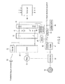
- FIG. 1 is a block diagram showing the simplified configuration of a hybrid car using two driving sources of a motor and engine. An example in which this embodiment is applied to the hybrid car is explained, but this application example does not limit the scope of this invention.
- FIG. 1 a plurality of cells are connected in series as a storage battery 11.
- the storage battery is represented as one battery having the cells provided therein.
- the storage battery 11 is connected to the positive and negative terminals of an inverter 20 via coils L1, L2 that block an alternating current (and/or an AC voltage).
- An AC blocking filter 12 includes coils L1, L2.
- a circuit between the positive and negative terminals of the storage battery 11 and the positive and negative terminals of the inverter 20 may be referred to as a main wiring circuit in some cases.
- the blocking effect of the AC blocking filter 12 becomes more significant as the frequency of an alternating current supplied from an alternating current generation device 10 becomes higher. Therefore, if a low frequency is used, the AC blocking filter 12 may sometimes not be used.
- the positive and negative output terminals of a charger 22 may be connected to the positive and negative terminals of the storage battery 11 via coils L1, L2.
- a plug 23 used for drawing power from the exterior at the time of charging to the storage battery 11 is provided in the charger 22.
- a car having the above function is called a plug-in hybrid car and is a vehicle having a mechanism capable of charging the storage battery 11 from the exterior of the car.
- the AC output terminals of the alternating current generation device 10 are connected to the positive and negative terminals of the storage battery 11 via capacitors C1, C2.
- a DC blocking filter 13 includes capacitors C1, C2.
- a control unit 50 is a control device that controls an inverter, storage battery, engine and the like. It acquires temperature information of a battery from a battery-monitoring unit of the storage battery 11. When the temperature of the storage battery 11 becomes lower than a preset temperature previously set, the control unit 50 turns on the alternating current generation device 10. Then, the alternating current generation device 10 supplies an alternating current to the storage battery 11. Since a DC output of the storage battery 11 is blocked by means of the DC blocking filter 13, a reverse current to the alternating current generation device 10 is prevented. Further, since an alternating current from the alternating current generation device 10 is blocked by means of the AC blocking filter 12, input to the inverter 20 is prevented.
- the battery is heated by an alternating current flowing through the internal resistor of the battery and the temperature of the storage battery 11 rises.
- the AC blocking filter 12 is provided on the inverter 20 side, an alternating current supplied from the alternating current generation device 10 is suppressed from flowing into the input capacitor of the inverter 20 and the storage battery 11 can be efficiently warmed.
- the state of charge (SOC) of the battery is kept unchanged. Further, if the frequency range used is adequately selected, a large alternating current can be supplied while suppressing deterioration of the storage battery 11 and the storage battery 11 can rapidly and efficiently be warmed. As the frequency range, a frequency near the resonance frequency of the storage battery 11 may be selected, for example.
- control unit 50 interrupts output of the alternating current generation device 10 and interrupts supply of an alternating current to the storage battery 11.
- the inverter 20 converts a DC voltage from the storage battery 11 to a three-phase alternating current and supplies the same to a motor 31.
- the rotation power of the motor 31 is transmitted to a wheel 33 via a decelerator 32. At this time, that is, when the decelerated rotation power of the motor 31 is transmitted to the wheel 33, the rotation power is added to the rotation power of an engine 41 using oil or natural gas as an energy source and then transmitted to the wheel 33.
- the rotation of a shaft of the engine 41 is transmitted to a generator (that may be called an alternator) 42.
- a three-phase alternating current generated from the generator 42 is rectified by means of a rectifier 43 and then charged to an auxiliary battery 44 (for example, 12 V).
- the auxiliary battery 44 is used as a power source of onboard electrical equipment such as operating power sources for onboard lights, car navigator, ignition of an engine, cooling device and the like, a power source of the control unit 50 and the like.
- motion energy of the car obtained from the wheel 33 can be regenerated to the storage battery 11 by using the motor 31 as a generator based on the control of the control unit 50. Further, the storage battery 11 may be charged by means of the engine 41 by driving the motor 31 as a generator.
- the motor 31 is used not only as the electric motor but also as the generator, but the electric motor and generator can be separately mounted.
- the alternating current generation device 10 can variously be formed in embodiments and is explained below.
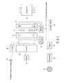
- FIG. 2 shows another embodiment.
- the same portions as those of FIG. 1 are denoted by the same symbols as those of FIG. 1 and the repetitive explanation is omitted.
- the AC output terminals of a multiphase/two-phase converter 46 (for example, a Scott transformer) are connected to the positive and negative terminals of a storage battery 11 via capacitors C1, C2.
- Capacitors C1, C2 configure a DC blocking filter 13.
- a three-phase alternating current generated form a generator 42 is further coupled to the multiphase/two-phase converter 46 via a switch 45.
- the switch 45 is on/off-controlled by means of a control unit 50.
- the control unit 50 receives temperature information of a battery from a battery-monitoring unit of the storage battery 11. When the temperature of the storage battery 11 becomes lower than a preset temperature, the control unit 50 turns on the switch 45. Then, the multiphase/two-phase converter 46 converts a three-phase output of the generator 42 to a two-phase alternating current and supplies the same to the storage battery 11. Since the DC output of the storage battery 11 is blocked by means of the DC blocking filter 13, a reverse current will not be supplied to the multiphase/two-phase converter 46. Further, since the alternating current from the multiphase/two-phase converter 46 is blocked by means of an AC blocking filter 12, the current will not be input to the inverter 20.
- the battery is heated by an alternating current flowing through the internal resistor of the battery and the storage battery 11 is warmed.
- the control unit 50 opens the switch 45 to interrupt supply of the alternating current to the storage battery 11.
- the rotation speed of the engine 41 can be controlled to be set in a target frequency range based on the control unit 50 while the alternating current is being supplied to the storage battery 11. Further, a fuel supply amount to the engine 41 can be adjusted based on the control of the control unit 50 to compensate for a load variation of the engine 41 caused by a load variation of the generator 42 that varies according to the on/off state of the switch 45.
- the generator 42 is directly coupled with the output shaft of the engine 41, but may be connected thereto via a decelerator or another power transmission means.
- the generators supply the same power, the loss of one of the generators tends to become smaller as an output voltage thereof becomes higher. Therefore, it is preferable to adjust the turn ratio of the transformer and set a high-voltage small current on the primary side (generator 42 side) and a low-voltage large current on the secondary side (storage battery side) at the multiphase/two-phase conversion time instead of acquiring a low-voltage large current required for warming the storage battery 11 directly from the generator 42. If the generator 42 is of a two-phase output type, the multiphase/two-phase conversion becomes unnecessary.
- the storage battery 11 includes 100 cells, for example, and the output voltage thereof is selected in a range of 200 to 400 V, for example.
- the present system may be designed to make it possible to select the power (current and voltage) of a high-frequency alternating current used for warming the battery based on the scale of the storage battery 11 and various conditions.
- the difference (A2-A1) between present temperature A1 of the battery and target high temperature A2 and time T required for reaching temperature A2 may be previously actually measured and measurement data may be stored in a memory as a table. Then, the present system may be designed to make it possible to freely select a combination of a current of 1, 5 and 10 A and a voltage of 1, 10 and 20 V, for example, as an alternating current as required time T becomes shorter. Since the temperature-rise characteristics at the warming time are different according to the protection cover and arrangement state of the storage battery 11 and the output standard of the storage battery 11, a plurality of tables of the measurement data may be formed for the respective storage batteries.
- Adjustment means capable of adjusting the period and time in which the warming operation for the storage battery 11 is performed according to the use environment of a car (for example, a case wherein an emergency start is required as in an ambulance or a case of parking for a long time) may be provided between the control unit and operating unit.
- FIG. 3 shows still another embodiment.
- the above embodiment shows a case wherein the generator 42 is provided on the engine 41 and an AC output of the generator 42 is converted to a high-frequency alternating current to be supplied to the storage battery 11.
- FIG. 3 shows one example of a storage battery device that can be applied to a car of this type.
- the same portions as those of FIG. 2 are denoted by the same symbols as those of FIG. 2 and the repetitive explanation thereof is omitted.
- the positive and negative input terminals of a DC-DC converter 47 are connected to the positive and negative terminals of a storage battery 11 via an AC blocking filter 12.
- An output voltage of 12 V, for example, converted by the DC-DC converter 47 is supplied to an auxiliary battery 44.
- the output terminal of the auxiliary battery 44 is connected to the input terminal of a warming inverter 48.
- the output terminal of the warming inverter 48 is connected to the storage battery 11 via a DC blocking filter 13.
- the warming inverter 48 is an inverter controlled by a control unit 50. When determining that the storage battery 11 is to be warmed, the control unit 50 drives the warming inverter 48. The warming inverter 48 performs DC-AC conversion to output an alternating current and supplies the alternating current to the storage battery 11. As a result, the storage battery 11 is heated and warmed.
- the warming inverter 48 includes a semiconductor switch element (field-effect transistor [FET], insulated-gate bipolar transistor [TGBT] or the like) for a switching operation.
- FET field-effect transistor
- TGBT insulated-gate bipolar transistor
- power of the auxiliary battery 44 is converted to an alternating current by means of the warming inverter 48.
- this embodiment is not limited to this case and power can be directly obtained from the storage battery 11.
- the storage battery 11 can be warmed while suppressing the power consumption of the auxiliary battery 44.
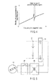
- the storage battery uses metal such as aluminum for the electrodes and the AC impedance between the positive and negative electrodes exhibits an inductive impedance characteristic in a relatively high frequency (approximately 100 kHz or more). For this reason, a resonance point as shown in FIG. 4 exists in the AC impedance between the positive and negative electrodes of the storage battery.
- the abscissa represents a frequency and the ordinate represents the absolute value of AC impedance.
- a current that does not cause charging/discharging is passed through the battery to heat the battery from the internal portion and warm the battery and the output characteristic at the low-temperature time can be improved by supplying an alternating current to the battery at the low-temperature time.
- FIG. 5 shows the principle of the internal configuration of the generator 42, switch 45 and multiphase/two-phase converter 46 shown in FIG. 2 .
- a rotor of the generator 42 having a permanent magnet When a rotor of the generator 42 having a permanent magnet is rotated and driven by the engine 41, an induction current flows through a stator having a coil and is output as an alternating current (in this example, a two-phase alternating current).
- the alternating current is supplied to a multiphase/two-phase converter 46 (in this example, two-phase/two-phase converter) via the switch 45.
- the turn ratio of the converter 46 is adequately adjusted to set a high-voltage small current on the primary side (generator 42 side) and a low-voltage large current on the secondary side (storage battery side).
- the switch 45 is turned on and an output current of the converter 46 is supplied to the storage battery 11 via the DC blocking filter 13.
- FIG. 6 shows the principle of the internal configuration of the warming inverter 48 shown in FIG. 3 .
- the input electrode of a switching transistor 48a is connected to the positive electrode of the auxiliary battery 44 and the output electrode of the switching transistor 48a is connected to an earth line via the primary winding of a transformer 48b.
- the secondary winding of the transformer 48b is connected to the storage battery 11 via the DC blocking filter 13.
- An on/off control signal of the switching transistor 48a is obtained from the control unit 50.
- FIG. 7 shows an example in which current amount adjusters 61a, 61b are provided in a passage through which an alternating current for warming is supplied to the storage battery 11.
- the current amount adjusters 61a, 61b are controlled by the control unit 50.
- the current amount may be varied according to a variation in the battery temperature. That is, when supply of an alternating current is started, the battery temperature starts to rise, but at this time, since the reaction is slow if the battery temperature is low, a large current amount is set in the initial stage and the current amount is reduced after the battery temperature reaches a preset temperature.
- the current amount can be varied with time by subjecting an on/off control signal of the switching transistor 48a to pulse width modulation and supplying the thus obtained signal.
- the above embodiment can be applied to not only the driving sources of the electric car, hybrid car but also the driving source of an electric vehicle using a storage battery as a driving power source, for example, a forklift or two-wheeled vehicle. Further, the embodiment is not limited to the electric vehicle but can be applied to an outdoor storage battery, power supply plant or the like.
Landscapes
- Engineering & Computer Science (AREA)
- Automation & Control Theory (AREA)
- Manufacturing & Machinery (AREA)
- Chemical & Material Sciences (AREA)
- Chemical Kinetics & Catalysis (AREA)
- Electrochemistry (AREA)
- General Chemical & Material Sciences (AREA)
- Secondary Cells (AREA)
- Electric Propulsion And Braking For Vehicles (AREA)
- Charge And Discharge Circuits For Batteries Or The Like (AREA)
- Hybrid Electric Vehicles (AREA)
Applications Claiming Priority (1)
| Application Number | Priority Date | Filing Date | Title |
|---|---|---|---|
| JP2011172385A JP2013037859A (ja) | 2011-08-05 | 2011-08-05 | 蓄電池装置 |
Publications (2)
| Publication Number | Publication Date |
|---|---|
| EP2555313A2 true EP2555313A2 (fr) | 2013-02-06 |
| EP2555313A3 EP2555313A3 (fr) | 2014-02-19 |
Family
ID=45976776
Family Applications (1)
| Application Number | Title | Priority Date | Filing Date |
|---|---|---|---|
| EP20120164156 Withdrawn EP2555313A3 (fr) | 2011-08-05 | 2012-04-13 | Dispositif de batterie de stockage |
Country Status (4)
| Country | Link |
|---|---|
| US (1) | US20130033232A1 (fr) |
| EP (1) | EP2555313A3 (fr) |
| JP (1) | JP2013037859A (fr) |
| CN (1) | CN102916233B (fr) |
Families Citing this family (22)
| Publication number | Priority date | Publication date | Assignee | Title |
|---|---|---|---|---|
| US9821810B2 (en) * | 2012-09-14 | 2017-11-21 | Ford Global Technologies, Llc | Method and system for heating auxiliary battery of vehicle |
| JP6179190B2 (ja) * | 2013-05-23 | 2017-08-16 | 日本電気株式会社 | 電源システムおよび電池の予熱方法 |
| US9536065B2 (en) | 2013-08-23 | 2017-01-03 | Morphotrust Usa, Llc | System and method for identity management |
| US20150258946A1 (en) * | 2014-03-13 | 2015-09-17 | GM Global Technology Operations LLC | Split-rail vehicle power architecture |
| CN103887578B (zh) * | 2014-03-25 | 2016-03-30 | 东风汽车公司 | 提高电动汽车低温续航里程的动力电池加热方法和系统 |
| JP6367027B2 (ja) * | 2014-07-09 | 2018-08-01 | 住友建機株式会社 | 建設機械 |
| EP3168629B1 (fr) * | 2014-07-11 | 2018-06-20 | Nissan Motor Co., Ltd | Dispositif de mesure d'impédance de pile à combustible et procédé de mesure d'impédance de pile à combustible |
| JP6388285B2 (ja) * | 2015-03-03 | 2018-09-12 | 日立建機株式会社 | ハイブリッド式建設機械 |
| WO2018025344A1 (fr) * | 2016-08-03 | 2018-02-08 | 三菱電機株式会社 | Aspirateur électrique |
| JP6972084B2 (ja) * | 2016-08-03 | 2021-11-24 | 三菱電機株式会社 | 電気掃除機 |
| WO2019230157A1 (fr) * | 2018-05-30 | 2019-12-05 | 住友電気工業株式会社 | Dispositif d'augmentation de température pour batterie secondaire, programme informatique et procédé pour augmenter la température d'une batterie secondaire |
| JP6808687B2 (ja) * | 2018-07-04 | 2021-01-06 | 住友建機株式会社 | 建設機械 |
| JP7204367B2 (ja) * | 2018-08-02 | 2023-01-16 | 本田技研工業株式会社 | 車両用電力制御装置 |
| CN111261978B (zh) * | 2020-01-16 | 2021-11-23 | 武汉理工大学 | 一种基于储能电池交流预热的储能电站冬季保温方法 |
| WO2021235189A1 (fr) * | 2020-05-18 | 2021-11-25 | 阿波製紙株式会社 | Feuille d'isolation thermique |
| JP7519831B2 (ja) * | 2020-07-17 | 2024-07-22 | 本田技研工業株式会社 | 昇温装置 |
| US20220102769A1 (en) * | 2020-09-30 | 2022-03-31 | GM Global Technology Operations LLC | Architecture for battery self heating |
| JP7580322B2 (ja) * | 2021-03-30 | 2024-11-11 | 本田技研工業株式会社 | 昇温装置、昇温プログラム及び昇温方法 |
| JP7218468B1 (ja) | 2022-08-15 | 2023-02-06 | 正一 田中 | バッテリ用交流電流供給回路 |
| JP7301208B1 (ja) | 2022-12-05 | 2023-06-30 | 正一 田中 | バッテリ用交流電流供給回路 |
| DE102023108118B3 (de) | 2023-03-30 | 2024-05-29 | Rainer Marquardt | Vorrichtung sowie Verfahren zum Erwärmen von Antriebsbatterien |
| CN117353430B (zh) * | 2023-12-04 | 2024-02-23 | 南京中电科能技术有限公司 | 一种基于储能温升特性约束的储能运行控制方法 |
Family Cites Families (10)
| Publication number | Priority date | Publication date | Assignee | Title |
|---|---|---|---|---|
| US2710937A (en) * | 1952-11-03 | 1955-06-14 | Fox Prod Co | Method and apparatus for heating batteries |
| US4222000A (en) * | 1977-07-15 | 1980-09-09 | Lucas Industries Limited | Battery heating system |
| US5362942A (en) * | 1993-08-24 | 1994-11-08 | Interdigital Technology Corporation | Battery heating system using internal battery resistance |
| JPH09259937A (ja) * | 1996-03-22 | 1997-10-03 | Mitsubishi Chem Corp | 二次電池の予熱方法および予熱装置 |
| JP4081855B2 (ja) * | 1998-05-14 | 2008-04-30 | 日産自動車株式会社 | 電池の昇温装置 |
| JP4835383B2 (ja) * | 2006-10-25 | 2011-12-14 | トヨタ自動車株式会社 | 電力供給ユニットの制御装置および制御方法、その方法をコンピュータに実現させるためのプログラム、そのプログラムを記録した記録媒体 |
| JP2010285110A (ja) * | 2009-06-12 | 2010-12-24 | Toyota Motor Corp | 車両およびその制御方法 |
| KR101358367B1 (ko) * | 2009-07-08 | 2014-02-05 | 도요타 지도샤(주) | 2차 전지의 승온 장치 및 그것을 구비하는 차량 |
| KR101230353B1 (ko) * | 2010-01-28 | 2013-02-06 | 주식회사 엘지화학 | 전지 내부 저항을 이용한 저온 성능 개선 전지팩 시스템 |
| JP5502603B2 (ja) * | 2010-06-04 | 2014-05-28 | 本田技研工業株式会社 | 車両の電池加温装置 |
-
2011
- 2011-08-05 JP JP2011172385A patent/JP2013037859A/ja active Pending
-
2012
- 2012-04-13 EP EP20120164156 patent/EP2555313A3/fr not_active Withdrawn
- 2012-05-07 CN CN201210139013.8A patent/CN102916233B/zh not_active Expired - Fee Related
- 2012-06-15 US US13/524,366 patent/US20130033232A1/en not_active Abandoned
Non-Patent Citations (1)
| Title |
|---|
| None |
Also Published As
| Publication number | Publication date |
|---|---|
| JP2013037859A (ja) | 2013-02-21 |
| CN102916233A (zh) | 2013-02-06 |
| US20130033232A1 (en) | 2013-02-07 |
| EP2555313A3 (fr) | 2014-02-19 |
| CN102916233B (zh) | 2015-09-02 |
Similar Documents
| Publication | Publication Date | Title |
|---|---|---|
| EP2555313A2 (fr) | Dispositif de batterie de stockage | |
| JP6228586B2 (ja) | 電気車両 | |
| US8148949B2 (en) | Use of high frequency transformer to charge HEV batteries | |
| US8963482B2 (en) | Power supply apparatus for electrically powered vehicle and method for controlling the same | |
| CN107791855B (zh) | 用于控制车载充电器的方法和装置 | |
| US9120390B2 (en) | Apparatus for transferring energy using onboard power electronics and method of manufacturing same | |
| CN101622767B (zh) | 发电电动机驱动装置及发电电动机驱动装置的电容器的电荷的放电方法 | |
| US9878624B2 (en) | Apparatus for converting power of electric vehicle | |
| US10875418B2 (en) | Charge control apparatus and system | |
| US7012822B2 (en) | Integrated traction inverter module and DC/DC converter | |
| CN106240384B (zh) | 用于机动车辆的能量供应系统 | |
| KR20190010786A (ko) | 전기 자동차 | |
| CN103490460A (zh) | 用于传递来自能源的能量的系统和制造其的方法 | |
| US20250201960A1 (en) | Battery heating device and vehicle | |
| EP3782841B1 (fr) | Système d'augmentation de la température de batterie d'un véhicule | |
| US20150084413A1 (en) | Method and system for supplying electric power to a hybrid motor vehicle with dual electrical energy storage devices | |
| JP2011229305A (ja) | 車両の充電装置 | |
| JP2013027236A (ja) | バッテリの充電システムおよび車両の充電システム | |
| KR101507863B1 (ko) | 전기자동차 구동장치 | |
| CN121079221A (zh) | 用于电能存储器的充电设备和充电方法 | |
| JP4329454B2 (ja) | 電気自動車システム | |
| KR102430074B1 (ko) | Obc 통합형 배터리 냉각 시스템 및 그것의 냉각팬 구동 방법 | |
| JP2016119167A (ja) | 電源システム | |
| US20250026216A1 (en) | On-board charging system for an electric vehicle | |
| WO2024173188A1 (fr) | Convertisseur bidirectionnel à charge rapide cc utilisant un moteur électronique existant et un onduleur |
Legal Events
| Date | Code | Title | Description |
|---|---|---|---|
| PUAI | Public reference made under article 153(3) epc to a published international application that has entered the european phase |
Free format text: ORIGINAL CODE: 0009012 |
|
| 17P | Request for examination filed |
Effective date: 20120413 |
|
| AK | Designated contracting states |
Kind code of ref document: A2 Designated state(s): AL AT BE BG CH CY CZ DE DK EE ES FI FR GB GR HR HU IE IS IT LI LT LU LV MC MK MT NL NO PL PT RO RS SE SI SK SM TR |
|
| AX | Request for extension of the european patent |
Extension state: BA ME |
|
| PUAL | Search report despatched |
Free format text: ORIGINAL CODE: 0009013 |
|
| AK | Designated contracting states |
Kind code of ref document: A3 Designated state(s): AL AT BE BG CH CY CZ DE DK EE ES FI FR GB GR HR HU IE IS IT LI LT LU LV MC MK MT NL NO PL PT RO RS SE SI SK SM TR |
|
| AX | Request for extension of the european patent |
Extension state: BA ME |
|
| RIC1 | Information provided on ipc code assigned before grant |
Ipc: H01M 10/50 20060101AFI20140113BHEP |
|
| RIN1 | Information on inventor provided before grant (corrected) |
Inventor name: KURODA, KAZUTO Inventor name: KOSUGI, SHINICHIRO |
|
| STAA | Information on the status of an ep patent application or granted ep patent |
Free format text: STATUS: THE APPLICATION HAS BEEN WITHDRAWN |
|
| 18W | Application withdrawn |
Effective date: 20150915 |