EP2555322A2 - Antenne avec polymère électroactif - Google Patents
Antenne avec polymère électroactif Download PDFInfo
- Publication number
- EP2555322A2 EP2555322A2 EP12005205A EP12005205A EP2555322A2 EP 2555322 A2 EP2555322 A2 EP 2555322A2 EP 12005205 A EP12005205 A EP 12005205A EP 12005205 A EP12005205 A EP 12005205A EP 2555322 A2 EP2555322 A2 EP 2555322A2
- Authority
- EP
- European Patent Office
- Prior art keywords
- antenna
- electrical conductor
- signal
- conductor
- designed
- Prior art date
- Legal status (The legal status is an assumption and is not a legal conclusion. Google has not performed a legal analysis and makes no representation as to the accuracy of the status listed.)
- Withdrawn
Links
Images
Classifications
-
- H—ELECTRICITY
- H01—ELECTRIC ELEMENTS
- H01Q—ANTENNAS, i.e. RADIO AERIALS
- H01Q11/00—Electrically-long antennas having dimensions more than twice the shortest operating wavelength and consisting of conductive active radiating elements
- H01Q11/02—Non-resonant antennas, e.g. travelling-wave antenna
- H01Q11/08—Helical antennas
-
- H—ELECTRICITY
- H01—ELECTRIC ELEMENTS
- H01Q—ANTENNAS, i.e. RADIO AERIALS
- H01Q1/00—Details of, or arrangements associated with, antennas
- H01Q1/36—Structural form of radiating elements, e.g. cone, spiral, umbrella; Particular materials used therewith
- H01Q1/362—Structural form of radiating elements, e.g. cone, spiral, umbrella; Particular materials used therewith for broadside radiating helical antennas
-
- H—ELECTRICITY
- H01—ELECTRIC ELEMENTS
- H01Q—ANTENNAS, i.e. RADIO AERIALS
- H01Q9/00—Electrically-short antennas having dimensions not more than twice the operating wavelength and consisting of conductive active radiating elements
- H01Q9/04—Resonant antennas
- H01Q9/0407—Substantially flat resonant element parallel to ground plane, e.g. patch antenna
- H01Q9/0442—Substantially flat resonant element parallel to ground plane, e.g. patch antenna with particular tuning means
Definitions
- the invention relates to an antenna with electroactive polymer.
- Such an antenna is out of the WO 2009/012361 A1 known. It describes an antenna array with a plurality of antennas, the antenna array being carried by a substrate. Furthermore, an actuator is provided which is connected to the substrate and the antenna array, wherein the actuator comprises an elastomer disposed between conductive layers and deforms in response to a control voltage applied between the conductive layers. The activation of the actuator allows a change in the orientation of the antennas in the room.
- the object of the present invention is to provide an alternative antenna with electroactive polymer.
- the invention relates to an antenna with electroactive polymer (EAP), comprising a first electrical conductor, a second electrical conductor and a disposed therebetween and connected to the first electrical conductor and the second electrical conductor dielectric, wherein the second electrical conductor radiating an electromagnetic wave or receiving element of the antenna and the dielectric comprises the EAP in the form of a dielectric elastomer.
- EAP electroactive polymer
- a switch may be provided for electrical separation between the first and the second signal.
- the first and the second electrical conductors each serve as electrodes and together with the EAP form an actuator.
- the special feature of the antenna according to the invention is that the second electrical conductor simultaneously serves as an electrode of the actuator and as a radiating or receiving element of the antenna. By applying the second signal, the antenna is deformed.
- the big advantage of such an antenna is that it is characterized by an electrical signal in a wide frequency range, i. H. as a so-called multi-band antenna, can be used.
- the radiation characteristic of the antenna for example in the form of an antenna lobe, does not change when the frequency is changed. This is different from conventional antennas, in which a change in the radiation characteristic is simultaneously accompanied by an electronic change of the frequency. Due to the deformability of the antenna, its directional characteristic can also be influenced by a tuning signal.
- the EAP preferably has a relative permittivity in the range from 1 to 15, in particular 3 to 10.
- the dielectric elastomer may comprise a silicone or an acrylate.
- the acrylate marketed by 3M Kunststoff GmbH under the name VHB 4910 as an adhesive tape is particularly suitable.
- the antenna is designed as a planar antenna or helix antenna.
- the first electrical conductor may be formed as the ground reference surface of the antenna, ie as an electrical reference point or electrically zero for the antenna signal.
- the dielectric serves as a carrier material for the second electrical conductor formed as a surface.
- the second electrical conductor and / or the first electrical conductor are advantageous for the second electrical conductor and / or the first electrical conductor to have / have a size-variable surface.
- the area of the first and second electrical conductors can then expand together with the EAP in the plane of the surface of the second electrical conductor.
- An expandability of the first and / or second electrical conductor can be made possible by the fact that these (r) from an electrically conductive polymer, for.
- the first and / or second electrical conductor can also consist of a mesh of thin metal wires or meandered thin metal wires.
- the metal wires are preferably made of gold or copper.
- the antenna can also be designed as a helical antenna and essentially perpendicular to the axis of the helix of the antenna have a, in particular electrically conductively connected to the first conductor, ground reference surface.
- the first conductor may be formed as an inner conductor and the second conductor as an outer conductor of a coaxial cable.
- the invention further provides for the use of an antenna according to the invention for modulating the frequency of an electromagnetic first signal to be received or transmitted, wherein the second electrical conductor is acted on by the first signal to be radiated, or the first signal to be received is picked up by the second electrical conductor.
- the first and the second electrical conductor are acted upon by a second signal for tuning the frequency.
- a switch is provided for electrical separation between the first and the second signal.
- the second signal may have a voltage in the range of 1 to 10 kV, in particular 1.1 to 4 kV.
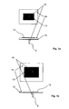
- Fig. 1a and Fig. 1b show schematically each top plan view and bottom side view of a planar antenna with a supply line 10 to the ground reference surface 12, which here represents the first electrical conductor simultaneously.
- the position of the supply line 10 is indicated, although this is not visible in itself in supervision.
- the second electrical conductor 13 is the electromagnetic wave radiating element of the antenna.
- the electroactive polymer 14 is arranged between the first electrical conductor and the second electrical conductor 13, the electroactive polymer 14 is arranged.
- Fig. 1a shows the state of the planar antenna without and Fig. 1b with the application of a second signal to tune the frequency.
- the electroactive polymer is compressed by the field formed between the first electrical conductor and the second electrical conductor 13, so that the distance between the first electrical conductor and the second electrical conductor 13 is reduced.
- the electroactive polymer 14, the second electrical conductor 13, and the ground reference surface 12 constituting the first electrical conductor have expanded in width and length. Both by the extent and by the reduced distance between the first electrical conductor and the second electrical conductor 13, the frequency of the electromagnetic first signal to be radiated or received by the second electrical conductor is changed.
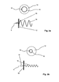
- Fig. 2a and Fig. 2b show each top schematically in plan view and bottom in side view of a helical antenna.
- a supply line 10 is provided to the first electrical conductor, which contacts both the ground reference surface 12 and the first electrical conductor designed as an inner conductor of a coaxial cable.
- the feed line 9 to the second electrical conductor although it would not be visible in the side view in and of themselves, shown in dashed lines and contacted the outer conductor of Coaxial cable, which forms the helix 16 with first and second electrical conductor 13.
- the position of the supply line to the first electrical conductor is indicated in the respective upper figure, although this is not visible in the supervision in and of itself.
- Fig. 2a shows the situation without and Fig.
- the electroactive polymer disposed between the first and second electrical conductors 13 in the helix 16 is compressed and simultaneously stretched. As a result, the pitch and the radius of the helix 16 and thereby also the frequency of the first signal to be radiated or to be received by the second electrical conductor change.
Landscapes
- Details Of Aerials (AREA)
Applications Claiming Priority (1)
| Application Number | Priority Date | Filing Date | Title |
|---|---|---|---|
| DE102011109062 | 2011-07-30 |
Publications (2)
| Publication Number | Publication Date |
|---|---|
| EP2555322A2 true EP2555322A2 (fr) | 2013-02-06 |
| EP2555322A3 EP2555322A3 (fr) | 2013-05-08 |
Family
ID=46581705
Family Applications (1)
| Application Number | Title | Priority Date | Filing Date |
|---|---|---|---|
| EP12005205.5A Withdrawn EP2555322A3 (fr) | 2011-07-30 | 2012-07-14 | Antenne avec polymère électroactif |
Country Status (1)
| Country | Link |
|---|---|
| EP (1) | EP2555322A3 (fr) |
Cited By (1)
| Publication number | Priority date | Publication date | Assignee | Title |
|---|---|---|---|---|
| EP2887449A1 (fr) * | 2013-12-17 | 2015-06-24 | Alcatel Lucent | Filtre à cavité accordable |
Citations (1)
| Publication number | Priority date | Publication date | Assignee | Title |
|---|---|---|---|---|
| WO2009012361A1 (fr) | 2007-07-19 | 2009-01-22 | Rambus Inc. | Antenne de création de faisceau radio avec actionneur polymère électroactif |
Family Cites Families (3)
| Publication number | Priority date | Publication date | Assignee | Title |
|---|---|---|---|---|
| US6597321B2 (en) * | 2001-11-08 | 2003-07-22 | Skycross, Inc. | Adaptive variable impedance transmission line loaded antenna |
| KR20050048164A (ko) * | 2003-11-19 | 2005-05-24 | 학교법인 성균관대학 | 압전소자를 이용한 마이크로스트립 안테나 |
| US20100127953A1 (en) * | 2008-11-25 | 2010-05-27 | Sony Ericsson Mobile Communications Ab | Antenna, antenna arrangement and radio communication apparatus |
-
2012
- 2012-07-14 EP EP12005205.5A patent/EP2555322A3/fr not_active Withdrawn
Patent Citations (1)
| Publication number | Priority date | Publication date | Assignee | Title |
|---|---|---|---|---|
| WO2009012361A1 (fr) | 2007-07-19 | 2009-01-22 | Rambus Inc. | Antenne de création de faisceau radio avec actionneur polymère électroactif |
Cited By (1)
| Publication number | Priority date | Publication date | Assignee | Title |
|---|---|---|---|---|
| EP2887449A1 (fr) * | 2013-12-17 | 2015-06-24 | Alcatel Lucent | Filtre à cavité accordable |
Also Published As
| Publication number | Publication date |
|---|---|
| EP2555322A3 (fr) | 2013-05-08 |
Similar Documents
| Publication | Publication Date | Title |
|---|---|---|
| EP2338207B1 (fr) | Antenne pour balise rfid | |
| DE102016204868B4 (de) | Antennenvorrichtung | |
| EP2784874B1 (fr) | Antenne monopôle à large bande pour deux bandes de fréquences séparées par un écart de fréquence dans la plage d'ondes décimétriques pour des véhicules | |
| EP3178129B1 (fr) | Antenne unipolaire à bande large à structure multiple pour deux bandes de fréquence séparées par un espace blanc dans la plage d'ondes décimétriques, destinée à des véhicules | |
| EP3163690A1 (fr) | Prise mâle comprenant une cage ressort sur le côté raccordement | |
| EP3244483B1 (fr) | Boîtier blindé pour applications hf | |
| DE602005002330T2 (de) | Logarithmisch periodische Mikrostreifengruppenantenne mit geerdetem halbkoplanaren Übergang von Wellenleiter auf Mikrostreifenleitung | |
| EP3082193A1 (fr) | Bloc déphaseur differentiel | |
| DE102011004478B4 (de) | Antenne vom Substrattyp | |
| EP2681063B1 (fr) | Arrangement d'antenne dans un véhicule | |
| EP3232454B1 (fr) | Barre omnibus comprenant une pluralité de condensateurs à film | |
| DE102004045707A1 (de) | Antenne | |
| DE112017002543B4 (de) | Antennenvorrichtung | |
| EP1619751B1 (fr) | Antenne à large bande et à profil bas | |
| WO2016045830A1 (fr) | Antenne pour radar de proximité | |
| EP2367233A1 (fr) | Système d'antenes planaires | |
| EP2555322A2 (fr) | Antenne avec polymère électroactif | |
| EP3096393A1 (fr) | Bloc dephaseur differentiel | |
| DE102014018573A1 (de) | Antennenanordnung mit planarer geschlitzter Patchantenne hoher Bandbreite | |
| DE102019108901A1 (de) | Antennenanordnung für Mobilfunksysteme mit zumindest einem dual-polarisierten Kreuzdipol | |
| DE102017220877A1 (de) | Vorrichtung zum Ableiten eines Schirmstroms eines Leitungsbündels für ein Kraftfahrzeug und Kraftfahrzeug | |
| DE102019109762B4 (de) | Antennensystem, antennensubstrat, und antennenelement | |
| WO1999048168A1 (fr) | Unite d'installation electrique encastree comportant une antenne | |
| WO2012175533A1 (fr) | Système conducteur | |
| DE3238806C2 (de) | Symmetriereinrichtung |
Legal Events
| Date | Code | Title | Description |
|---|---|---|---|
| PUAI | Public reference made under article 153(3) epc to a published international application that has entered the european phase |
Free format text: ORIGINAL CODE: 0009012 |
|
| AK | Designated contracting states |
Kind code of ref document: A2 Designated state(s): AL AT BE BG CH CY CZ DE DK EE ES FI FR GB GR HR HU IE IS IT LI LT LU LV MC MK MT NL NO PL PT RO RS SE SI SK SM TR |
|
| AX | Request for extension of the european patent |
Extension state: BA ME |
|
| PUAL | Search report despatched |
Free format text: ORIGINAL CODE: 0009013 |
|
| AK | Designated contracting states |
Kind code of ref document: A3 Designated state(s): AL AT BE BG CH CY CZ DE DK EE ES FI FR GB GR HR HU IE IS IT LI LT LU LV MC MK MT NL NO PL PT RO RS SE SI SK SM TR |
|
| AX | Request for extension of the european patent |
Extension state: BA ME |
|
| RIC1 | Information provided on ipc code assigned before grant |
Ipc: H01Q 11/08 20060101ALI20130402BHEP Ipc: H01Q 1/36 20060101AFI20130402BHEP Ipc: H01Q 9/04 20060101ALI20130402BHEP |
|
| STAA | Information on the status of an ep patent application or granted ep patent |
Free format text: STATUS: THE APPLICATION IS DEEMED TO BE WITHDRAWN |
|
| 18D | Application deemed to be withdrawn |
Effective date: 20131109 |