EP2555332A1 - Kontaktelement - Google Patents
Kontaktelement Download PDFInfo
- Publication number
- EP2555332A1 EP2555332A1 EP11176130A EP11176130A EP2555332A1 EP 2555332 A1 EP2555332 A1 EP 2555332A1 EP 11176130 A EP11176130 A EP 11176130A EP 11176130 A EP11176130 A EP 11176130A EP 2555332 A1 EP2555332 A1 EP 2555332A1
- Authority
- EP
- European Patent Office
- Prior art keywords
- locking
- contact element
- contact
- connection plate
- elements
- Prior art date
- Legal status (The legal status is an assumption and is not a legal conclusion. Google has not performed a legal analysis and makes no representation as to the accuracy of the status listed.)
- Granted
Links
Images


Classifications
-
- H—ELECTRICITY
- H01—ELECTRIC ELEMENTS
- H01R—ELECTRICALLY-CONDUCTIVE CONNECTIONS; STRUCTURAL ASSOCIATIONS OF A PLURALITY OF MUTUALLY-INSULATED ELECTRICAL CONNECTING ELEMENTS; COUPLING DEVICES; CURRENT COLLECTORS
- H01R11/00—Individual connecting elements providing two or more spaced connecting locations for conductive members which are, or may be, thereby interconnected, e.g. end pieces for wires or cables supported by the wire or cable and having means for facilitating electrical connection to some other wire, terminal, or conductive member, blocks of binding posts
- H01R11/11—End pieces or tapping pieces for wires, supported by the wire and for facilitating electrical connection to some other wire, terminal or conductive member
- H01R11/12—End pieces terminating in an eye, hook, or fork
-
- H—ELECTRICITY
- H01—ELECTRIC ELEMENTS
- H01R—ELECTRICALLY-CONDUCTIVE CONNECTIONS; STRUCTURAL ASSOCIATIONS OF A PLURALITY OF MUTUALLY-INSULATED ELECTRICAL CONNECTING ELEMENTS; COUPLING DEVICES; CURRENT COLLECTORS
- H01R13/00—Details of coupling devices of the kinds covered by groups H01R12/70 or H01R24/00 - H01R33/00
- H01R13/02—Contact members
- H01R13/28—Contacts for sliding cooperation with identically-shaped contact, e.g. for hermaphroditic coupling devices
-
- H—ELECTRICITY
- H01—ELECTRIC ELEMENTS
- H01R—ELECTRICALLY-CONDUCTIVE CONNECTIONS; STRUCTURAL ASSOCIATIONS OF A PLURALITY OF MUTUALLY-INSULATED ELECTRICAL CONNECTING ELEMENTS; COUPLING DEVICES; CURRENT COLLECTORS
- H01R4/00—Electrically-conductive connections between two or more conductive members in direct contact, i.e. touching one another; Means for effecting or maintaining such contact; Electrically-conductive connections having two or more spaced connecting locations for conductors and using contact members penetrating insulation
- H01R4/28—Clamped connections, spring connections
- H01R4/30—Clamped connections, spring connections utilising a screw or nut clamping member
- H01R4/305—Clamped connections, spring connections utilising a screw or nut clamping member having means for facilitating engagement of conductive member or for holding it in position
Definitions
- the invention relates to a contact element for connecting electrical conductors, comprising connection means for electrically connecting the contact element to a conductor of a cable as well as a connection plate for connecting the contact element to a contact element of a further cable, wherein the connection plate has at least one locking element and at least one locking hole and wherein the at least one locking element is formed for engaging in a locking hole of the contact element of the further cable.
- Contact elements often called cable lug, are used in the automotive industry for electrically connecting one or several conductors to a ground connection bolt. These several conductors are generally bundled together to a wire harness.
- the ground connection bolt and the car body, to which the ground connection bolt is connected, may also be called conductors.
- the processes during the manufacture of a wire harness or its transportation or its assembly to the ground connection bolt are hardly standardised and, therefore, prone to error and time consuming, especially then, when each cable lug of each individual conductor of a cable has to be individually connected to the ground connection bolt. Furthermore, the danger exists, that the wires get entangled or that an entanglement of the cables is produced.
- DE 10 2005 061 221 A1 describes a contact element, in which the connection plate forms at least one locking element and at least one locking hole, wherein the at least one locking element is formed for engaging the at least one locking hole of a further contact element.
- a locking between the two contact elements is to be ensured by means of one locking projection on a free end of the locking element.
- the object of the present invention is to provide a contact element, which engagement in a further contact element ensures a secure connection during the assembly processes.
- a contact element for connecting electrical conductors comprising connection means for electrically connecting the contact element to a conductor of a cable as well as a connection plate for connecting the contact element to a contact element of a further cable, wherein the connection plate has at least one locking element and at least one locking hole and wherein the at least one locking element is formed for engaging in a locking hole of the contact element of the further cable, and wherein, furthermore, the at least one locking element has two locking projections, which are effective in opposed directions, for locking with the contact element of the further cable.
- the advantage of this arrangement is, that by means of the several locking projections, a secure locking of the first contact element in a further contact element is ensured.
- an axial as well as a radial fixation of two or more contact elements relative to each other is ensured during the transportation of the wire harness and before connecting the contact elements to a ground connection bolt.
- the contact elements are already pre-positioned and are secured relative to each other by means of this radial and axial fixation, so that the possibility of an undesirable wire entanglement is at least drastically reduced, if not even prevented. All contact elements connected to each other and which represent a type of a packet, can be pushed onto the ground connection bolt at the same time. This also contributes to a reduction of the process duration.
- the locking projections are aligned facing away from each other, i.e. are effective. Generally, however, they can also face each and be effective. Preferably, the locking projections are aligned, when seen in circumferential direction, around a hole in the connection plate, facing away from each other.
- the at least one locking element and the at least one locking hole are arranged on a concentrical circumference around a central hole in the connection plate.
- several locking elements and several locking holes are provided on the concentrical circumference around the hole.
- the locking elements as well as the locking holes are, respectively, arranged diametrically opposite in pairs. More locking holes than locking elements can be provided, so that the contact elements can be positioned and fixed in several angular positions relative to each other.
- the at least one locking element has two locking arms, which project from a plane of the connection plate.
- the locking arms are made integrally from the connection plate by means of stamping and transforming. This structure can be manufactured in a simple manner.
- the locking arms can be formed such, that, respectively, one of the locking projections is arranged at the free end of the locking arms.
- connection elements of the first connection plate are passed through the locking holes of the second connection plate and project from the locking holes from the side of the second connection plate, facing away from the first connection plate.
- a space has to be provided on the third connection plate for the locking elements of the first connection plate, so that these are not again detached from their engagement.
- the locking holes widen at least in the area, in which the locking elements engage, towards the side of the connection plate, which is facing away from the locking elements.
- connection arrangement with at least two contact elements of the above described type, wherein the at least two contact elements are connected to each other, such that, respectively, a locking element of a first of the at least two contact elements is locked in a locking hole of a second of the at least two contact elements.
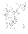
- the contact element 1 consists of a flat connection plate 3 with a central through hole 8, which represents a central opening and by means of which the contact element 1 can be plugged onto a ground connection bolt 11, shown in Fig. 3 .
- Connection means 2 extend in a radial direction from the connection plate 3 in form of a crimping connection, which serves in the present invention for contacting a connection sleeve 12, in which opening 13 a not shown end of an electric conductor of a cable, which insulation is removed at an end, can be accommodated.
- the connection means 2 can also be formed in any other form, e.g. as an insulation displacement contact, a screwed contact or a soldered connection.
- the outer circumference 9 of the connection plate 3 is formed octagonal. Other forms are also possible. Between the outer circumference 9 and the central through hole 8, two locking elements 4, 4' and six locking holes 6 are arranged on a concentrically enlarged circumference around the central through hole 8 or around their geometrical centre. The two locking elements 4, 4' are arranged diametrically to each other. Furthermore, the locking holes 6 are arranged in pairs diametrically to each other. On the respective circumferential portions between the locking elements 4, 4', three locking holes 6 are arranged.
- Each locking element 4, 4' is formed by two locking arms 5, 5', which can be manufactured by stamping and transforming from the connection plate 3 and can project to one side vertically or nearly vertically from the plane of the connection plate. As the locking arms 5, 5' or the locking elements 4, 4' were produced from the connection plate 3, material holes are produced radially within the locking elements 4, 4'.
- the locking arms 5, 5' have, respectively, locking projections 7, 7' in form of projections 16 facing parallel to the connection plate 3.
- the locking projections 7, 7' can simply be formed by means of stamping and transforming.
- the distance of the projection 16 to the upper face of the connection plate 3 is, preferably, a bit larger than the material thickness of the connection plate 3.
- the locking projections 7, 7' of a locking element 4, which consists of two locking arms 5, 5', are aligned facing away from each other. This means, that the locking projections 7, 7' of one locking arm 5, 5' are aligned, when seen in circumferential direction around the central through hole 8 in the connection plate 3, facing away from each other.
- “Aligned facing away from each other” means, that they enclose an obtuse angle between each other, i.e. that the directions, in which the locking projections 7, 7' extend, enclose a right angle or a larger angle.
- a locking element can also have three locking arms, respectively with one locking projection. In a top view onto the locking arms, these are arranged approximately 120 o off-set to each other, i.e. the directions, in which the locking projections extend, enclose an angle of approximately 120o. Thus, the locking projections are aligned facing away from each other.
- a locking element can also have four locking arms, respectively, with one locking projection.
- neighbouring locking arms are arranged offset to each other by 90o concerning the directions, in which the locking projections extend.
- the locking projections of the locking arms which are arranged off-set to each other by 180o, are aligned facing away from each other.
- Fig. 2 two identically formed contact elements 1, 1', locked to each other, are shown, which form a connection arrangement 10.
- the upper contact element 1' is locked relative to the lower contact element 1 such, that the connection means 2 are arranged at an angle to each other.
- the angle off-set is 45o, because of two locking elements 4, 4' and six locking holes 6 which are being uniformly distributed about the circumference. It is visible, that the locking arms 5, 5' of the lower contact element 1 project upwards through the corresponding locking holes 6 of the upper contact element 1'.
- the locking arms 5, 5' slide along angular sliding-slants of the locking projections 7, 7' through the locking holes 6, whereby the two locking arms 5, 5' of a locking element 4 are elastically deformed towards each other, so that they are prebiased.
- the locking projections 7, 7' have reached the upper face of the connection plate 3, the locking arms 5, 5' of a locking element 4 snap because of the pre-biasing, again away from each other and the locking projections 7, 7 lock the two contact elements 1, 1' relative to each other.
- the lower contact element 1 is locked, respectively, via a locking arm 5 by the locking projection 7, i.e. via the projection 16 of the locking arm 5 facing parallel to the plane of the connection plate 3, relative to the connection plate 3, i.e. relative to the upper face of the connection plate 3, of the upper contact element 1'.
- the locking elements of the upper contact element 1' can engage in the locking holes of the further contact element.
- the locking holes 6 are formed such, that they are formed enlarged in the direction towards the respective locking arms 5, 5', by which they are penetrated for locking. At least in the areas, in which the locking arms 5, 5' engage behind the locking holes 6, i.e.
- the locking holes 6, are formed enlarged relative to their extension in circumferential direction. On the narrower side of a locking hole 6, thus, this serves for engaging behind the locking arms 5, 5'. On the wider side of the locking hole 6, the locking arms 5, 5' or the locking projections 7, 7' of a contact element 1, 1' can enter, which is locked to a directly neighbouring contact element 1, 1'.
- the configuration of the locking holes 6 in a longitudinal sectional view is visible in Fig. 4 .
- Fig. 3 shows a connection arrangement 10 consisting of eight contact elements 1, 1' after the plugging onto a ground connection bolt 11.
- the contact elements 1, 1' are secured on the ground connection bolt 11.
- the locking elements 4, 4' and the locking holes 6, distributed evenly about the circumference the contact elements 1, 1' form a star-like arrangement.
- Fig. 5 shows an alternative embodiment of a contact element 1, wherein the locking arms 5, 5' extend not freely radially outwards, but extend radially inwards forming a hole.
- the contact element 1 corresponds to that of Fig. 1 , wherein corresponding features are provided with the same reference numeral.
Landscapes
- Connector Housings Or Holding Contact Members (AREA)
Priority Applications (1)
| Application Number | Priority Date | Filing Date | Title |
|---|---|---|---|
| EP20110176130 EP2555332B1 (de) | 2011-08-01 | 2011-08-01 | Kontaktelement |
Applications Claiming Priority (1)
| Application Number | Priority Date | Filing Date | Title |
|---|---|---|---|
| EP20110176130 EP2555332B1 (de) | 2011-08-01 | 2011-08-01 | Kontaktelement |
Publications (2)
| Publication Number | Publication Date |
|---|---|
| EP2555332A1 true EP2555332A1 (de) | 2013-02-06 |
| EP2555332B1 EP2555332B1 (de) | 2014-03-19 |
Family
ID=45318726
Family Applications (1)
| Application Number | Title | Priority Date | Filing Date |
|---|---|---|---|
| EP20110176130 Not-in-force EP2555332B1 (de) | 2011-08-01 | 2011-08-01 | Kontaktelement |
Country Status (1)
| Country | Link |
|---|---|
| EP (1) | EP2555332B1 (de) |
Cited By (2)
| Publication number | Priority date | Publication date | Assignee | Title |
|---|---|---|---|---|
| FR3028675A1 (fr) * | 2014-11-19 | 2016-05-20 | Renault Sa | Agencement pour empecher la rotation d'une cosse electrique et procede de fabrication correspondant. |
| JP2022049734A (ja) * | 2020-09-17 | 2022-03-30 | 古河電気工業株式会社 | 電線・ケーブルの接続構造 |
Citations (4)
| Publication number | Priority date | Publication date | Assignee | Title |
|---|---|---|---|---|
| EP0670612A1 (de) * | 1994-03-01 | 1995-09-06 | Sumitomo Wiring Systems, Ltd. | Elektrische Anschlussklemme |
| EP0803935A2 (de) * | 1996-04-22 | 1997-10-29 | Sumitomo Wiring Systems, Ltd. | Structur für den Zusammenbau von Anschlussklemmen aus Metall |
| EP1746686A1 (de) * | 2005-07-21 | 2007-01-24 | Delphi Technologies, Inc. | Elektrisches Anschlusselement |
| DE102005061221A1 (de) | 2005-12-20 | 2007-06-28 | Stocko Contact Gmbh & Co. Kg | Elektrisches Kontaktelement |
-
2011
- 2011-08-01 EP EP20110176130 patent/EP2555332B1/de not_active Not-in-force
Patent Citations (4)
| Publication number | Priority date | Publication date | Assignee | Title |
|---|---|---|---|---|
| EP0670612A1 (de) * | 1994-03-01 | 1995-09-06 | Sumitomo Wiring Systems, Ltd. | Elektrische Anschlussklemme |
| EP0803935A2 (de) * | 1996-04-22 | 1997-10-29 | Sumitomo Wiring Systems, Ltd. | Structur für den Zusammenbau von Anschlussklemmen aus Metall |
| EP1746686A1 (de) * | 2005-07-21 | 2007-01-24 | Delphi Technologies, Inc. | Elektrisches Anschlusselement |
| DE102005061221A1 (de) | 2005-12-20 | 2007-06-28 | Stocko Contact Gmbh & Co. Kg | Elektrisches Kontaktelement |
Cited By (2)
| Publication number | Priority date | Publication date | Assignee | Title |
|---|---|---|---|---|
| FR3028675A1 (fr) * | 2014-11-19 | 2016-05-20 | Renault Sa | Agencement pour empecher la rotation d'une cosse electrique et procede de fabrication correspondant. |
| JP2022049734A (ja) * | 2020-09-17 | 2022-03-30 | 古河電気工業株式会社 | 電線・ケーブルの接続構造 |
Also Published As
| Publication number | Publication date |
|---|---|
| EP2555332B1 (de) | 2014-03-19 |
Similar Documents
| Publication | Publication Date | Title |
|---|---|---|
| US8696376B2 (en) | Cable connection system and method for connecting a cable to a cable connection system | |
| EP2664034B1 (de) | Kontaktanordnung für einen elektrischen verbinder | |
| US7125295B2 (en) | Interlocking ring terminals | |
| US8105121B2 (en) | Ground terminal fitting with a clamping section touching a ground member | |
| US20170264025A1 (en) | Plug connector | |
| US20140015359A1 (en) | Buss bar assembly having printed buss bar plates | |
| US20170302130A1 (en) | Motor with wiring board formed by crimp-connecting winding | |
| EP2675019A1 (de) | Erdungsklemmen-Baugruppenkonstruktion und entsprechendes Verfahren | |
| US4357070A (en) | Interlocking electric connectors | |
| US12166312B2 (en) | Housing for an electrical connector | |
| EP3760489A1 (de) | Befestigungskörper für kabel | |
| EP2555332B1 (de) | Kontaktelement | |
| KR102865226B1 (ko) | 포지티브 잠금 요소들을 갖는 고정 슬리브 | |
| US20180034199A1 (en) | Anti-Kink Protection Assembly and Method for Installing the Anti-Kink Protector | |
| JP2012235666A (ja) | コルゲートチューブおよび該コルゲートチューブの取付方法 | |
| CN106972299B (zh) | 接触元件 | |
| JP2010165486A (ja) | 電線接続ユニット | |
| US12080449B2 (en) | Power conductor and system | |
| JP5773218B2 (ja) | 圧着端子 | |
| JP3222628U (ja) | 接点要素及びプラグコネクタ | |
| EP3859895B1 (de) | Zum crimpen vorbereitete crimphülse | |
| US20060270285A1 (en) | Connector assembly and method of making same | |
| CN110050391A (zh) | 线夹盖件 | |
| JP2016149278A (ja) | ワイヤーハーネス | |
| US6142818A (en) | IDC twist cap strain relief |
Legal Events
| Date | Code | Title | Description |
|---|---|---|---|
| PUAI | Public reference made under article 153(3) epc to a published international application that has entered the european phase |
Free format text: ORIGINAL CODE: 0009012 |
|
| AK | Designated contracting states |
Kind code of ref document: A1 Designated state(s): AL AT BE BG CH CY CZ DE DK EE ES FI FR GB GR HR HU IE IS IT LI LT LU LV MC MK MT NL NO PL PT RO RS SE SI SK SM TR |
|
| AX | Request for extension of the european patent |
Extension state: BA ME |
|
| 17P | Request for examination filed |
Effective date: 20130719 |
|
| RBV | Designated contracting states (corrected) |
Designated state(s): AL AT BE BG CH CY CZ DE DK EE ES FI FR GB GR HR HU IE IS IT LI LT LU LV MC MK MT NL NO PL PT RO RS SE SI SK SM TR |
|
| GRAP | Despatch of communication of intention to grant a patent |
Free format text: ORIGINAL CODE: EPIDOSNIGR1 |
|
| RIC1 | Information provided on ipc code assigned before grant |
Ipc: H01R 11/12 20060101AFI20131018BHEP Ipc: H01R 4/30 20060101ALI20131018BHEP Ipc: H01R 13/28 20060101ALI20131018BHEP |
|
| INTG | Intention to grant announced |
Effective date: 20131107 |
|
| GRAS | Grant fee paid |
Free format text: ORIGINAL CODE: EPIDOSNIGR3 |
|
| GRAA | (expected) grant |
Free format text: ORIGINAL CODE: 0009210 |
|
| AK | Designated contracting states |
Kind code of ref document: B1 Designated state(s): AL AT BE BG CH CY CZ DE DK EE ES FI FR GB GR HR HU IE IS IT LI LT LU LV MC MK MT NL NO PL PT RO RS SE SI SK SM TR |
|
| REG | Reference to a national code |
Ref country code: GB Ref legal event code: FG4D |
|
| REG | Reference to a national code |
Ref country code: CH Ref legal event code: EP |
|
| REG | Reference to a national code |
Ref country code: AT Ref legal event code: REF Ref document number: 658204 Country of ref document: AT Kind code of ref document: T Effective date: 20140415 |
|
| REG | Reference to a national code |
Ref country code: IE Ref legal event code: FG4D |
|
| REG | Reference to a national code |
Ref country code: DE Ref legal event code: R096 Ref document number: 602011005428 Country of ref document: DE Effective date: 20140430 |
|
| PG25 | Lapsed in a contracting state [announced via postgrant information from national office to epo] |
Ref country code: LT Free format text: LAPSE BECAUSE OF FAILURE TO SUBMIT A TRANSLATION OF THE DESCRIPTION OR TO PAY THE FEE WITHIN THE PRESCRIBED TIME-LIMIT Effective date: 20140319 Ref country code: NO Free format text: LAPSE BECAUSE OF FAILURE TO SUBMIT A TRANSLATION OF THE DESCRIPTION OR TO PAY THE FEE WITHIN THE PRESCRIBED TIME-LIMIT Effective date: 20140619 |
|
| REG | Reference to a national code |
Ref country code: NL Ref legal event code: VDEP Effective date: 20140319 |
|
| REG | Reference to a national code |
Ref country code: AT Ref legal event code: MK05 Ref document number: 658204 Country of ref document: AT Kind code of ref document: T Effective date: 20140319 |
|
| REG | Reference to a national code |
Ref country code: LT Ref legal event code: MG4D |
|
| PG25 | Lapsed in a contracting state [announced via postgrant information from national office to epo] |
Ref country code: SE Free format text: LAPSE BECAUSE OF FAILURE TO SUBMIT A TRANSLATION OF THE DESCRIPTION OR TO PAY THE FEE WITHIN THE PRESCRIBED TIME-LIMIT Effective date: 20140319 Ref country code: CY Free format text: LAPSE BECAUSE OF FAILURE TO SUBMIT A TRANSLATION OF THE DESCRIPTION OR TO PAY THE FEE WITHIN THE PRESCRIBED TIME-LIMIT Effective date: 20140319 Ref country code: FI Free format text: LAPSE BECAUSE OF FAILURE TO SUBMIT A TRANSLATION OF THE DESCRIPTION OR TO PAY THE FEE WITHIN THE PRESCRIBED TIME-LIMIT Effective date: 20140319 |
|
| PG25 | Lapsed in a contracting state [announced via postgrant information from national office to epo] |
Ref country code: HR Free format text: LAPSE BECAUSE OF FAILURE TO SUBMIT A TRANSLATION OF THE DESCRIPTION OR TO PAY THE FEE WITHIN THE PRESCRIBED TIME-LIMIT Effective date: 20140319 Ref country code: LV Free format text: LAPSE BECAUSE OF FAILURE TO SUBMIT A TRANSLATION OF THE DESCRIPTION OR TO PAY THE FEE WITHIN THE PRESCRIBED TIME-LIMIT Effective date: 20140319 Ref country code: RS Free format text: LAPSE BECAUSE OF FAILURE TO SUBMIT A TRANSLATION OF THE DESCRIPTION OR TO PAY THE FEE WITHIN THE PRESCRIBED TIME-LIMIT Effective date: 20140319 |
|
| PG25 | Lapsed in a contracting state [announced via postgrant information from national office to epo] |
Ref country code: RO Free format text: LAPSE BECAUSE OF FAILURE TO SUBMIT A TRANSLATION OF THE DESCRIPTION OR TO PAY THE FEE WITHIN THE PRESCRIBED TIME-LIMIT Effective date: 20140319 Ref country code: IS Free format text: LAPSE BECAUSE OF FAILURE TO SUBMIT A TRANSLATION OF THE DESCRIPTION OR TO PAY THE FEE WITHIN THE PRESCRIBED TIME-LIMIT Effective date: 20140719 Ref country code: CZ Free format text: LAPSE BECAUSE OF FAILURE TO SUBMIT A TRANSLATION OF THE DESCRIPTION OR TO PAY THE FEE WITHIN THE PRESCRIBED TIME-LIMIT Effective date: 20140319 Ref country code: EE Free format text: LAPSE BECAUSE OF FAILURE TO SUBMIT A TRANSLATION OF THE DESCRIPTION OR TO PAY THE FEE WITHIN THE PRESCRIBED TIME-LIMIT Effective date: 20140319 Ref country code: BG Free format text: LAPSE BECAUSE OF FAILURE TO SUBMIT A TRANSLATION OF THE DESCRIPTION OR TO PAY THE FEE WITHIN THE PRESCRIBED TIME-LIMIT Effective date: 20140619 Ref country code: BE Free format text: LAPSE BECAUSE OF FAILURE TO SUBMIT A TRANSLATION OF THE DESCRIPTION OR TO PAY THE FEE WITHIN THE PRESCRIBED TIME-LIMIT Effective date: 20140319 Ref country code: NL Free format text: LAPSE BECAUSE OF FAILURE TO SUBMIT A TRANSLATION OF THE DESCRIPTION OR TO PAY THE FEE WITHIN THE PRESCRIBED TIME-LIMIT Effective date: 20140319 |
|
| PG25 | Lapsed in a contracting state [announced via postgrant information from national office to epo] |
Ref country code: PL Free format text: LAPSE BECAUSE OF FAILURE TO SUBMIT A TRANSLATION OF THE DESCRIPTION OR TO PAY THE FEE WITHIN THE PRESCRIBED TIME-LIMIT Effective date: 20140319 Ref country code: SK Free format text: LAPSE BECAUSE OF FAILURE TO SUBMIT A TRANSLATION OF THE DESCRIPTION OR TO PAY THE FEE WITHIN THE PRESCRIBED TIME-LIMIT Effective date: 20140319 Ref country code: ES Free format text: LAPSE BECAUSE OF FAILURE TO SUBMIT A TRANSLATION OF THE DESCRIPTION OR TO PAY THE FEE WITHIN THE PRESCRIBED TIME-LIMIT Effective date: 20140319 Ref country code: AT Free format text: LAPSE BECAUSE OF FAILURE TO SUBMIT A TRANSLATION OF THE DESCRIPTION OR TO PAY THE FEE WITHIN THE PRESCRIBED TIME-LIMIT Effective date: 20140319 |
|
| REG | Reference to a national code |
Ref country code: DE Ref legal event code: R097 Ref document number: 602011005428 Country of ref document: DE |
|
| PG25 | Lapsed in a contracting state [announced via postgrant information from national office to epo] |
Ref country code: PT Free format text: LAPSE BECAUSE OF FAILURE TO SUBMIT A TRANSLATION OF THE DESCRIPTION OR TO PAY THE FEE WITHIN THE PRESCRIBED TIME-LIMIT Effective date: 20140721 |
|
| PLBE | No opposition filed within time limit |
Free format text: ORIGINAL CODE: 0009261 |
|
| STAA | Information on the status of an ep patent application or granted ep patent |
Free format text: STATUS: NO OPPOSITION FILED WITHIN TIME LIMIT |
|
| PG25 | Lapsed in a contracting state [announced via postgrant information from national office to epo] |
Ref country code: DK Free format text: LAPSE BECAUSE OF FAILURE TO SUBMIT A TRANSLATION OF THE DESCRIPTION OR TO PAY THE FEE WITHIN THE PRESCRIBED TIME-LIMIT Effective date: 20140319 |
|
| 26N | No opposition filed |
Effective date: 20141222 |
|
| PG25 | Lapsed in a contracting state [announced via postgrant information from national office to epo] |
Ref country code: MC Free format text: LAPSE BECAUSE OF FAILURE TO SUBMIT A TRANSLATION OF THE DESCRIPTION OR TO PAY THE FEE WITHIN THE PRESCRIBED TIME-LIMIT Effective date: 20140319 Ref country code: LU Free format text: LAPSE BECAUSE OF FAILURE TO SUBMIT A TRANSLATION OF THE DESCRIPTION OR TO PAY THE FEE WITHIN THE PRESCRIBED TIME-LIMIT Effective date: 20140801 Ref country code: IT Free format text: LAPSE BECAUSE OF FAILURE TO SUBMIT A TRANSLATION OF THE DESCRIPTION OR TO PAY THE FEE WITHIN THE PRESCRIBED TIME-LIMIT Effective date: 20140319 |
|
| REG | Reference to a national code |
Ref country code: CH Ref legal event code: PL |
|
| REG | Reference to a national code |
Ref country code: DE Ref legal event code: R097 Ref document number: 602011005428 Country of ref document: DE Effective date: 20141222 |
|
| PG25 | Lapsed in a contracting state [announced via postgrant information from national office to epo] |
Ref country code: LI Free format text: LAPSE BECAUSE OF NON-PAYMENT OF DUE FEES Effective date: 20140831 Ref country code: CH Free format text: LAPSE BECAUSE OF NON-PAYMENT OF DUE FEES Effective date: 20140831 |
|
| REG | Reference to a national code |
Ref country code: IE Ref legal event code: MM4A |
|
| PG25 | Lapsed in a contracting state [announced via postgrant information from national office to epo] |
Ref country code: SI Free format text: LAPSE BECAUSE OF FAILURE TO SUBMIT A TRANSLATION OF THE DESCRIPTION OR TO PAY THE FEE WITHIN THE PRESCRIBED TIME-LIMIT Effective date: 20140319 |
|
| PG25 | Lapsed in a contracting state [announced via postgrant information from national office to epo] |
Ref country code: IE Free format text: LAPSE BECAUSE OF NON-PAYMENT OF DUE FEES Effective date: 20140801 |
|
| PG25 | Lapsed in a contracting state [announced via postgrant information from national office to epo] |
Ref country code: SM Free format text: LAPSE BECAUSE OF FAILURE TO SUBMIT A TRANSLATION OF THE DESCRIPTION OR TO PAY THE FEE WITHIN THE PRESCRIBED TIME-LIMIT Effective date: 20140319 |
|
| PG25 | Lapsed in a contracting state [announced via postgrant information from national office to epo] |
Ref country code: GR Free format text: LAPSE BECAUSE OF FAILURE TO SUBMIT A TRANSLATION OF THE DESCRIPTION OR TO PAY THE FEE WITHIN THE PRESCRIBED TIME-LIMIT Effective date: 20140620 Ref country code: MT Free format text: LAPSE BECAUSE OF FAILURE TO SUBMIT A TRANSLATION OF THE DESCRIPTION OR TO PAY THE FEE WITHIN THE PRESCRIBED TIME-LIMIT Effective date: 20140319 |
|
| PG25 | Lapsed in a contracting state [announced via postgrant information from national office to epo] |
Ref country code: TR Free format text: LAPSE BECAUSE OF FAILURE TO SUBMIT A TRANSLATION OF THE DESCRIPTION OR TO PAY THE FEE WITHIN THE PRESCRIBED TIME-LIMIT Effective date: 20140319 Ref country code: HU Free format text: LAPSE BECAUSE OF FAILURE TO SUBMIT A TRANSLATION OF THE DESCRIPTION OR TO PAY THE FEE WITHIN THE PRESCRIBED TIME-LIMIT; INVALID AB INITIO Effective date: 20110801 |
|
| REG | Reference to a national code |
Ref country code: FR Ref legal event code: PLFP Year of fee payment: 6 |
|
| REG | Reference to a national code |
Ref country code: FR Ref legal event code: PLFP Year of fee payment: 7 |
|
| PG25 | Lapsed in a contracting state [announced via postgrant information from national office to epo] |
Ref country code: MK Free format text: LAPSE BECAUSE OF FAILURE TO SUBMIT A TRANSLATION OF THE DESCRIPTION OR TO PAY THE FEE WITHIN THE PRESCRIBED TIME-LIMIT Effective date: 20140319 |
|
| REG | Reference to a national code |
Ref country code: FR Ref legal event code: PLFP Year of fee payment: 8 |
|
| PG25 | Lapsed in a contracting state [announced via postgrant information from national office to epo] |
Ref country code: AL Free format text: LAPSE BECAUSE OF FAILURE TO SUBMIT A TRANSLATION OF THE DESCRIPTION OR TO PAY THE FEE WITHIN THE PRESCRIBED TIME-LIMIT Effective date: 20140319 |
|
| PGFP | Annual fee paid to national office [announced via postgrant information from national office to epo] |
Ref country code: FR Payment date: 20190822 Year of fee payment: 9 Ref country code: DE Payment date: 20190822 Year of fee payment: 9 |
|
| PGFP | Annual fee paid to national office [announced via postgrant information from national office to epo] |
Ref country code: GB Payment date: 20190827 Year of fee payment: 9 |
|
| REG | Reference to a national code |
Ref country code: DE Ref legal event code: R119 Ref document number: 602011005428 Country of ref document: DE |
|
| GBPC | Gb: european patent ceased through non-payment of renewal fee |
Effective date: 20200801 |
|
| PG25 | Lapsed in a contracting state [announced via postgrant information from national office to epo] |
Ref country code: FR Free format text: LAPSE BECAUSE OF NON-PAYMENT OF DUE FEES Effective date: 20200831 Ref country code: DE Free format text: LAPSE BECAUSE OF NON-PAYMENT OF DUE FEES Effective date: 20210302 |
|
| PG25 | Lapsed in a contracting state [announced via postgrant information from national office to epo] |
Ref country code: GB Free format text: LAPSE BECAUSE OF NON-PAYMENT OF DUE FEES Effective date: 20200801 |