EP2555366A2 - Dispositif d'interception, de préférence pour câble haute tension - Google Patents
Dispositif d'interception, de préférence pour câble haute tension Download PDFInfo
- Publication number
- EP2555366A2 EP2555366A2 EP12005660A EP12005660A EP2555366A2 EP 2555366 A2 EP2555366 A2 EP 2555366A2 EP 12005660 A EP12005660 A EP 12005660A EP 12005660 A EP12005660 A EP 12005660A EP 2555366 A2 EP2555366 A2 EP 2555366A2
- Authority
- EP
- European Patent Office
- Prior art keywords
- ring
- outer ring
- core ring
- platform
- core
- Prior art date
- Legal status (The legal status is an assumption and is not a legal conclusion. Google has not performed a legal analysis and makes no representation as to the accuracy of the status listed.)
- Granted
Links
- 230000003014 reinforcing effect Effects 0.000 claims description 30
- 230000001419 dependent effect Effects 0.000 claims description 3
- 229940004975 interceptor Drugs 0.000 claims 2
- 230000002787 reinforcement Effects 0.000 abstract description 7
- 230000035882 stress Effects 0.000 description 3
- 229910000831 Steel Inorganic materials 0.000 description 2
- 238000010276 construction Methods 0.000 description 2
- 238000011161 development Methods 0.000 description 2
- 230000018109 developmental process Effects 0.000 description 2
- 239000011521 glass Substances 0.000 description 2
- 238000009434 installation Methods 0.000 description 2
- 239000010959 steel Substances 0.000 description 2
- 238000005452 bending Methods 0.000 description 1
- 230000015572 biosynthetic process Effects 0.000 description 1
- 230000003750 conditioning effect Effects 0.000 description 1
- 239000004020 conductor Substances 0.000 description 1
- 230000007797 corrosion Effects 0.000 description 1
- 238000005260 corrosion Methods 0.000 description 1
- 230000002349 favourable effect Effects 0.000 description 1
- 238000009413 insulation Methods 0.000 description 1
- 230000002427 irreversible effect Effects 0.000 description 1
- 230000001681 protective effect Effects 0.000 description 1
- 238000007789 sealing Methods 0.000 description 1
- 239000007787 solid Substances 0.000 description 1
- 230000002459 sustained effect Effects 0.000 description 1
- 230000008646 thermal stress Effects 0.000 description 1
- XLYOFNOQVPJJNP-UHFFFAOYSA-N water Substances O XLYOFNOQVPJJNP-UHFFFAOYSA-N 0.000 description 1
Images

Classifications
-
- H—ELECTRICITY
- H02—GENERATION; CONVERSION OR DISTRIBUTION OF ELECTRIC POWER
- H02G—INSTALLATION OF ELECTRIC CABLES OR LINES, OR OF COMBINED OPTICAL AND ELECTRIC CABLES OR LINES
- H02G15/00—Cable fittings
- H02G15/02—Cable terminations
- H02G15/06—Cable terminating boxes, frames or other structures
-
- H—ELECTRICITY
- H02—GENERATION; CONVERSION OR DISTRIBUTION OF ELECTRIC POWER
- H02G—INSTALLATION OF ELECTRIC CABLES OR LINES, OR OF COMBINED OPTICAL AND ELECTRIC CABLES OR LINES
- H02G15/00—Cable fittings
- H02G15/08—Cable junctions
- H02G15/10—Cable junctions protected by boxes, e.g. by distribution, connection or junction boxes
- H02G15/12—Cable junctions protected by boxes, e.g. by distribution, connection or junction boxes for incorporating transformers, loading coils or amplifiers
- H02G15/14—Cable junctions protected by boxes, e.g. by distribution, connection or junction boxes for incorporating transformers, loading coils or amplifiers specially adapted for submarine cables
-
- H—ELECTRICITY
- H02—GENERATION; CONVERSION OR DISTRIBUTION OF ELECTRIC POWER
- H02G—INSTALLATION OF ELECTRIC CABLES OR LINES, OR OF COMBINED OPTICAL AND ELECTRIC CABLES OR LINES
- H02G9/00—Installations of electric cables or lines in or on the ground or water
- H02G9/12—Installations of electric cables or lines in or on the ground or water supported on or from floats, e.g. in water
Definitions
- the invention relates to an interceptor for a guided through the bottom of an opening of a horizontal platform, formed with a reinforcing layer, free-hanging object, in particular for a power cable.
- a puller head is used to engage the armor layer of the power cable and pick up the weight of the hanging cable.
- the mechanical tensile forces are absorbed by the reinforcing layer, with as few forces as possible being transmitted to the inner cable structure.
- the power cable is fixed by means of a temporary or a permanent cable-catching device (English 'hang-off').
- the DE 1042063 B describes an interceptor for an overseas cable with a large number of individual segments.
- the device has the goal to clamp all reinforcement wires as possible with the same tensile stress. Therefore, the structure consists of many parts and the assembly is accordingly very expensive.
- the font US 2006-0193572 A1 shows an interceptor for a bottomed through an opening data cable with clamping means for a reinforcing layer and supporting means for supporting the device on a platform. Further details can not be found in the text.
- the reinforcing wires are widened conically and bent over a ring. Bending occurs from the larger diameter of the widening inward towards the cable surface.
- the reinforcing wires are finally permanently clamped between two conically and mutually matching clamping means and a cover plate and thus mechanically secured the cable ( US 2010-0314151 A1 ).
- Narrow clamping cables and trapping means which are made of steel and usually made of steel, have the disadvantage that during operation of the cable, magnetic losses occur which lead to power losses and thermal stress on the cable in the area of the support.
- sealing arrangements published for the passage of an electric cable into a submerged apparatus housing.
- a first example shows the GB 1571679 A in which one or two layers of reinforcing elements are used.
- Another example is from the DE 832009 B known. These arrangements are used to seal against a prevailing pressure under water.
- the strain relief or interception of the cable weight is achieved with many items that are fixed together.
- the clamping comes about by the expended forces in the screwing of the individual parts. A control of the clamping forces to avoid excessive deformation of the reinforcing elements is not provided.
- the reinforcing elements are wrapped around the core ring from the inner surface of a core ring to the outer surface of the core ring.
- the invention has for its object to provide an interception device that is easy to assemble and disassemble and in which the reinforcing elements are braced as gently as possible.
- the interceptor consists of only a few individual parts, of which an outer ring and support means are connected directly or indirectly fixedly to the platform, and a core or inner ring wrapped by Arm michsdrähten lying alone in the pulling direction of the elongated object in the outer ring in automatic clamping contact and holding function of Arm michsdrähte with the outer ring is.
- the weight of the object is absorbed by a (temporary) holding means.
- the article is pulled from below through an opening of the platform up and held.
- the reinforcing wires are wrapped around the core ring and received by releasing the holding means from the outer ring by clamping.
- clamping When clamping the full tensile load from the holding means on the interceptor over. Due to the tensile force of the free-hanging object core ring and outer ring are pressed together. The clamping is thus zugkrafttouch.
- the weight of the elongated object received by the intercepting device is taken over by a (temporary) device, thus relieving the intercepting device of its full weight.
- the tensile load is practically zero, whereby the clamping between the core ring and outer ring dissolves.
- the fixing elements of the interceptor can be removed.
- the weight of the article can be picked up on the now exposed armor wires.
- the system automatically adapts to changing load conditions.
- the clamping is dependent on the glass.
- the outer ring is fixed on the support means (Fixierklalen) in its position.
- the holding force remains the same.
- a pre-damage to the reinforcing wires by applying the clamping forces via tools is excluded.
- the interceptor is proposed for an elongate object formed from below through an opening of a horizontal platform and formed with a reinforcing layer.
- the object develops its traction by its own weight perpendicular to the platform.
- the interceptor comprises armor layer clamping means and support means for supporting the interceptor on the platform.
- the clamping means comprise a core ring, which surrounds the article and is surrounded by elements of the reinforcing layer, which abuts the reinforcing layer, and further connected to the platform via supporting means firmly connected, surrounding the object outer ring.
- the core ring is received in the pulling direction of the object from the outer ring.
- the interceptor may be formed with preferred embodiments.
- the features of the invention mentioned below may be used individually or together in various developments.
- the formation of the core ring as a torus, preferably with elliptical cross-section is essential.
- the reinforcement attempts to change its fixed shape from a large radius of curvature to a small radius of curvature and again to a large radius of curvature. This costs energy, which must be charged to the nip.
- the inner surface of the outer ring is formed such that the core ring in the pulling direction of the article in the outer ring can be inserted.
- the largest dimension of the core ring diameter is greater than the smallest dimension of the inner diameter of the outer ring. The core ring can not slip through the outer ring.
- the core ring is present as a torus, whereby its outer surface is convex.
- the torus may have an elliptical cross-section with the major axis of the ellipse being parallel to the axis of the article.
- a relation between 1.5: 1 and 2: 1 can be selected, for example a ratio of 1.7: 1.
- the surface of the core ring can be provided with grooves or grooves that there is an increased stiction between Arm mich distrdrähten and core ring.
- the reinforcing elements exposed from the reinforcing layer are laid over the core ring and returned against their original orientation.
- the wrapping of the reinforcing elements around the core ring is more than 180 °.
- the reinforcing elements come to lie between an outer surface of the core ring and an inner surface of the outer ring. The clamping arises after release of the temporarily carried object and is thus karkraftpin.
- the inner surface of the outer ring should be formed like a shell for receiving the core ring, wherein preferably the inner surface of the outer ring is conically widening in the direction of the located above the platform end of the article is formed.
- the conical expansion should be within an angular range of 6 ° to 12 °.
- the lying between the generatrices of the cone half angle is meant.
- the outer ring should have holes for synchronbefest only with the support means.
- Core ring and outer ring are formed from at least two identical segment elements.
- the respective rings are wrapped around the elongated object from the outside, wherein they can not be formed as a solid ring, but from parts of the respective ring, preferably namely identical segment elements.
- the elements each comprise a circular sector of 120 °.
- the segment elements of the core ring preferably consist of three ring elements with an elliptical cross-section. These ring elements are connected by three Unterschraubemia, whereby a full ring is formed, whose body has the elliptical cross section, and wherein the major axis of the ellipse is parallel to the axis of the elongated object.
- the segment elements of the outer ring preferably consist of three ring segments, which are screwed against each other via flanges.
- the interception device can be raised and secured directly in the region of a platform opening on the platform.
- a base plate provided with a bore for the passage of the article can be fastened on the opening of the platform.
- the base plate should have holes for the screw fastening with the support means.
- the support means may be in the form of a plurality of fixing columns or in the form of part-cylindrical fixing plates or fixing shells.
- the support means preferably have foot side and head side holes for receiving screws for screwing to the platform, or with the base plate and for receiving screws for screwing to the outer ring.
- the present invention is not limited to the embodiments described above, but also includes all the same in the context of the invention embodiments.
- the invention can also be used for pipes or pipelines reinforced with reinforcing wires.
- the presentation of the invention with particular emphasis on a cable clamp does not mean that the interceptor is limited only for use on power cables.
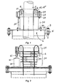
- the Fig. 1 shows a sectional view of the permanent interceptor and Fig. 2 a sectional view of a temporary interceptor.
- the properties and function of the interceptor will be described below using the example of a power cable. In this case, further existing structural elements of the power cable, such as cable wires or cable sheath are not described in detail.
- the power cable for example a 3-core submarine cable 5
- the power cable is 'touched' on the (exposed) armor 6 (on the armor wires) by means of a puller head (not shown and unspecified) and from below through the opening of the platform up onto the horizontal platform 2 pulled and held.
- the power cable may be routed below the opening in a vertical tube.
- a base plate 3 is screwed, which contains 30 prepared holes 4 'for further attachment of the support elements.
- a circular bore 4 for the passage of the power cable.
- a temporary clamping device 50 is attached (see Fig. 2 ).
- This consists according to Fig. 2 of three pairs of half-shells 51, which are wrapped around the cable in the area of the exposed reinforcement and fixed to bolting flanges.
- the half shells have a larger outer diameter than the bore 4 in the base plate 3, so that upon relief of the held cable, the temporary formed from the half shells Clamping device can be placed on the base plate. The load on the pulling head can then be absorbed by the temporary clamping device 50.
- this temporary interception is intended to be temporary because sustained pressure during operation of the cable which catches the load of the suspended power cable can result in irreversible damage to the sheath, insulation and conductors of the power cable.
- the reinforcing wires 6 released by the pulling head are shortened to a suitable length.
- the core ring 10 which is made up of three segments 10 '", is placed just above the temporary clamping device around the cable 10.
- the core ring 10 has a slightly larger inside diameter than the cable in its area, no load or clamping on the cable takes place Now bent over the elliptical cross section of the core ring so far that the ends of the wires again point to the cable surface.
- the armouring wires are so far plastically deformable that they are bent all around the core ring (with an angle of more than 180 °) and there without further holding means take their position.
- a suitable number of hydraulic jacks for example, three jacks 60 with a lifting capacity of about 10 tons
- a suitable number of hydraulic jacks for example, three jacks 60 with a lifting capacity of about 10 tons
- Fixierchulen 30 are mounted from below under the outer ring 20.
- the outer ring has holes which serve the screw connection with the head-side bottles 33 of Fixierchulen.
- the hydraulic lifters are lowered, so that the screw holes on the foot parts 34 of the Fixierchulen 30 come to rest on matching holes in the base plate 3. In this position, the fixing columns 30 are screwed to the base plate 3.
- Fixierchulen 30 may be provided, if not to be expected with large lateral forces. In the event that higher lateral forces are to be expected, the installation of Fixieräulen can be supplemented with other plates (or shells), which are arranged between the Fixierchulen. This leads in cross section to a honeycomb structure, which can then absorb high lateral forces. However, you can also from the outset, instead of the illustrated Fixierchulen large, cylindrical shaped fixing plates 51 used to avoid subsequent reinforcement by other elements.
- the load of the hanging cable takes over the core ring 10 via the Arm michsdrähte 6, via the outer ring 20 and passes over the Fixierklalen 30.
- the introduction of force opens on the base plate 3, or on the platform 2.
- the hydraulic lifts can be removed.
- a protective cover can be provided, which can be placed on the assembly.
- the FIG. 3 shows the outer ring in section and supervision.
- the outer ring 20 consists of three equal segments, each comprising a circular sector of 120 °.
- bores 25 for screw mounting with the support means (on the head flange of Fixierciclen).
- the Fig. 3 still shows the angle W.
- the conical (conical) expansion preferably has an angle of 10 °.
- the cone angle is twice the angle W, namely the angle lying between the generatrices of the cone.
- the FIG. 4 shows the core ring in section and top view.
- the core ring 10 is like the outer ring divided into three parts.
- the core ring 10 is constructed in two parts with respect to its ring plane.
- the torus consists of three identical ring segments.
- Below the ring plane are three Unterlegsegmente (Schschraub comprise 11), which can be screwed to the Toruselementen.
- the core ring diameter 12 is larger than the inner diameter 22 of the outer ring. The core ring can not slip through the outer ring.
- Fixierchulen 30 have each head-side 33 and foot-side flanges 34 for screwing to the base plate or with the platform.
- the advantage of the small number of items comes into play, as well as the fact that the core ring is inserted without fasteners in the outer ring.
- the power cable 5 is 'handled' by means of a pulling head and raised and held upwards.
- the clamping between the core ring 10 and outer ring 20 loosens and dissolves.
- the fixing elements 30 and 51 can be removed.
- the weight of the power cable can be resumed on the now exposed Arm istsdrähten 6.
- all surfaces of the interception device can be treated protected against corrosion.
Landscapes
- Engineering & Computer Science (AREA)
- Power Engineering (AREA)
- Electric Cable Installation (AREA)
- Laying Of Electric Cables Or Lines Outside (AREA)
- Clamps And Clips (AREA)
- Installation Of Indoor Wiring (AREA)
- Vibration Prevention Devices (AREA)
Applications Claiming Priority (1)
| Application Number | Priority Date | Filing Date | Title |
|---|---|---|---|
| DE201110109328 DE102011109328B3 (de) | 2011-08-03 | 2011-08-03 | Abfangvorrichtung, vorzugsweise für Starkstromkabel |
Publications (3)
| Publication Number | Publication Date |
|---|---|
| EP2555366A2 true EP2555366A2 (fr) | 2013-02-06 |
| EP2555366A3 EP2555366A3 (fr) | 2014-02-19 |
| EP2555366B1 EP2555366B1 (fr) | 2015-07-15 |
Family
ID=46801272
Family Applications (1)
| Application Number | Title | Priority Date | Filing Date |
|---|---|---|---|
| EP12005660.1A Not-in-force EP2555366B1 (fr) | 2011-08-03 | 2012-08-03 | Dispositif d'interception, de préférence pour câble haute tension |
Country Status (4)
| Country | Link |
|---|---|
| EP (1) | EP2555366B1 (fr) |
| DE (1) | DE102011109328B3 (fr) |
| DK (1) | DK2555366T3 (fr) |
| ES (1) | ES2546875T3 (fr) |
Families Citing this family (3)
| Publication number | Priority date | Publication date | Assignee | Title |
|---|---|---|---|---|
| DE202016103896U1 (de) | 2016-07-19 | 2016-10-21 | Ams Gmbh | Befestigungseinrichtung für eine Leitung |
| NL2025114B1 (en) * | 2020-03-12 | 2021-10-20 | Vos Prodect Innovations B V | Cable hang-off device |
| CN114865801B (zh) * | 2022-05-18 | 2024-07-02 | 华北电力大学 | 一种用于三芯电缆的高能量密度磁场能量收集装置及系统 |
Citations (5)
| Publication number | Priority date | Publication date | Assignee | Title |
|---|---|---|---|---|
| DE832009C (de) | 1948-03-22 | 1952-02-18 | Telegraph Constr & Maintenance | Kabelabdichtung |
| DE1042063B (de) | 1957-08-09 | 1958-10-30 | Felten & Guilleaume Carlswerk | Abfangvorrichtung fuer die Bewehrung von elektrischen Kabeln |
| GB1571679A (en) | 1978-04-13 | 1980-07-16 | Standard Telephones Cables Ltd | Terminating armoured cables |
| US20060193572A1 (en) | 2005-02-11 | 2006-08-31 | Einar Mjelstad | Power umbilical for deep water |
| US20100314151A1 (en) | 2009-06-15 | 2010-12-16 | Peter William Worrall | Cable termination system |
Family Cites Families (4)
| Publication number | Priority date | Publication date | Assignee | Title |
|---|---|---|---|---|
| US3855414A (en) * | 1973-04-24 | 1974-12-17 | Anaconda Co | Cable armor clamp |
| US4259543A (en) * | 1978-02-07 | 1981-03-31 | International Telephone And Telegraph Corporation | Cable termination |
| US8829347B2 (en) * | 2008-05-30 | 2014-09-09 | Technip France | Power umbilical |
| GB2476655B (en) * | 2009-12-30 | 2014-03-19 | Jdr Cable Systems Ltd | Cable termination system |
-
2011
- 2011-08-03 DE DE201110109328 patent/DE102011109328B3/de not_active Expired - Fee Related
-
2012
- 2012-08-03 ES ES12005660.1T patent/ES2546875T3/es active Active
- 2012-08-03 EP EP12005660.1A patent/EP2555366B1/fr not_active Not-in-force
- 2012-08-03 DK DK12005660.1T patent/DK2555366T3/en active
Patent Citations (5)
| Publication number | Priority date | Publication date | Assignee | Title |
|---|---|---|---|---|
| DE832009C (de) | 1948-03-22 | 1952-02-18 | Telegraph Constr & Maintenance | Kabelabdichtung |
| DE1042063B (de) | 1957-08-09 | 1958-10-30 | Felten & Guilleaume Carlswerk | Abfangvorrichtung fuer die Bewehrung von elektrischen Kabeln |
| GB1571679A (en) | 1978-04-13 | 1980-07-16 | Standard Telephones Cables Ltd | Terminating armoured cables |
| US20060193572A1 (en) | 2005-02-11 | 2006-08-31 | Einar Mjelstad | Power umbilical for deep water |
| US20100314151A1 (en) | 2009-06-15 | 2010-12-16 | Peter William Worrall | Cable termination system |
Also Published As
| Publication number | Publication date |
|---|---|
| DK2555366T3 (en) | 2015-10-05 |
| ES2546875T3 (es) | 2015-09-29 |
| EP2555366A3 (fr) | 2014-02-19 |
| EP2555366B1 (fr) | 2015-07-15 |
| DE102011109328B3 (de) | 2012-12-27 |
Similar Documents
| Publication | Publication Date | Title |
|---|---|---|
| EP2577058B1 (fr) | Mât pour éolienne | |
| DE102014108696A1 (de) | Kompression eines Statorkerns | |
| EP2555366B1 (fr) | Dispositif d'interception, de préférence pour câble haute tension | |
| WO2016142227A1 (fr) | Dispositif support pour modules solaires, installation photovoltaïque présentant plusieurs dispositifs support et procédé pour installer un tel dispositif support | |
| EP2541560A1 (fr) | Câble de supraconducteur | |
| DE1047893B (de) | Feldabstandhalter fuer elektrische Buendelleiter | |
| EP3471223A1 (fr) | Outil de montage destiné au montage et / ou soudage d'une tête de traction de câble à ou d'un câble électrique, en particulier câble sous-marin | |
| EP2546545A2 (fr) | Dispositif de fixation d'un élément de traction, notamment d'une corde de traction | |
| DE202008010908U1 (de) | Vogelabweiser | |
| EP2916407A1 (fr) | Procédé de fermeture résistante à la traction de l'extrémité d'un câble d'énergie et dispositif ainsi fabriqué | |
| EP4006398B1 (fr) | Espaceur pour tuyaux | |
| EP3975358B1 (fr) | Support pour porter des cables, des câbles préférables à haute tension | |
| DE102021120506A1 (de) | Kraftaufnehmer, geotechnisches Ankersystem sowie Verfahren zur Kraftmessung bei einem solchen Ankersystem | |
| DE202016103896U1 (de) | Befestigungseinrichtung für eine Leitung | |
| EP3217494B1 (fr) | Support pour porter des cables, des câbles préférables à haute tension | |
| EP3113310A1 (fr) | Borne pour cable et son procede de fabrication | |
| DE1665699A1 (de) | Verfahren zum Verlegen von Hochspannungskabeln bei UEberwindung grosser Hoehendifferenzen | |
| DE202007015697U1 (de) | Befestigungsvorrichtung für ein Gerüst | |
| CH363692A (de) | Nachgiebiger Abstandhalter für Freileitungen | |
| DE102012019368A1 (de) | Korrekturelement für die Errichtung einer Gründung im Offshore-Bereich sowie Gründungssystem und Verfahren zur Errichtung einer solchen Gründung | |
| EP2251936B1 (fr) | Borne de dérivation pour câble | |
| EP2966224A1 (fr) | Dispositif d'ecartement pour un assemblage de cables de pont | |
| DE3902477C1 (en) | Outer conductor coupling for coaxial cables | |
| DE681790C (de) | Kabel fuer ortsbewegliche Fernmeldeanlagen | |
| AT249150B (de) | Stütze für insbesondere in Fernsprechzentralen verlegte Kabelbündel |
Legal Events
| Date | Code | Title | Description |
|---|---|---|---|
| PUAI | Public reference made under article 153(3) epc to a published international application that has entered the european phase |
Free format text: ORIGINAL CODE: 0009012 |
|
| AK | Designated contracting states |
Kind code of ref document: A2 Designated state(s): AL AT BE BG CH CY CZ DE DK EE ES FI FR GB GR HR HU IE IS IT LI LT LU LV MC MK MT NL NO PL PT RO RS SE SI SK SM TR |
|
| AX | Request for extension of the european patent |
Extension state: BA ME |
|
| PUAL | Search report despatched |
Free format text: ORIGINAL CODE: 0009013 |
|
| AK | Designated contracting states |
Kind code of ref document: A3 Designated state(s): AL AT BE BG CH CY CZ DE DK EE ES FI FR GB GR HR HU IE IS IT LI LT LU LV MC MK MT NL NO PL PT RO RS SE SI SK SM TR |
|
| AX | Request for extension of the european patent |
Extension state: BA ME |
|
| RIC1 | Information provided on ipc code assigned before grant |
Ipc: H02G 15/06 20060101ALI20140116BHEP Ipc: H02G 15/14 20060101ALI20140116BHEP Ipc: H02G 9/12 20060101AFI20140116BHEP |
|
| 17P | Request for examination filed |
Effective date: 20140331 |
|
| RBV | Designated contracting states (corrected) |
Designated state(s): AL AT BE BG CH CY CZ DE DK EE ES FI FR GB GR HR HU IE IS IT LI LT LU LV MC MK MT NL NO PL PT RO RS SE SI SK SM TR |
|
| RAP1 | Party data changed (applicant data changed or rights of an application transferred) |
Owner name: NKT CABLES GMBH & CO. KG |
|
| GRAP | Despatch of communication of intention to grant a patent |
Free format text: ORIGINAL CODE: EPIDOSNIGR1 |
|
| INTG | Intention to grant announced |
Effective date: 20150212 |
|
| GRAS | Grant fee paid |
Free format text: ORIGINAL CODE: EPIDOSNIGR3 |
|
| GRAA | (expected) grant |
Free format text: ORIGINAL CODE: 0009210 |
|
| AK | Designated contracting states |
Kind code of ref document: B1 Designated state(s): AL AT BE BG CH CY CZ DE DK EE ES FI FR GB GR HR HU IE IS IT LI LT LU LV MC MK MT NL NO PL PT RO RS SE SI SK SM TR |
|
| REG | Reference to a national code |
Ref country code: CH Ref legal event code: EP Ref country code: GB Ref legal event code: FG4D Free format text: NOT ENGLISH |
|
| REG | Reference to a national code |
Ref country code: IE Ref legal event code: FG4D Free format text: LANGUAGE OF EP DOCUMENT: GERMAN |
|
| REG | Reference to a national code |
Ref country code: AT Ref legal event code: REF Ref document number: 737209 Country of ref document: AT Kind code of ref document: T Effective date: 20150815 |
|
| REG | Reference to a national code |
Ref country code: DE Ref legal event code: R096 Ref document number: 502012003773 Country of ref document: DE |
|
| REG | Reference to a national code |
Ref country code: ES Ref legal event code: FG2A Ref document number: 2546875 Country of ref document: ES Kind code of ref document: T3 Effective date: 20150929 |
|
| REG | Reference to a national code |
Ref country code: DK Ref legal event code: T3 Effective date: 20150929 |
|
| REG | Reference to a national code |
Ref country code: SE Ref legal event code: TRGR |
|
| REG | Reference to a national code |
Ref country code: NL Ref legal event code: FP |
|
| REG | Reference to a national code |
Ref country code: NO Ref legal event code: T2 Effective date: 20150715 |
|
| REG | Reference to a national code |
Ref country code: LT Ref legal event code: MG4D |
|
| PG25 | Lapsed in a contracting state [announced via postgrant information from national office to epo] |
Ref country code: FI Free format text: LAPSE BECAUSE OF FAILURE TO SUBMIT A TRANSLATION OF THE DESCRIPTION OR TO PAY THE FEE WITHIN THE PRESCRIBED TIME-LIMIT Effective date: 20150715 Ref country code: GR Free format text: LAPSE BECAUSE OF FAILURE TO SUBMIT A TRANSLATION OF THE DESCRIPTION OR TO PAY THE FEE WITHIN THE PRESCRIBED TIME-LIMIT Effective date: 20151016 Ref country code: LT Free format text: LAPSE BECAUSE OF FAILURE TO SUBMIT A TRANSLATION OF THE DESCRIPTION OR TO PAY THE FEE WITHIN THE PRESCRIBED TIME-LIMIT Effective date: 20150715 Ref country code: LV Free format text: LAPSE BECAUSE OF FAILURE TO SUBMIT A TRANSLATION OF THE DESCRIPTION OR TO PAY THE FEE WITHIN THE PRESCRIBED TIME-LIMIT Effective date: 20150715 |
|
| PG25 | Lapsed in a contracting state [announced via postgrant information from national office to epo] |
Ref country code: PL Free format text: LAPSE BECAUSE OF FAILURE TO SUBMIT A TRANSLATION OF THE DESCRIPTION OR TO PAY THE FEE WITHIN THE PRESCRIBED TIME-LIMIT Effective date: 20150715 Ref country code: HR Free format text: LAPSE BECAUSE OF FAILURE TO SUBMIT A TRANSLATION OF THE DESCRIPTION OR TO PAY THE FEE WITHIN THE PRESCRIBED TIME-LIMIT Effective date: 20150715 Ref country code: RS Free format text: LAPSE BECAUSE OF FAILURE TO SUBMIT A TRANSLATION OF THE DESCRIPTION OR TO PAY THE FEE WITHIN THE PRESCRIBED TIME-LIMIT Effective date: 20150715 Ref country code: PT Free format text: LAPSE BECAUSE OF FAILURE TO SUBMIT A TRANSLATION OF THE DESCRIPTION OR TO PAY THE FEE WITHIN THE PRESCRIBED TIME-LIMIT Effective date: 20151116 |
|
| REG | Reference to a national code |
Ref country code: CH Ref legal event code: PL |
|
| REG | Reference to a national code |
Ref country code: DE Ref legal event code: R097 Ref document number: 502012003773 Country of ref document: DE |
|
| PG25 | Lapsed in a contracting state [announced via postgrant information from national office to epo] |
Ref country code: CZ Free format text: LAPSE BECAUSE OF FAILURE TO SUBMIT A TRANSLATION OF THE DESCRIPTION OR TO PAY THE FEE WITHIN THE PRESCRIBED TIME-LIMIT Effective date: 20150715 Ref country code: CH Free format text: LAPSE BECAUSE OF NON-PAYMENT OF DUE FEES Effective date: 20150831 Ref country code: LI Free format text: LAPSE BECAUSE OF NON-PAYMENT OF DUE FEES Effective date: 20150831 Ref country code: MC Free format text: LAPSE BECAUSE OF FAILURE TO SUBMIT A TRANSLATION OF THE DESCRIPTION OR TO PAY THE FEE WITHIN THE PRESCRIBED TIME-LIMIT Effective date: 20150715 Ref country code: SK Free format text: LAPSE BECAUSE OF FAILURE TO SUBMIT A TRANSLATION OF THE DESCRIPTION OR TO PAY THE FEE WITHIN THE PRESCRIBED TIME-LIMIT Effective date: 20150715 Ref country code: EE Free format text: LAPSE BECAUSE OF FAILURE TO SUBMIT A TRANSLATION OF THE DESCRIPTION OR TO PAY THE FEE WITHIN THE PRESCRIBED TIME-LIMIT Effective date: 20150715 Ref country code: IT Free format text: LAPSE BECAUSE OF FAILURE TO SUBMIT A TRANSLATION OF THE DESCRIPTION OR TO PAY THE FEE WITHIN THE PRESCRIBED TIME-LIMIT Effective date: 20150715 |
|
| PLBE | No opposition filed within time limit |
Free format text: ORIGINAL CODE: 0009261 |
|
| STAA | Information on the status of an ep patent application or granted ep patent |
Free format text: STATUS: NO OPPOSITION FILED WITHIN TIME LIMIT |
|
| PG25 | Lapsed in a contracting state [announced via postgrant information from national office to epo] |
Ref country code: RO Free format text: LAPSE BECAUSE OF FAILURE TO SUBMIT A TRANSLATION OF THE DESCRIPTION OR TO PAY THE FEE WITHIN THE PRESCRIBED TIME-LIMIT Effective date: 20150715 |
|
| REG | Reference to a national code |
Ref country code: IE Ref legal event code: MM4A |
|
| 26N | No opposition filed |
Effective date: 20160418 |
|
| PG25 | Lapsed in a contracting state [announced via postgrant information from national office to epo] |
Ref country code: IS Free format text: LAPSE BECAUSE OF FAILURE TO SUBMIT A TRANSLATION OF THE DESCRIPTION OR TO PAY THE FEE WITHIN THE PRESCRIBED TIME-LIMIT Effective date: 20150715 |
|
| PG25 | Lapsed in a contracting state [announced via postgrant information from national office to epo] |
Ref country code: IE Free format text: LAPSE BECAUSE OF NON-PAYMENT OF DUE FEES Effective date: 20150803 |
|
| REG | Reference to a national code |
Ref country code: FR Ref legal event code: PLFP Year of fee payment: 5 |
|
| PG25 | Lapsed in a contracting state [announced via postgrant information from national office to epo] |
Ref country code: SI Free format text: LAPSE BECAUSE OF FAILURE TO SUBMIT A TRANSLATION OF THE DESCRIPTION OR TO PAY THE FEE WITHIN THE PRESCRIBED TIME-LIMIT Effective date: 20150715 |
|
| PG25 | Lapsed in a contracting state [announced via postgrant information from national office to epo] |
Ref country code: MT Free format text: LAPSE BECAUSE OF FAILURE TO SUBMIT A TRANSLATION OF THE DESCRIPTION OR TO PAY THE FEE WITHIN THE PRESCRIBED TIME-LIMIT Effective date: 20150715 |
|
| PG25 | Lapsed in a contracting state [announced via postgrant information from national office to epo] |
Ref country code: BG Free format text: LAPSE BECAUSE OF FAILURE TO SUBMIT A TRANSLATION OF THE DESCRIPTION OR TO PAY THE FEE WITHIN THE PRESCRIBED TIME-LIMIT Effective date: 20150715 Ref country code: HU Free format text: LAPSE BECAUSE OF FAILURE TO SUBMIT A TRANSLATION OF THE DESCRIPTION OR TO PAY THE FEE WITHIN THE PRESCRIBED TIME-LIMIT; INVALID AB INITIO Effective date: 20120803 Ref country code: SM Free format text: LAPSE BECAUSE OF FAILURE TO SUBMIT A TRANSLATION OF THE DESCRIPTION OR TO PAY THE FEE WITHIN THE PRESCRIBED TIME-LIMIT Effective date: 20150715 |
|
| PG25 | Lapsed in a contracting state [announced via postgrant information from national office to epo] |
Ref country code: CY Free format text: LAPSE BECAUSE OF FAILURE TO SUBMIT A TRANSLATION OF THE DESCRIPTION OR TO PAY THE FEE WITHIN THE PRESCRIBED TIME-LIMIT Effective date: 20150715 |
|
| REG | Reference to a national code |
Ref country code: FR Ref legal event code: PLFP Year of fee payment: 6 |
|
| PG25 | Lapsed in a contracting state [announced via postgrant information from national office to epo] |
Ref country code: TR Free format text: LAPSE BECAUSE OF FAILURE TO SUBMIT A TRANSLATION OF THE DESCRIPTION OR TO PAY THE FEE WITHIN THE PRESCRIBED TIME-LIMIT Effective date: 20150715 |
|
| PG25 | Lapsed in a contracting state [announced via postgrant information from national office to epo] |
Ref country code: LU Free format text: LAPSE BECAUSE OF NON-PAYMENT OF DUE FEES Effective date: 20150803 |
|
| PG25 | Lapsed in a contracting state [announced via postgrant information from national office to epo] |
Ref country code: MK Free format text: LAPSE BECAUSE OF FAILURE TO SUBMIT A TRANSLATION OF THE DESCRIPTION OR TO PAY THE FEE WITHIN THE PRESCRIBED TIME-LIMIT Effective date: 20150715 |
|
| REG | Reference to a national code |
Ref country code: FR Ref legal event code: PLFP Year of fee payment: 7 |
|
| REG | Reference to a national code |
Ref country code: AT Ref legal event code: MM01 Ref document number: 737209 Country of ref document: AT Kind code of ref document: T Effective date: 20170803 |
|
| PG25 | Lapsed in a contracting state [announced via postgrant information from national office to epo] |
Ref country code: AL Free format text: LAPSE BECAUSE OF FAILURE TO SUBMIT A TRANSLATION OF THE DESCRIPTION OR TO PAY THE FEE WITHIN THE PRESCRIBED TIME-LIMIT Effective date: 20150715 |
|
| PG25 | Lapsed in a contracting state [announced via postgrant information from national office to epo] |
Ref country code: AT Free format text: LAPSE BECAUSE OF NON-PAYMENT OF DUE FEES Effective date: 20170803 |
|
| PGFP | Annual fee paid to national office [announced via postgrant information from national office to epo] |
Ref country code: NL Payment date: 20190819 Year of fee payment: 8 |
|
| PGFP | Annual fee paid to national office [announced via postgrant information from national office to epo] |
Ref country code: SE Payment date: 20190816 Year of fee payment: 8 Ref country code: DE Payment date: 20190819 Year of fee payment: 8 Ref country code: FR Payment date: 20190815 Year of fee payment: 8 Ref country code: ES Payment date: 20190906 Year of fee payment: 8 Ref country code: DK Payment date: 20190816 Year of fee payment: 8 Ref country code: NO Payment date: 20190821 Year of fee payment: 8 |
|
| PGFP | Annual fee paid to national office [announced via postgrant information from national office to epo] |
Ref country code: BE Payment date: 20190819 Year of fee payment: 8 |
|
| PGFP | Annual fee paid to national office [announced via postgrant information from national office to epo] |
Ref country code: GB Payment date: 20190816 Year of fee payment: 8 |
|
| REG | Reference to a national code |
Ref country code: DE Ref legal event code: R119 Ref document number: 502012003773 Country of ref document: DE |
|
| REG | Reference to a national code |
Ref country code: NO Ref legal event code: MMEP |
|
| REG | Reference to a national code |
Ref country code: DK Ref legal event code: EBP Effective date: 20200831 |
|
| REG | Reference to a national code |
Ref country code: SE Ref legal event code: EUG |
|
| REG | Reference to a national code |
Ref country code: NL Ref legal event code: MM Effective date: 20200901 |
|
| GBPC | Gb: european patent ceased through non-payment of renewal fee |
Effective date: 20200803 |
|
| PG25 | Lapsed in a contracting state [announced via postgrant information from national office to epo] |
Ref country code: NO Free format text: LAPSE BECAUSE OF NON-PAYMENT OF DUE FEES Effective date: 20200831 |
|
| REG | Reference to a national code |
Ref country code: BE Ref legal event code: MM Effective date: 20200831 |
|
| PG25 | Lapsed in a contracting state [announced via postgrant information from national office to epo] |
Ref country code: SE Free format text: LAPSE BECAUSE OF NON-PAYMENT OF DUE FEES Effective date: 20200804 |
|
| PG25 | Lapsed in a contracting state [announced via postgrant information from national office to epo] |
Ref country code: DE Free format text: LAPSE BECAUSE OF NON-PAYMENT OF DUE FEES Effective date: 20210302 Ref country code: FR Free format text: LAPSE BECAUSE OF NON-PAYMENT OF DUE FEES Effective date: 20200831 |
|
| PG25 | Lapsed in a contracting state [announced via postgrant information from national office to epo] |
Ref country code: GB Free format text: LAPSE BECAUSE OF NON-PAYMENT OF DUE FEES Effective date: 20200803 Ref country code: BE Free format text: LAPSE BECAUSE OF NON-PAYMENT OF DUE FEES Effective date: 20200831 Ref country code: DK Free format text: LAPSE BECAUSE OF NON-PAYMENT OF DUE FEES Effective date: 20200831 |
|
| PG25 | Lapsed in a contracting state [announced via postgrant information from national office to epo] |
Ref country code: NL Free format text: LAPSE BECAUSE OF NON-PAYMENT OF DUE FEES Effective date: 20200901 |
|
| REG | Reference to a national code |
Ref country code: ES Ref legal event code: FD2A Effective date: 20220110 |
|
| PG25 | Lapsed in a contracting state [announced via postgrant information from national office to epo] |
Ref country code: ES Free format text: LAPSE BECAUSE OF NON-PAYMENT OF DUE FEES Effective date: 20200804 |