EP2555371A1 - Bloc-batterie et système de contrôle de batterie - Google Patents
Bloc-batterie et système de contrôle de batterie Download PDFInfo
- Publication number
- EP2555371A1 EP2555371A1 EP11759516A EP11759516A EP2555371A1 EP 2555371 A1 EP2555371 A1 EP 2555371A1 EP 11759516 A EP11759516 A EP 11759516A EP 11759516 A EP11759516 A EP 11759516A EP 2555371 A1 EP2555371 A1 EP 2555371A1
- Authority
- EP
- European Patent Office
- Prior art keywords
- allowable current
- battery
- current value
- battery module
- value
- Prior art date
- Legal status (The legal status is an assumption and is not a legal conclusion. Google has not performed a legal analysis and makes no representation as to the accuracy of the status listed.)
- Withdrawn
Links
Images


Classifications
-
- H—ELECTRICITY
- H02—GENERATION; CONVERSION OR DISTRIBUTION OF ELECTRIC POWER
- H02J—ELECTRIC POWER NETWORKS; CIRCUIT ARRANGEMENTS OR SYSTEMS FOR SUPPLYING OR DISTRIBUTING ELECTRIC POWER; SYSTEMS FOR STORING ELECTRIC ENERGY
- H02J7/00—Circuit arrangements for charging or discharging batteries or for supplying loads from batteries
- H02J7/02—Circuit arrangements for charging or discharging batteries or for supplying loads from batteries for charging batteries from AC mains by converters
- H02J7/04—Regulation of charging current or voltage
-
- B—PERFORMING OPERATIONS; TRANSPORTING
- B60—VEHICLES IN GENERAL
- B60L—PROPULSION OF ELECTRICALLY-PROPELLED VEHICLES; SUPPLYING ELECTRIC POWER FOR AUXILIARY EQUIPMENT OF ELECTRICALLY-PROPELLED VEHICLES; ELECTRODYNAMIC BRAKE SYSTEMS FOR VEHICLES IN GENERAL; MAGNETIC SUSPENSION OR LEVITATION FOR VEHICLES; MONITORING OPERATING VARIABLES OF ELECTRICALLY-PROPELLED VEHICLES; ELECTRIC SAFETY DEVICES FOR ELECTRICALLY-PROPELLED VEHICLES
- B60L58/00—Methods or circuit arrangements for monitoring or controlling batteries or fuel cells, specially adapted for electric vehicles
- B60L58/10—Methods or circuit arrangements for monitoring or controlling batteries or fuel cells, specially adapted for electric vehicles for monitoring or controlling batteries
- B60L58/12—Methods or circuit arrangements for monitoring or controlling batteries or fuel cells, specially adapted for electric vehicles for monitoring or controlling batteries responding to state of charge [SoC]
-
- B—PERFORMING OPERATIONS; TRANSPORTING
- B60—VEHICLES IN GENERAL
- B60L—PROPULSION OF ELECTRICALLY-PROPELLED VEHICLES; SUPPLYING ELECTRIC POWER FOR AUXILIARY EQUIPMENT OF ELECTRICALLY-PROPELLED VEHICLES; ELECTRODYNAMIC BRAKE SYSTEMS FOR VEHICLES IN GENERAL; MAGNETIC SUSPENSION OR LEVITATION FOR VEHICLES; MONITORING OPERATING VARIABLES OF ELECTRICALLY-PROPELLED VEHICLES; ELECTRIC SAFETY DEVICES FOR ELECTRICALLY-PROPELLED VEHICLES
- B60L58/00—Methods or circuit arrangements for monitoring or controlling batteries or fuel cells, specially adapted for electric vehicles
- B60L58/10—Methods or circuit arrangements for monitoring or controlling batteries or fuel cells, specially adapted for electric vehicles for monitoring or controlling batteries
- B60L58/18—Methods or circuit arrangements for monitoring or controlling batteries or fuel cells, specially adapted for electric vehicles for monitoring or controlling batteries of two or more battery modules
- B60L58/21—Methods or circuit arrangements for monitoring or controlling batteries or fuel cells, specially adapted for electric vehicles for monitoring or controlling batteries of two or more battery modules having the same nominal voltage
-
- H—ELECTRICITY
- H01—ELECTRIC ELEMENTS
- H01M—PROCESSES OR MEANS, e.g. BATTERIES, FOR THE DIRECT CONVERSION OF CHEMICAL ENERGY INTO ELECTRICAL ENERGY
- H01M10/00—Secondary cells; Manufacture thereof
- H01M10/42—Methods or arrangements for servicing or maintenance of secondary cells or secondary half-cells
- H01M10/44—Methods for charging or discharging
-
- H—ELECTRICITY
- H02—GENERATION; CONVERSION OR DISTRIBUTION OF ELECTRIC POWER
- H02J—ELECTRIC POWER NETWORKS; CIRCUIT ARRANGEMENTS OR SYSTEMS FOR SUPPLYING OR DISTRIBUTING ELECTRIC POWER; SYSTEMS FOR STORING ELECTRIC ENERGY
- H02J7/00—Circuit arrangements for charging or discharging batteries or for supplying loads from batteries
- H02J7/50—Circuit arrangements for charging or discharging batteries or for supplying loads from batteries acting upon multiple batteries simultaneously or sequentially
- H02J7/52—Circuit arrangements for charging or discharging batteries or for supplying loads from batteries acting upon multiple batteries simultaneously or sequentially for charge balancing, e.g. equalisation of charge between batteries
-
- H—ELECTRICITY
- H02—GENERATION; CONVERSION OR DISTRIBUTION OF ELECTRIC POWER
- H02J—ELECTRIC POWER NETWORKS; CIRCUIT ARRANGEMENTS OR SYSTEMS FOR SUPPLYING OR DISTRIBUTING ELECTRIC POWER; SYSTEMS FOR STORING ELECTRIC ENERGY
- H02J7/00—Circuit arrangements for charging or discharging batteries or for supplying loads from batteries
- H02J7/60—Circuit arrangements for charging or discharging batteries or for supplying loads from batteries including safety or protection arrangements
- H02J7/62—Circuit arrangements for charging or discharging batteries or for supplying loads from batteries including safety or protection arrangements against overcurrent
-
- B—PERFORMING OPERATIONS; TRANSPORTING
- B60—VEHICLES IN GENERAL
- B60L—PROPULSION OF ELECTRICALLY-PROPELLED VEHICLES; SUPPLYING ELECTRIC POWER FOR AUXILIARY EQUIPMENT OF ELECTRICALLY-PROPELLED VEHICLES; ELECTRODYNAMIC BRAKE SYSTEMS FOR VEHICLES IN GENERAL; MAGNETIC SUSPENSION OR LEVITATION FOR VEHICLES; MONITORING OPERATING VARIABLES OF ELECTRICALLY-PROPELLED VEHICLES; ELECTRIC SAFETY DEVICES FOR ELECTRICALLY-PROPELLED VEHICLES
- B60L2200/00—Type of vehicles
- B60L2200/26—Rail vehicles
-
- B—PERFORMING OPERATIONS; TRANSPORTING
- B60—VEHICLES IN GENERAL
- B60L—PROPULSION OF ELECTRICALLY-PROPELLED VEHICLES; SUPPLYING ELECTRIC POWER FOR AUXILIARY EQUIPMENT OF ELECTRICALLY-PROPELLED VEHICLES; ELECTRODYNAMIC BRAKE SYSTEMS FOR VEHICLES IN GENERAL; MAGNETIC SUSPENSION OR LEVITATION FOR VEHICLES; MONITORING OPERATING VARIABLES OF ELECTRICALLY-PROPELLED VEHICLES; ELECTRIC SAFETY DEVICES FOR ELECTRICALLY-PROPELLED VEHICLES
- B60L2240/00—Control parameters of input or output; Target parameters
- B60L2240/40—Drive Train control parameters
- B60L2240/54—Drive Train control parameters related to batteries
- B60L2240/545—Temperature
-
- B—PERFORMING OPERATIONS; TRANSPORTING
- B60—VEHICLES IN GENERAL
- B60L—PROPULSION OF ELECTRICALLY-PROPELLED VEHICLES; SUPPLYING ELECTRIC POWER FOR AUXILIARY EQUIPMENT OF ELECTRICALLY-PROPELLED VEHICLES; ELECTRODYNAMIC BRAKE SYSTEMS FOR VEHICLES IN GENERAL; MAGNETIC SUSPENSION OR LEVITATION FOR VEHICLES; MONITORING OPERATING VARIABLES OF ELECTRICALLY-PROPELLED VEHICLES; ELECTRIC SAFETY DEVICES FOR ELECTRICALLY-PROPELLED VEHICLES
- B60L2240/00—Control parameters of input or output; Target parameters
- B60L2240/40—Drive Train control parameters
- B60L2240/54—Drive Train control parameters related to batteries
- B60L2240/549—Current
-
- G—PHYSICS
- G01—MEASURING; TESTING
- G01R—MEASURING ELECTRIC VARIABLES; MEASURING MAGNETIC VARIABLES
- G01R31/00—Arrangements for testing electric properties; Arrangements for locating electric faults; Arrangements for electrical testing characterised by what is being tested not provided for elsewhere
- G01R31/36—Arrangements for testing, measuring or monitoring the electrical condition of accumulators or electric batteries, e.g. capacity or state of charge [SoC]
- G01R31/367—Software therefor, e.g. for battery testing using modelling or look-up tables
-
- Y—GENERAL TAGGING OF NEW TECHNOLOGICAL DEVELOPMENTS; GENERAL TAGGING OF CROSS-SECTIONAL TECHNOLOGIES SPANNING OVER SEVERAL SECTIONS OF THE IPC; TECHNICAL SUBJECTS COVERED BY FORMER USPC CROSS-REFERENCE ART COLLECTIONS [XRACs] AND DIGESTS
- Y02—TECHNOLOGIES OR APPLICATIONS FOR MITIGATION OR ADAPTATION AGAINST CLIMATE CHANGE
- Y02E—REDUCTION OF GREENHOUSE GAS [GHG] EMISSIONS, RELATED TO ENERGY GENERATION, TRANSMISSION OR DISTRIBUTION
- Y02E60/00—Enabling technologies; Technologies with a potential or indirect contribution to GHG emissions mitigation
- Y02E60/10—Energy storage using batteries
-
- Y—GENERAL TAGGING OF NEW TECHNOLOGICAL DEVELOPMENTS; GENERAL TAGGING OF CROSS-SECTIONAL TECHNOLOGIES SPANNING OVER SEVERAL SECTIONS OF THE IPC; TECHNICAL SUBJECTS COVERED BY FORMER USPC CROSS-REFERENCE ART COLLECTIONS [XRACs] AND DIGESTS
- Y02—TECHNOLOGIES OR APPLICATIONS FOR MITIGATION OR ADAPTATION AGAINST CLIMATE CHANGE
- Y02T—CLIMATE CHANGE MITIGATION TECHNOLOGIES RELATED TO TRANSPORTATION
- Y02T10/00—Road transport of goods or passengers
- Y02T10/60—Other road transportation technologies with climate change mitigation effect
- Y02T10/70—Energy storage systems for electromobility, e.g. batteries
Definitions
- the present invention relates to a battery unit which includes plurality of secondary batteries, a battery pack which includes a battery management unit used to manage the battery unit, and a battery control system which manages and controls the battery pack.
- a battery unit which includes plurality of secondary batteries
- a battery pack which includes a battery management unit used to manage the battery unit
- a battery control system which manages and controls the battery pack.
- a secondary battery such as a lithium ion battery which can be repeatedly charged and discharged has been used as a battery which supplies electrical power to the battery control system. Then, since such a battery control system demands high electrical power, a battery unit is used in which plurality of secondary batteries are connected in series to each other (hereinafter, referred to as a "battery module") and plurality of battery modules are further connected in parallel to each other.
- a battery pack which includes an assembled battery (hereinafter, the assembled battery will be referred to as a "battery unit") and a battery management unit (hereinafter, the battery management unit will be referred to as a BMS) with a CMU and a BMU managing the battery unit is disposed at a predetermined position inside the vehicle, and a vehicle-side controller which serves as a high-order system control unit (hereinafter, the vehicle-side controller will be referred to as a vehicle ECU) communicates with the BMU so as to control the charging and discharging operations of the battery unit.
- a vehicle-side controller which serves as a high-order system control unit
- PTL 1 discloses a technique relating to the battery control system on which the battery unit is mounted.
- a control circuit 4 (a battery control unit 10 and a vehicle control unit 11) which serves as a high-order system and is mounted on a hybrid vehicle monitors the current at the time of charging and discharging the battery unit. Then, when an abnormality is detected in any one of the respective battery modules constituting the battery unit, the control circuit 4 performs a control in which the battery module in which the abnormality is detected is disconnected, thereby preventing the entire battery unit from becoming unusable.
- the vehicle-ECU when the vehicle-ECU unilaterally controls the output current of the battery unit, the following problems may occur. That is, according to PTL 1, when the connection of the battery module is disconnected after the abnormality in the battery module is detected, the output reduction of the battery cannot be prevented. Furthermore, particularly, in a vehicle such as an electric vehicle or a hybrid vehicle, for example, when it is running a highway or a lane for slower traffic, it is better to avoid a rapid reduction of battery output, even if the degradation is merely small.
- a signal representing the occurrence of the abnormality in the battery module is only transmitted from the battery pack to the vehicle-ECU.
- a current of the battery unit exceeds the allowable current continuously, thereby the degradation of the secondary battery being accelerated or a critical failure to be occur.
- the output current is not distributed uniformly simply due to a difference in the internal resistance of the battery of each battery module, a difference in the length of the wiring connecting modules, a difference in the contact resistance of the terminal connection, and the like.
- the current which is required from the control circuit is not uniformly distributed in the each battery module, and when the difference in the internal resistance or the difference in the wiring resistance in the each battery module is taken into consideration, several battery modules may output current which exceeds the allowable current. Then, when a battery module outputs a current which exceeds the allowable current, an abnormal condition may occur in that battery module. On the other hand, when the control circuit disconnects the connection of the battery module in order to prevent the occurrence of the abnormal condition, the output current from the battery unit is degraded.
- an object of this invention provides a battery pack capable of preventing occurrence of an abnormal condition in each battery module constituting a battery unit and hence preventing the value of a current output of each battery module from exceeding an allowable current value, and provides a battery control system managing and controlling this battery pack.
- a battery pack includes: a battery unit, in which a plurality of battery modules constructed with a plurality of secondary batteries connected in series to each other is connected in parallel to each other, and output current; and a battery management unit that calculates an allowable current value of the current.
- the battery management unit includes a first allowable current value calculating unit that calculates a first allowable current value of each of the plurality of battery modules, a second allowable current value calculating unit that calculates second allowable current values of the other battery modules on the basis of a reference which is the first allowable current value of one battery module of the plurality of battery modules, a calculating unit that calculates the sum of the first allowable current value of one battery module which used as the reference, and the second current value of other battery modules as the allowable current value of the battery unit, when each of the second allowable current values are equal to or smaller than the first allowable current value of the corresponding battery module, and an allowable electric power value notifying unit that notifies the sum value calculated by the calculating unit to the outside.
- a battery control system includes: a power load; a battery unit, in which a plurality of battery modules with a plurality of secondary batteries connected in series to each other are connected in parallel to each other, and output current to the power load; a first allowable current value calculating unit that calculates a first allowable current value of each of the plurality of battery modules; a second allowable current value calculating unit that calculates second allowable current values of the other battery modules on the basis of a reference which is the first allowable current value of one battery module of the plurality of battery modules; a calculating unit that calculates the sum of the first allowable current value of one battery module which used as the reference, and the second current value of other battery modules as the allowable current value of the battery unit, when each of the second allowable current values are equal to or smaller than the first allowable current value of the corresponding battery module; and a high-order system control unit that receives the allowable current value and controls the power load so
- the output current of battery module which exceeds the allowable current value is prevented. Therefore, it is possible to prevent the output reduction of the battery unit or prevent the degradation of the secondary batteries constituting the battery module.
- FIG 1 is a block diagram illustrating a configuration of the battery control system of the embodiment.
- a battery control system 100 is, for example, an electric vehicle, and performs a control in which desired electrical power is supplied from a battery unit 50 to a power load 9 which is mounted on the battery control system 100.
- an electric vehicle will be exemplified as the battery control system, but for example, a mobile vehicle such as an industrial vehicle like a forklift, a hybrid electric vehicle, an electric train , a ship, and an airplane may be used.
- a stationary battery control system such as a home power supply which supplies electrical power to electrical equipment corresponding to a power load may be used. That is, as another battery control system which drives the power load by electrical power, the battery control system 100 of the invention may be used.
- the power load 9 is, for example, an electric motor which is connected to a vehicle wheel in the case of a mobile vehicle such as an industrial vehicle, a hybrid electric vehicle, and an electric train.
- the power load is, for example, an electric motor which is connected to a propeller in the case of a mobile vehicle such as a ship and an airplane.
- the battery control system 100 may include a battery pack equipped with a battery unit 50 and a BMS (Battery Management System) 1.
- the BMS 1 corresponds to the battery management unit of the invention, includes the CMUs (Cell Monitor Units) 10a to 10c (hereinafter, generally referred to as the CMU 10) and a BMU (Battery Management Unit) 20, and monitors and controls the secondary battery 2.
- the battery unit 50 has a configuration in which a battery module 30a with secondary batteries 2a and 2b connected in series to each other, a battery module 30b with secondary batteries 2c and 2d connected in series to each other, and a battery module 30c with secondary batteries 2e and 2f connected in series to each other are connected in parallel to each other.
- the battery modules 30a, 30b, and 30c are generally referred to as the battery module 30.
- the secondary batteries 2a to 2f are generally referred to as the secondary battery 2.
- the battery control system 100 includes: at least the power load 9 which consumes electrical power output from the battery unit 50 or charges the battery unit 50; a high-order system control unit 200 which controls the charging and discharging operation of the battery unit 50 by communication with the BMU 20; and a display unit 300 which displays any one of information items calculated by the high-order system control unit 200.
- each battery module 30 constituting the battery unit 50 includes: two secondary batteries 2 which are connected in series to each other; an ammeter 3 which measures charging and discharging current of the battery module 30; two voltmeters 4 which measure the voltage values between anode and cathode of each secondary battery 2; and two thermometers 5 which measure the temperature of the casing of each secondary battery 2.
- the CMUs 10a to 10c inside the BMS 1 respectively correspond one to one to the plural battery modules 30a to 30c which include plural secondary batteries 2 connected in series to each other.
- the CMU 10 is not limited to the example in which the CMUs correspond to one to one to the battery modules 30, and for example, the CMUs 10 may correspond one to one to the secondary batteries 2.
- the CMU 10a acquires the value of charging and discharging current of the battery module 30a from the ammeter 3a which is connected thereto through a signal line. Further, the CMU acquires the voltage and the temperature of the secondary battery 2a inside the battery module 30a from the voltmeter 4a and the thermometer 5a which are connected thereto through signal lines. Furthermore, the CMU acquires the voltage and the temperature of the secondary battery 2b inside the battery module 30a from the voltmeter 4b and the thermometer 5b which are connected thereto through signal lines.
- the CMU 10b acquires the value of charging and discharging current of the battery module 30b from the ammeter 3b which is connected thereto through a signal line. Further, the CMU acquires the voltage and the temperature of the secondary battery 2c inside the battery module 30b from the voltmeter 4c and the thermometer 5c which are connected thereto through signal lines. Furthermore, the CMU acquires the voltage and the temperature of the secondary battery 2d inside the battery module 30b from the voltmeter 4d and the thermometer 5d which are connected thereto through signal lines.
- the CMU 10c acquires the value of charging and discharging current of the battery module 30c from the ammeter 3c which is connected thereto through a signal line. Further, the CMU acquires the voltage and the temperature of the secondary battery 2e inside the battery module 30c from the voltmeter 4e and the thermometer 5e which are connected thereto through signal lines. Furthermore, the CMU acquires the voltage and the temperature of the secondary battery 2f inside the battery module 30c from the voltmeter 4f and the thermometer 5f which are connected thereto through signal lines.
- the ammeters 3a to 3c are generally referred to as the ammeter 3
- the voltmeters 4a to 4f are generally referred to as the voltmeter 4
- the thermometers 5a to 5f are generally referred to as the thermometer 5.
- the CMU 10 and the ammeter 3 correspond to the current value acquiring unit of the invention
- the CMU 10 and the thermometer 5 correspond to the temperature value acquiring unit of the invention.
- the BMU 20 shown in FIG 1 is connected to the CMUs 10a to 10c.
- the BMU 20 performs a process in which charging and discharging current of each battery module 30 is limited within the range of the allowable current value on the basis of the current values and the temperature values respectively acquired from the CMUs 10a to 10c, the allowable current value (which will be described later in detail) calculated from the BMU 20, and the like.
- the BMU 20 is electrically connected to the high-order system control unit 200 which controls the electric vehicle, and notifies the information relating to the allowable current value which is allowed as the battery unit to the high-order system control unit 200.
- the high-order system control unit 200 is a process unit which controls the power load 9 mounted on the electric vehicle. More specifically, the high-order system control unit 200 controls a current value which is required by the power load 9 to the battery unit 50 on the basis of the allowable current value which is notified from the BMU 20. Accordingly, in the battery unit 50 which performs a discharging operation on the power load 9 or a charging operation from the power load 9, the value of charging and discharging current of each battery modules 30a to 30c are limited in the allowable range. In this way, the battery control system 100 performs a process in which charging and discharging current of each battery module 30 or input and output electric power of each battery module 30 is limited. Furthermore, in the embodiment, the power load 9 is an electric motor which is mounted on the electric vehicle, and power generated by the motor is transmitted to a driving wheel, thereby driving the electric vehicle.
- FIG 2 is a diagram illustrating a connection example between a parameter measuring device such as an ammeter, a voltmeter, and a thermometer and the CMU 10.
- the CMU 10 includes an ADC (Analog Digital Converter) (not shown) therein, and converts analogue signals of parameter values such as a current value of the battery module 30, a voltage value of each secondary battery 2, and a temperature value of each secondary battery 2 into digital signals by the ADC.
- the CMU 10 includes a parameter acquiring unit 121, and the parameter acquiring unit 121 converts the parameter values (the current value, the voltage value, and the temperature value) from the battery module 30 into digital signals and acquires the respective parameter values.
- the parameter acquiring unit 121 of the CMU 10 acquires the voltage value of the secondary battery 2 through the voltmeter (V) 4 by connecting the voltmeter (V) 4 (the parameter measuring device) between a anode terminal 230 and a cathode terminal 220 of each secondary battery 2. Further, when the acquired parameter value of the CMU 10 is the temperature, the parameter acquiring unit acquires data representing the temperature value of each secondary battery 2 which is measured by the thermometer (T) 5 by attaching the thermometer (T) 5 (the parameter measuring device) to a casing 200 of the secondary battery 2. Further, when the acquired parameter value of the CMU 10 is the current value, the parameter acquiring unit 121 of the CMU 10 acquires the current value of the battery module 30 from the ammeter (I) 3 which is connected with secondary batteries 2 of the battery module 30 in series.
- the CMU 10 transmits each parameter value acquired from the secondary battery 2 to the BMU 20 through a signal line.
- the BMU 20 is connected to three CMUs 10 through signal lines.
- the BMU 20 has a function of managing each secondary battery 2 which is connected thereto through the CMU For example, the BMU performs management relating to whether the voltage value of the secondary battery 2 is normal, performs a voltage adjustment (a cell balance) between the respective secondary batteries 2, and calculates the SOC (state of charge) of each secondary battery 2 on the basis of various information items of each secondary battery 2 transmitted from the CMU 10. Furthermore, the BMU 20 corresponds to the SOC calculating unit of the present invention.
- storage means such as a memory (not shown) of the BMU 20 stores an allowable current value reference table 6 shown in FIG 4 . Furthermore, in the embodiment, the output allowable current in the discharging operation is shown, but even the input allowable current during the charging operation may be used in this way. Further, the BMU 20 corresponds to the allowable current value reference table storage unit of the invention.
- the allowable current value reference table 6 is a table which is used to calculate the allowable current value (unit: A) of the secondary battery 2 from the temperature of the secondary battery 2 (also referred to as a cell temperature) and the SOC (representing the value of the state of charge of the secondary battery 2) thereof.
- the respective allowable current values in the allowable current value reference table 6 are obtained in advance by experiment.
- the allowable current value shown in FIG 4 is an example, and various values may be used depending on the actual experiment or the condition.
- the temperature indicated in the vertical axis is an example, which may be created as a table by the unit of 5°C and may be appropriately set according to another usage range.
- the BMU 20 calculates a first allowable current value on the basis of the cell temperature of each secondary battery 2 constituting the battery unit and the SOC of the secondary battery 2.
- various known methods may be applied at the time of calculating the SOC.
- the SOC may be calculated on the basis of the accumulated value of the current detected by the ammeter 3 and may be calculated on the basis of the voltage value of the secondary battery 2.
- FIG 3 is a diagram illustrating a functional block of the CMU and the BMU
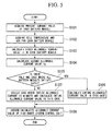
- FIG 5 is a diagram illustrating a process flow of the battery control system.
- each parameter acquiring units 121 of the CMUs 10a to 10c of the BMS 1 acquires the value of charging and discharging current of each battery module 30 from the ammeters 3a to 3c (step S101).
- the value of charging and discharging current of the battery module 30a is referred to as Ia
- the value of charging and discharging current of the battery module 30b is referred to as Ib
- the value of charging and discharging current of the battery module 30c is referred to as Ic.
- the parameter acquiring unit 121 of the CMU 10 outputs the acquired current values Ia to Ic to the BMU 20.
- each parameter acquiring unit 121 of the CMUs 10a to 10c acquires the cell temperature from the thermometer 5 attached to each secondary battery 2 and outputs the value to the BMU 20.
- the BMU 20 calculates the SOC for each secondary battery 2 according to the above-described known method (step S102). Specifically, with regard to the cell temperature of the battery module 30a, for example, the CMU 10a acquires the temperature value from the thermometer 5a attached to the secondary battery 2a, and outputs the acquired temperature value as the cell temperature of the battery module 30a to the BMU 20. Further, with regard to the SOC of the battery module 30a, for example, the BMU 20 calculates the SOC from the accumulated value of the current of the secondary battery 2a of which the temperature value is acquired. Furthermore, the same applies to the secondary battery 2b.
- the CMU 10b acquires the temperature value from the thermometer 5c attached to the secondary battery 2c, and outputs the acquired temperature value as the cell temperature of the battery module 30b to the BMU 20.
- the BMU 20 calculates the SOC from the accumulated value of the current of the secondary battery 2c of which the temperature value is acquired. Furthermore, the same applies to the secondary battery 2d.
- the CMU 10c acquires the temperature value from the thermometer 5e attached to the secondary battery 2e, and outputs the acquired temperature value as the cell temperature of the battery module 30c to the BMU 20. Then, with regard to the SOC of the battery module 30c, for example, the BMU 20 calculates the SOC from the accumulated value of the current of the secondary battery 2e of which the temperature value is acquired. Furthermore, the same applies to the secondary battery 2f.
- the cell temperature and the SOC are different for each secondary battery 2.
- the cell temperatures and the SOCs for the respective secondary batteries 2 disposed inside any battery module 30 are substantially the same, and an example which calculates the cell temperature and the SOC for any one secondary battery 2 inside the battery module 30 will be described. Furthermore, an example which calculates the cell temperature and the SOC inside the battery module 30 using another method will be described later.
- a first allowable current value calculating unit 211 of the BMU 20 calculates the first allowable current value of each battery module 30 on the basis of the allowable current value reference table 6 shown in FIG 4 (where the first allowable current values of the battery modules 30a to 30c are respectively defined as Ita, Itb, and Itc) (step S103).
- the respective first allowable current values which are calculated for the respective battery modules indicate the upper limit values of the current which may be charged to or discharged from the respective corresponding battery modules. For example, the upper limit values are set within the range where the respective battery modules may normally be operated.
- the first allowable current value of the battery module 30a is calculated as 15 A or the like on the basis of the allowable current value reference table 6.
- a second allowable current value calculating unit 221 of the BMU 20 calculates a current value of each of the other battery modules 30 when a current of the first allowable current value is charged to or discharged from the reference battery modules 30a to 30c (the current value is set as the second allowable current value) (step S104). Then, with regard to the second allowable current value, for example, the second allowable current values of the battery modules 30b and 30c are respectively defined as Ipab and Ipac when the battery module 30a is set as a reference.
- the second allowable current values of the battery modules 30a and 30c are respectively defined as Ipba and Ipbc when the battery module 30b is set as a reference. Then, the second allowable current values of the battery modules 30a and 30b are respectively defined as Ipca and Ipcb when the battery module 30c is set as a reference.
- each first allowable current value of each battery module 30 is calculated from the allowable current value reference table 6.
- this value is not obtained in consideration of uneven impedance between the respective battery modules 30. That is, each battery module 30 has original impedance due to differences in the wiring length or the contact resistance between the battery management unit and each battery module 30, and this impedance is not the same in general. However, this is not taken into consideration.
- step S104 the allowable current value is calculated again on the basis of the first allowable current value of each battery module 30 so that no battery module 30 exceeds the allowable current value.
- the second allowable current values Ipab and Ipac have the following values.
- Ipab Ib ⁇ Ita / Ia
- Ipac Ic ⁇ Ita / Ia
- the second allowable current values when the battery module 30b is set as a reference and the battery module 30c is set as a reference are respectively as below.
- Ipba Ia ⁇ Itb / Ib
- Ipbc Ic ⁇ Itb / Ib
- Ipbb Itb
- Ipca Ia ⁇ Itc / Ic
- Ipcb Ib ⁇ Itc / Ic
- Ipcb Itc
- a determining unit 231 of the BMU 20 determines whether the calculated second allowable current value of each of the other battery modules 30 based on a certain reference battery module 30 exceeds the first allowable current value of the battery module 30 calculated in step S103 for every battery module 30, and determines whether one of combinations of the second allowable current values of the respective battery modules or a plurality of combinations satisfies this determination (step S105). Specifically, for example, when the battery module 30a is set as a reference, the BMU 20 determines whether the following relationship is satisfied. Ipab ⁇ Itb and Ipac ⁇ Itc
- this relationship is used to determine whether each of the battery module 30b and the battery module 30c exceeds the first allowable current value when a current corresponding to a current increase rate of the battery module 30a is charged to or discharged from the other battery modules 30b and 30c.
- the combination of the second allowable current value (which is referred to as Case 1) includes Ita, Ipab, and Ipac in order of the battery module 30a, the battery module 30b, and the battery module 30c. Since the first allowable current value of the battery module 30a is set as a reference, the second allowable current value of the battery module 30a is equal to the first allowable current value.
- the determination equation when the first allowable current value of the battery module 30b is set as a reference is expressed as below.
- the combination (which is referred to as Case 2) includes Ipba, Itb, and Ipbc in order of the battery module 30a, the battery module 30b, and the battery module 30c.
- the determination equation when the first allowable current value of the battery module 30c is set as a reference is expressed as below.
- the combination (which is referred to as Case 3) includes Ipca, Ipcb, and Itc in order of the battery module 30a, the battery module 30b, and the battery module 30c. Furthermore, in step S105, a determination is performed on the assumption that one or more pairs of combinations satisfying the above-described relationship are essentially present in Case 1 to Case 3. However, the assumption that one or more pairs of combinations satisfying the above-described relationship are essentially present may be proved mathematically. Accordingly, the determining unit 231 of the BMU 20 determines that at least one combination satisfies the above-described relationship.
- a calculating unit 241 of the BMU 20 calculates the allowable current value (Imax) of the current which is output from the entire battery unit of the combination, that is, the battery pack (step S106). Specifically, the allowable current value (Imax) is obtained by summing the respective second allowable current values of the combination satisfying the above-described relationship. For example, when the combination based on the first allowable current value of the battery module 30a satisfies the above-described relationship in step S105, the allowable current value Imax of the entire battery unit is expressed by the following equation.
- Imax Ita + Ib ⁇ Ita / Ia + Ic ⁇ Ita / Ia
- the allowable current value Imax of the entire battery unit is expressed by the following equation.
- Imax Ia ⁇ Itb / Ib + Itb + Ic ⁇ Itb / Ib
- the allowable current value Imax of the entire battery unit is expressed by the following equation.
- Imax Ia ⁇ Itc / Ic + Ib ⁇ Itc / Ic + Itc
- an allowable current value notifying unit 251 of the BMU 20 notifies the allowable current value Imax in the above-described combination as the allowable current value Imax of the entire battery unit to the high-order system control unit 200 (step S108).
- the determining unit 231 of the BMU 20 allows the calculating unit 241 to calculate the allowable current value (Imax) for each combination, and selects the combination in which the value is the largest. Subsequently, the calculating unit 241 outputs the allowable current value Imax of the combination selected by the determining unit 231 to the allowable current value notifying unit (step S 107).
- the BMU 20 compares the respective values Imax, and notifies the larger value as the allowable current value Imax of the entire battery unit to the high-order system control unit 200.
- the compared values Imax are equal to each other, the value is notified as the allowable current value Imax of the entire battery unit to the outside (in the embodiment, the high-order system control unit 200 of the electric vehicle).
- two values Imax of the battery module 30b and the battery module 30c are compared with each other, but the number may be three or more depending on the number of the battery modules 30 which are connected in parallel to each other. Even in this case, the determining unit 231 of the BMU 20 determines that the larger value is the allowable current value Imax of the entire battery unit.
- an allowable current value notifying unit 251 of the BMU 20 notifies the allowable current value Imax calculated in step S106 or step S107 to the high-order system control unit 200 (step S108). Furthermore, the BMU 20 repeats the process from step S101 to step S108 every predetermined period.
- the predetermined period may be, for example, every second or every few minutes. Further, the interval of the above-described predetermined period may be shortened as the change rate of the current required in the power load 9 becomes larger.
- the high-order system control unit 200 When the high-order system control unit 200 which is mounted on the vehicle receives the allowable current value from the BMU 20, the high-order system control unit limits the current value which is required to the battery unit 50 by the power load 9 by setting the allowable current value as the upper limit. Furthermore, the high-order system control unit 200 displays a message which sends a reminder to driver by controlling the display unit 300. As the message, a variety of content may be applied. However, for example, the fact that the present current supplied as power is close to the above-described allowable current value and the acceleration desired by the driver may not be obtained may be displayed or the fact that the remainder of the above-described allowable current value (for example, the remainder of 20% or the like) may be displayed.
- a current which exceeds the allowable current is prevented from charging to or discharging from the plural battery modules constituting the battery unit. Accordingly, it is possible to prevent the output of the battery unit from being degraded or prevent from the degradation of the secondary battery constituting the battery module.
- the cell temperature and the SOC are substantially the same with the battery module 30.
- the cell temperature and the SOC of the battery module 30 may be calculated by comparing the respective cell temperatures and the respective SOCs of the plural secondary batteries 2 constituting a certain battery module 30 with each other.
- the modified example will be described.
- the battery module 30a has a configuration in which two secondary batteries 2a and 2b are connected in series to each other. Therefore, in step S102, the BMU 20 acquires the cell temperatures Ta and Tb from the respective secondary batteries 2a and 2b, and calculates SOCa and SOCb of the respective secondary batteries 2a and 2b by the above-described method.
- the CMU 10a acquires the cell temperature from the thermometer 5a. With regard to the cell temperature of the secondary battery 2b, the CMU 10a acquires the cell temperature from the thermometer 5b. Then, the acquired temperature values are output to the BMU 20. Further, the CMU 10b and the CMU 10c also perform the same process as that of the CMU 10a, and respectively acquire the cell temperatures of the secondary batteries 2. Then, this temperature values are output to the BMU 20.
- step S103 with regard to the battery module 30a, the BMU 20 acquires the allowable current value of each of the secondary batteries 2a and 2b from the allowable current value table 6. Then, the BMU 20 determines the smaller value of two acquired allowable current values as the first allowable current value in the battery module 30a. If the larger value is set as the first allowable current value, a current which exceeds the allowable current value flows to one of the secondary batteries 2a and 2b constituting the battery module 30a.
- the BMU 20 detects the cell temperature of each of the secondary batteries 2c to 2f and calculates the SOC thereof, and determines the first allowable current value for each battery module 30.
- the first allowable current value is determined in a manner such that the cell temperature and the SOC for each secondary battery 2 constituting the battery module 30 are calculated and the allowable current values of the respective secondary batteries 2 are compared with each other.
- the first allowable current value which is obtained for each battery module does not exceed the allowable current values of either secondary batteries constituting the battery module, and the first allowable current value for each battery module 30 may be calculated with higher accuracy.
- the high-order system control unit 200 which receives the allowable current value from the BMU 20 limits the current required by the power load 9 by the allowable current value, but the invention is not limited thereto.
- the battery control system is not an electric vehicle, but a hybrid vehicle on which an engine is also mounted, a control may be performed so that the difference between the current required by the power load 9 and the allowable current value, that is, the insufficient current amount is substantially compensated for by the power from the engine.
- the modified example 2 will be described.
- the high-order system control unit 200 When the high-order system control unit 200 which is mounted on the hybrid vehicle receives the allowable current value from the BMU 20, the high-order system control unit stores the allowable current value in storage means such as a memory (not shown). On the other hand, the high-order system control unit 200 monitors the value of the current which is required by the power load 9, and frequently monitors whether the required current exceeds the allowable current value Imax transmitted from the BMU 20.
- the high-order system control unit 200 calculates the necessary power of the engine with respect to the difference. Subsequently, the high-order system control unit 200 drives the engine by generating a control signal so that power corresponding to the insufficient current (the above-described difference) is obtained from the engine on the basis of the necessary power with respect to the above-described calculated difference.
- the insufficient power of the hybrid vehicle based on the allowable current value Imax transmitted from the BMU 20 may be compensated for by the engine. Further, the output of the battery unit may be prevented from being degraded or the lifespan of the secondary battery constituting the battery module may be prevented from being degraded.
- the battery control system has a configuration shown in FIG 1 , and the values of the current which is discharged from the battery modules 30a to 30c at a certain time point are respectively set as 12 A, 8 A, and 4 A.
- the BMU 20 acquires the first allowable current value on the basis of the allowable current value reference table 6 from the values of the cell temperature and the SOC of each battery module 30 through the CMU 10.
- the cell temperatures and the SOCs of the secondary batteries 2 constituting the battery module 30 may be set to be substantially the same, and the first allowable current value may be determined by obtaining the cell temperature and the SOC for each secondary battery 2.
- the first allowable current values of the battery modules 30a to 30c are respectively set as 15 A, 14 A, and 16 A.
- the BMU 20 calculates the current values (the second allowable current values) of the other battery modules 30 when the first allowable current is charged to or discharged from the one battery module 30 corresponding to a reference.
- the second allowable current values in the cases where the respective battery modules 30 are respectively set as a reference are as shown below.
- the BMU 20 determines whether there is one or more cases where each second allowable current value of all battery modules 30 does not exceed the corresponding first allowable current value, on the basis of the first allowable current value and the second allowable current value calculated as described above for every case.
- the second allowable current value of the battery module 30a exceeds the corresponding first allowable current value.
- the respective second allowable current values of the battery module 30a and the battery module 30b exceed the corresponding first allowable current values, it is determined that only Case 1 corresponds to the allowable combination.
- the high-order system control unit 200 which receives the allowable current value Imax from the BMU 20 performs a control in which the current required in the power load 9 is limited by setting the allowable current value Imax (30 A) as the upper limit. That is, when the current value which exceeds the allowable current value Imax is required by the power load 9, the high-order system control unit 200 operates the power load 9 at the allowable current value Imax.
- the CMU 10 or the BMU 20 in the above-described battery control system 100 includes a computer system therein. Then, the above-described process procedure may be stored in a storage medium which is readable as a program format, and when the program is read and run by the computer, the above-described process is performed. Further, the CMU 10 may have a part of the process function of the BMU 20 (for example, a function of measuring the current value), and the BMU 20 may have a part of the process function of the CMU 10.
Landscapes
- Engineering & Computer Science (AREA)
- Power Engineering (AREA)
- Life Sciences & Earth Sciences (AREA)
- Sustainable Development (AREA)
- Sustainable Energy (AREA)
- Transportation (AREA)
- Mechanical Engineering (AREA)
- Chemical & Material Sciences (AREA)
- Manufacturing & Machinery (AREA)
- Chemical Kinetics & Catalysis (AREA)
- Electrochemistry (AREA)
- General Chemical & Material Sciences (AREA)
- Secondary Cells (AREA)
- Electric Propulsion And Braking For Vehicles (AREA)
- Hybrid Electric Vehicles (AREA)
- Charge And Discharge Circuits For Batteries Or The Like (AREA)
- Battery Mounting, Suspending (AREA)
Applications Claiming Priority (2)
| Application Number | Priority Date | Filing Date | Title |
|---|---|---|---|
| JP2010072196A JP5517692B2 (ja) | 2010-03-26 | 2010-03-26 | 電池パックおよび電池制御システム |
| PCT/JP2011/057189 WO2011118711A1 (fr) | 2010-03-26 | 2011-03-24 | Bloc-batterie et système de contrôle de batterie |
Publications (2)
| Publication Number | Publication Date |
|---|---|
| EP2555371A1 true EP2555371A1 (fr) | 2013-02-06 |
| EP2555371A4 EP2555371A4 (fr) | 2015-10-07 |
Family
ID=44673257
Family Applications (1)
| Application Number | Title | Priority Date | Filing Date |
|---|---|---|---|
| EP11759516.5A Withdrawn EP2555371A4 (fr) | 2010-03-26 | 2011-03-24 | Bloc-batterie et système de contrôle de batterie |
Country Status (6)
| Country | Link |
|---|---|
| US (1) | US8958934B2 (fr) |
| EP (1) | EP2555371A4 (fr) |
| JP (1) | JP5517692B2 (fr) |
| KR (1) | KR101323511B1 (fr) |
| CN (1) | CN102474118B (fr) |
| WO (1) | WO2011118711A1 (fr) |
Families Citing this family (37)
| Publication number | Priority date | Publication date | Assignee | Title |
|---|---|---|---|---|
| CN103076768B (zh) * | 2011-10-25 | 2015-04-22 | 比亚迪股份有限公司 | 分布式电池管理系统及其标识分配方法 |
| US9197096B2 (en) * | 2012-01-19 | 2015-11-24 | Apple Inc. | Charging techniques for solid-state batteries in portable electronic devices |
| JP5461602B2 (ja) | 2012-02-20 | 2014-04-02 | 三菱重工業株式会社 | 電力管理システム |
| JP2013207901A (ja) | 2012-03-28 | 2013-10-07 | Sanyo Electric Co Ltd | 電池制御装置 |
| JP2014011917A (ja) * | 2012-07-02 | 2014-01-20 | Mitsubishi Heavy Ind Ltd | 充電率均等化装置及び電池システム |
| JPWO2014024452A1 (ja) * | 2012-08-09 | 2016-07-25 | 三洋電機株式会社 | バッテリシステム及びこのバッテリシステムを備える電動車両並びに蓄電装置 |
| TW201507319A (zh) * | 2013-08-05 | 2015-02-16 | Hon Hai Prec Ind Co Ltd | 充放電系統 |
| JP6168962B2 (ja) * | 2013-10-10 | 2017-07-26 | 三菱重工業株式会社 | 異常判定装置、充放電情報提示装置、二次電池モジュール、異常判定方法、及びプログラム |
| JP2015104225A (ja) * | 2013-11-25 | 2015-06-04 | ソニー株式会社 | 蓄電システムおよび二次電池の充電方法 |
| JP6241379B2 (ja) * | 2014-07-03 | 2017-12-06 | トヨタ自動車株式会社 | 電動車両 |
| JP6316690B2 (ja) * | 2014-07-17 | 2018-04-25 | 日立オートモティブシステムズ株式会社 | 電池状態検知装置、二次電池システム、電池状態検知プログラム、電池状態検知方法 |
| JP6361545B2 (ja) * | 2015-03-24 | 2018-07-25 | 株式会社豊田自動織機 | 電流制御装置 |
| JP2016220450A (ja) * | 2015-05-22 | 2016-12-22 | 三菱重工業株式会社 | 電源制御装置、電源システム、電源制御方法およびプログラム |
| EP3352288B1 (fr) * | 2015-09-16 | 2020-02-26 | Kabushiki Kaisha Toshiba | Module de batterie et bloc-batterie |
| GB201523105D0 (en) * | 2015-12-30 | 2016-02-10 | Hyperdrive Innovation Ltd | Battery management system |
| JP6409203B2 (ja) * | 2016-03-25 | 2018-10-24 | 本田技研工業株式会社 | 電源装置、輸送機器、電源制御方法、および制御装置 |
| EP3518382B1 (fr) * | 2016-09-21 | 2022-03-30 | Envision AESC Japan Ltd. | Système d'alimentation électrique |
| KR101704359B1 (ko) * | 2016-10-10 | 2017-02-22 | 송성훈 | 배터리 충전관리장치 |
| DE102017102257A1 (de) * | 2017-02-06 | 2018-08-09 | Man Diesel & Turbo Se | Schiffs- oder Kraftwerksspannungsversorgungssystem |
| US12409756B2 (en) | 2017-04-05 | 2025-09-09 | H55 Sa | Aircraft monitoring system and method for electric or hybrid aircrafts |
| US11063323B2 (en) | 2019-01-23 | 2021-07-13 | H55 Sa | Battery module for electrically-driven aircraft |
| US11148819B2 (en) | 2019-01-23 | 2021-10-19 | H55 Sa | Battery module for electrically-driven aircraft |
| US10479223B2 (en) * | 2018-01-25 | 2019-11-19 | H55 Sa | Construction and operation of electric or hybrid aircraft |
| US11065979B1 (en) | 2017-04-05 | 2021-07-20 | H55 Sa | Aircraft monitoring system and method for electric or hybrid aircrafts |
| CN107364363A (zh) * | 2017-08-15 | 2017-11-21 | 安徽华凯新能源科技有限公司 | 电动叉车动力电池组用新型充电机 |
| WO2019039114A1 (fr) * | 2017-08-23 | 2019-02-28 | ソニー株式会社 | Dispositif de commande de stockage d'électricité, procédé de commande de stockage d'électricité, et système de stockage d'électricité |
| JP6870589B2 (ja) * | 2017-11-20 | 2021-05-12 | トヨタ自動車株式会社 | 電源装置 |
| KR102530221B1 (ko) | 2017-11-28 | 2023-05-09 | 삼성전자주식회사 | 배터리 관리 방법 및 장치 |
| DE102018105505A1 (de) | 2018-03-09 | 2019-09-12 | Man Truck & Bus Ag | Verfahren zur Erkennung einer Fehlfunktion, insbesondere eines Kurzschlussstroms, in einer Traktionsbatterieanordnung |
| EP3898313A1 (fr) | 2018-12-20 | 2021-10-27 | Volvo Truck Corporation | Procédé amélioré de commande d'un système de stockage d'énergie |
| KR102003360B1 (ko) * | 2019-03-11 | 2019-07-24 | (주)시그넷이브이 | 전기차 충전 시스템의 전기차 충전 방법 |
| US10843578B2 (en) * | 2019-03-22 | 2020-11-24 | Caterpillar Inc. | Configuration for battery powered electric drive load haul dump |
| KR102680305B1 (ko) * | 2019-10-30 | 2024-06-28 | 주식회사 엘지에너지솔루션 | 병렬 멀티 팩 시스템의 출력 제어 장치 및 방법 |
| WO2022019664A1 (fr) * | 2020-07-21 | 2022-01-27 | 주식회사 엘지에너지솔루션 | Dispositif et procédé de commande de sortie de module multi-bloc parallèle |
| JP7323506B2 (ja) * | 2020-12-25 | 2023-08-08 | プライムプラネットエナジー&ソリューションズ株式会社 | 蓄電システム、および蓄電システムの制御装置 |
| JP2022125890A (ja) * | 2021-02-17 | 2022-08-29 | トヨタ自動車株式会社 | 飛行体 |
| FR3129881A1 (fr) * | 2021-12-03 | 2023-06-09 | Psa Automobiles Sa | Surveillance du courant fourni par une batterie principale d’un véhicule |
Family Cites Families (29)
| Publication number | Priority date | Publication date | Assignee | Title |
|---|---|---|---|---|
| JPH08123587A (ja) * | 1994-10-27 | 1996-05-17 | Canon Inc | 携帯型情報処理装置 |
| JP2001185228A (ja) | 1999-12-24 | 2001-07-06 | Sanyo Electric Co Ltd | 電池を備える電源装置 |
| US6700766B2 (en) * | 2000-09-14 | 2004-03-02 | Sony Corporation | Overvoltage protection circuit with thermal fuse, zener diode, and posistor |
| US7564220B2 (en) * | 2000-09-21 | 2009-07-21 | O2Micro International Ltd. | Method and electronic circuit for efficient battery wake up charging |
| JP4047558B2 (ja) * | 2001-05-29 | 2008-02-13 | 松下電器産業株式会社 | 電池電圧検出装置 |
| JP3994700B2 (ja) | 2001-08-09 | 2007-10-24 | 日産自動車株式会社 | 組電池、組電池構造体、組電池又は組電池構造体を備えた車両、及び組電池又は組電池構造体の制御方法 |
| JP3638263B2 (ja) * | 2001-09-10 | 2005-04-13 | 本田技研工業株式会社 | 車両駆動装置 |
| JP2004007950A (ja) * | 2002-04-15 | 2004-01-08 | Fuji Electric Holdings Co Ltd | スイッチング電源装置 |
| JP2005094914A (ja) * | 2003-09-17 | 2005-04-07 | Nissan Motor Co Ltd | 燃料電池車両の電力供給システム |
| US7321220B2 (en) * | 2003-11-20 | 2008-01-22 | Lg Chem, Ltd. | Method for calculating power capability of battery packs using advanced cell model predictive techniques |
| JP2005297860A (ja) * | 2004-04-14 | 2005-10-27 | Toyota Motor Corp | 車両用電源装置 |
| US20060103348A1 (en) * | 2004-11-15 | 2006-05-18 | Melichar Robert J | Maximum and minimum power limit calculator for parallel battery subpacks |
| KR100740106B1 (ko) * | 2005-09-12 | 2007-07-16 | 삼성에스디아이 주식회사 | 배터리 관리 시스템 및 그의 구동 방법 |
| JP5089883B2 (ja) * | 2005-12-16 | 2012-12-05 | 日立ビークルエナジー株式会社 | 蓄電池管理装置 |
| JP4821363B2 (ja) * | 2006-02-21 | 2011-11-24 | 日産自動車株式会社 | 組電池制御装置および組電池制御方法 |
| JP4773848B2 (ja) * | 2006-03-03 | 2011-09-14 | プライムアースEvエナジー株式会社 | 二次電池の充放電制御システム、電池制御装置、およびプログラム |
| JP5314235B2 (ja) * | 2006-03-07 | 2013-10-16 | プライムアースEvエナジー株式会社 | 二次電池の温度制御装置、二次電池の加温システム、およびプログラム |
| US8466684B2 (en) * | 2006-06-16 | 2013-06-18 | Chevron Technology Ventures Llc | Determination of battery predictive power limits |
| DE102008000704A1 (de) * | 2007-04-24 | 2008-10-30 | Robert Bosch Gmbh | Elektrowerkzeug und Geräteschalter für ein Elektrowerkzeug |
| JP4987581B2 (ja) * | 2007-06-15 | 2012-07-25 | 日立ビークルエナジー株式会社 | 電池制御装置 |
| EP2302724A4 (fr) * | 2008-07-17 | 2013-12-11 | Mitsubishi Heavy Ind Ltd | Système de batterie de stockage, dispositif de surveillance de batterie de stockage, et procédé de surveillance de batterie de stockage |
| JP5131110B2 (ja) | 2008-09-17 | 2013-01-30 | コニカミノルタビジネステクノロジーズ株式会社 | 固定構造、光走査装置、画像形成装置及び固定方法 |
| JP5386155B2 (ja) * | 2008-11-28 | 2014-01-15 | 株式会社日立製作所 | 蓄電装置 |
| JP4796119B2 (ja) * | 2008-12-09 | 2011-10-19 | 三菱重工業株式会社 | 電池装置 |
| JP5331493B2 (ja) * | 2009-01-13 | 2013-10-30 | 日立ビークルエナジー株式会社 | 電池制御装置 |
| WO2010109956A1 (fr) * | 2009-03-27 | 2010-09-30 | 株式会社日立製作所 | Dispositif de stockage électrique |
| JP2010271288A (ja) | 2009-05-25 | 2010-12-02 | Mitsubishi Heavy Ind Ltd | 電池充電率演算装置、電池充電率演算方法、及びプログラム |
| JP2010271287A (ja) | 2009-05-25 | 2010-12-02 | Mitsubishi Heavy Ind Ltd | 電池劣化判定装置、電池劣化判定方法、及びプログラム |
| JP2010271286A (ja) | 2009-05-25 | 2010-12-02 | Mitsubishi Heavy Ind Ltd | 電池劣化判定装置、電池劣化判定方法、及びプログラム |
-
2010
- 2010-03-26 JP JP2010072196A patent/JP5517692B2/ja active Active
-
2011
- 2011-03-24 CN CN201180003222.3A patent/CN102474118B/zh active Active
- 2011-03-24 US US13/394,454 patent/US8958934B2/en active Active
- 2011-03-24 KR KR1020127003307A patent/KR101323511B1/ko active Active
- 2011-03-24 WO PCT/JP2011/057189 patent/WO2011118711A1/fr not_active Ceased
- 2011-03-24 EP EP11759516.5A patent/EP2555371A4/fr not_active Withdrawn
Non-Patent Citations (1)
| Title |
|---|
| See references of WO2011118711A1 * |
Also Published As
| Publication number | Publication date |
|---|---|
| EP2555371A4 (fr) | 2015-10-07 |
| WO2011118711A1 (fr) | 2011-09-29 |
| US20120166031A1 (en) | 2012-06-28 |
| US8958934B2 (en) | 2015-02-17 |
| KR20120049253A (ko) | 2012-05-16 |
| JP5517692B2 (ja) | 2014-06-11 |
| JP2011205827A (ja) | 2011-10-13 |
| KR101323511B1 (ko) | 2013-10-29 |
| CN102474118B (zh) | 2014-10-29 |
| CN102474118A (zh) | 2012-05-23 |
Similar Documents
| Publication | Publication Date | Title |
|---|---|---|
| US8958934B2 (en) | Battery pack and battery control system | |
| EP1918729B1 (fr) | Test de pronostic de batterie au lithium ion et procédé | |
| EP1837944B1 (fr) | Appareil de contrôle d'alimentation électrique | |
| US9680320B2 (en) | Battery control apparatus | |
| EP4169143B1 (fr) | Procédé de prédiction d'état de puissance d'un système de stockage d'énergie électrique à batteries multiples | |
| CN103080762B (zh) | 电池劣化检测装置、电池劣化检测方法及其程序 | |
| US8738311B2 (en) | State-of-charge estimation method and battery control unit | |
| EP2649700B1 (fr) | Équilibrage de tension pour un système de batterie à multiples cellules | |
| JP4472733B2 (ja) | バッテリー管理システム及びその駆動方法 | |
| US8878493B2 (en) | Apparatus for monitoring operation state of battery pack composed of plurality of cells mutually connected in series | |
| KR100814883B1 (ko) | 배터리 관리 시스템 및 그의 구동 방법 | |
| EP2637032A1 (fr) | Système de prédiction d'anomalie de batteries | |
| KR101672314B1 (ko) | 배터리 모니터링 시스템 | |
| KR20020064998A (ko) | 배터리 성능 측정 시스템 및 측정방법 | |
| TW201223069A (en) | Systems and methods for battery management | |
| JPH07503597A (ja) | 充放電中にバッテリを監視するシステム | |
| EP3907813B1 (fr) | Appareil de mesure de température, appareil à batterie le comprenant et procédé de mesure de température | |
| KR20170088530A (ko) | 전기구동장치의 다중화 배터리팩 전원공급시스템 | |
| EP3808592B1 (fr) | Procédé de détermination du support de contenu en énergie et d'alimentation d'une batterie | |
| CN113631938A (zh) | 用于检测并联电池单元的连接故障的方法和系统 | |
| WO2024064344A2 (fr) | Procédés et systèmes de vérification de capacité de batterie pour la détermination de la qualité de l'air | |
| EP4333253A1 (fr) | Procédé de commande de batterie | |
| KR101541741B1 (ko) | 배터리 관리 시스템을 내장하고 있는 충전 케이블 및 이를 이용한 전동차 | |
| KR20190027110A (ko) | 탈부착이 가능한 배터리 상태 연산모듈 및 이를 포함하는 배터리 | |
| JPH11317243A (ja) | 自動車用電池交換時の容量演算方法 |
Legal Events
| Date | Code | Title | Description |
|---|---|---|---|
| PUAI | Public reference made under article 153(3) epc to a published international application that has entered the european phase |
Free format text: ORIGINAL CODE: 0009012 |
|
| 17P | Request for examination filed |
Effective date: 20120307 |
|
| AK | Designated contracting states |
Kind code of ref document: A1 Designated state(s): AL AT BE BG CH CY CZ DE DK EE ES FI FR GB GR HR HU IE IS IT LI LT LU LV MC MK MT NL NO PL PT RO RS SE SI SK SM TR |
|
| DAX | Request for extension of the european patent (deleted) | ||
| RA4 | Supplementary search report drawn up and despatched (corrected) |
Effective date: 20150908 |
|
| RIC1 | Information provided on ipc code assigned before grant |
Ipc: B60L 11/18 20060101ALI20150902BHEP Ipc: G01R 31/36 20060101ALI20150902BHEP Ipc: H02J 7/00 20060101AFI20150902BHEP |
|
| 17Q | First examination report despatched |
Effective date: 20180530 |
|
| STAA | Information on the status of an ep patent application or granted ep patent |
Free format text: STATUS: THE APPLICATION IS DEEMED TO BE WITHDRAWN |
|
| 18D | Application deemed to be withdrawn |
Effective date: 20190817 |