EP2555414A2 - Motorsteuereinheit und elektrisches Servolenkungssystem - Google Patents
Motorsteuereinheit und elektrisches Servolenkungssystem Download PDFInfo
- Publication number
- EP2555414A2 EP2555414A2 EP12177027A EP12177027A EP2555414A2 EP 2555414 A2 EP2555414 A2 EP 2555414A2 EP 12177027 A EP12177027 A EP 12177027A EP 12177027 A EP12177027 A EP 12177027A EP 2555414 A2 EP2555414 A2 EP 2555414A2
- Authority
- EP
- European Patent Office
- Prior art keywords
- voltage
- value
- motor
- zero
- detected
- Prior art date
- Legal status (The legal status is an assumption and is not a legal conclusion. Google has not performed a legal analysis and makes no representation as to the accuracy of the status listed.)
- Granted
Links
Images



Classifications
-
- H—ELECTRICITY
- H02—GENERATION; CONVERSION OR DISTRIBUTION OF ELECTRIC POWER
- H02P—CONTROL OR REGULATION OF ELECTRIC MOTORS, ELECTRIC GENERATORS OR DYNAMO-ELECTRIC CONVERTERS; CONTROLLING TRANSFORMERS, REACTORS OR CHOKE COILS
- H02P6/00—Arrangements for controlling synchronous motors or other dynamo-electric motors using electronic commutation dependent on the rotor position; Electronic commutators therefor
-
- H—ELECTRICITY
- H02—GENERATION; CONVERSION OR DISTRIBUTION OF ELECTRIC POWER
- H02P—CONTROL OR REGULATION OF ELECTRIC MOTORS, ELECTRIC GENERATORS OR DYNAMO-ELECTRIC CONVERTERS; CONTROLLING TRANSFORMERS, REACTORS OR CHOKE COILS
- H02P7/00—Arrangements for regulating or controlling the speed or torque of electric DC motors
-
- H—ELECTRICITY
- H02—GENERATION; CONVERSION OR DISTRIBUTION OF ELECTRIC POWER
- H02P—CONTROL OR REGULATION OF ELECTRIC MOTORS, ELECTRIC GENERATORS OR DYNAMO-ELECTRIC CONVERTERS; CONTROLLING TRANSFORMERS, REACTORS OR CHOKE COILS
- H02P6/00—Arrangements for controlling synchronous motors or other dynamo-electric motors using electronic commutation dependent on the rotor position; Electronic commutators therefor
- H02P6/14—Electronic commutators
Definitions
- the invention relates to a motor control unit that controls a brushed motor, and an electric power steering system that includes the motor control unit.
- JP 2010-029029 A describes a method of estimating a rotational speed of a motor in an electric power steering system. In the method, an induced voltage generated with the rotation of a rotor that constitutes the motor is estimated, and a rotational speed of the motor is calculated on the basis of the estimated induced voltage.
- JP 2010-029029 A describes a motor control unit that calculates an induced voltage generated at the brushless motor.
- the motor control unit includes a disturbance observer (induced voltage calculation means) that calculates an induced voltage as a disturbance.
- a disturbance observer induced voltage calculation means
- the first method is to detect an inter-terminal voltage of a motor (hereinafter, also referred to as “detected voltage value”) as a detected voltage value with the use of a known sensor (voltmeter).
- the second method is to calculate an estimated value of an inter-terminal voltage of a motor (hereinafter, also referred to as “estimated voltage value”) by multiplying a voltage of a battery that serves as a power supply source for the motor (i.e., battery voltage) by a duty ratio of a drive signal input into the motor.
- the estimated voltage value is higher in resolution than the detected voltage value. Therefore, the accuracy of an induced voltage calculated with the use of the estimated voltage value is higher than the accuracy of an induced voltage calculated with the use of the detected voltage value.
- an induced voltage generated at a brushed motor is calculated, the following inconvenience occurs if an estimated voltage value is used. That is, when a target current value for the brushed motor is zero, a duty ratio of a drive signal input into the motor is set to zero. Therefore, it is not possible to calculate an estimated voltage value. Accordingly, when an induced voltage generated at the brushed motor is calculated, a detected voltage value is generally used. In this case, although it is possible to calculate an induced voltage irrespective of the magnitude of a target current value, the accuracy of a calculated induced voltage is lower than that when an estimated voltage value is used.
- the invention provides a motor control unit and an electric power steering system that are able to calculate an induced voltage generated at a brushed motor irrespective of the magnitude of a target current value for the motor and that are able to improve the accuracy of calculation of the induced voltage.
- a motor control unit when a target value of current that is passed through a motor is zero, an induced voltage generated at the motor is calculated with the use of a voltage value based on a detected voltage value; whereas, when the target value of current is not zero, the induced voltage generated at the motor is calculated with the use of a voltage value based on an estimated voltage value that is higher in resolution than the detected voltage value.
- a voltage value that is input into induced voltage calculation means is adjusted so as to be brought from the detected voltage value detected before the target value of current is changed, closer to the estimated voltage value calculated after the target value of current is changed.
- the voltage value that is input into the induced voltage calculation means is adjusted so as to be brought from the estimated voltage value calculated before the target value of current is changed, closer to the detected voltage value detected after the target value of current is changed.
- the voltage value that is input into the induced voltage calculation means is gradually brought from the detected voltage value detected before the target value of current is changed, closer to the estimated voltage value calculated after the target value of current is changed, and becomes the estimated voltage value after a lapse of an adjustment time from the time when the target value of current is changed.
- the voltage value that is input into the induced voltage calculation means is gradually brought from the estimated voltage value calculated before the target value of current is changed, closer to the detected voltage value detected after the target value of current is changed, and becomes the detected voltage value after a lapse of the adjustment time from the time when the target value of current is changed.
- an electric power steering system 1 includes a steering shaft 3 to which a steering wheel 2 is fixed.
- the steering shaft 3 is coupled to a rack shaft 5 via a rack-and-pinion mechanism 4.
- the rotation of the steering shaft 3 resulting from an operation of the steering wheel 2 is converted into a reciprocal linear motion of the rack shaft 5 by the rack-and-pinion mechanism 4.
- the steering shaft 3 according to the present embodiment is formed by coupling a column shaft 3a, an intermediate shaft 3b and a pinion shaft 3c to each other.
- the reciprocal linear motion of the rack shaft 5 resulting from the rotation of the steering shaft 3 is transmitted to knuckles (not shown) via tie rods 6 coupled to respective ends of the rack shaft 5.
- the steered angle of steered wheels 7 is changed.
- the electric power steering system 1 includes an actuator 10 and an ECU 11.
- the actuator 10 applies assist force for assisting a steering operation to a steering system.
- the ECU 11 that may function as a motor control unit and that controls the operation of the actuator 10.
- the actuator 10 is a so-called column-type actuator in which a brushed motor 12 is drivably coupled to the column shaft 3a via a speed reduction mechanism 13.
- the thus configured actuator 10 reduces the speed of rotation of the motor 12 using the speed reduction mechanism 13 and then transmits the rotation with the reduced speed to the column shaft 3a, thereby applying assist force based on the motor torque to the steering system.
- a torque sensor 14, a vehicle speed sensor 15 and a steering sensor 16 are electrically connected to the ECU 11.
- the torque sensor 14 detects a steering torque ⁇ transmitted to the steering shaft 3.
- the vehicle speed sensor 15 detects a vehicle speed Vs.
- the steering sensor 16 detects a steering angle ⁇ s of the steering wheel 2.
- the ECU 11 computes a target assist force that is applied to the steering system on the basis of the above information, and outputs a drive signal SD to the motor 12 such that the motor 12 generates a motor torque corresponding to the target assist force. In this way, the ECU 11 controls assist force that is applied to the steering system.
- the ECU 11 includes a microcomputer 20 and a drive circuit 21.
- the microcomputer 20 is formed of, for example, a CPU, a ROM, a RAM, and a nonvolatile memory (not shown).
- the drive circuit 21 is used to drive the motor 12.
- the vehicle speed sensor 15 and the steering sensor 16 a current sensor 22 and a voltage sensor 23 are electrically connected to the microcomputer 20.
- the current sensor 22 is used to detect a current flowing through the motor 12.
- the voltage sensor 23 is used to detect an inter-terminal voltage of the motor 12.
- the drive circuit 21 has various electronic components (not shown), such as switching elements (for example, FETs).
- a power supply voltage Vps is applied from a battery 24 that is a power supply source of a vehicle to the drive circuit 21.
- the drive circuit 21 generates a drive signal SD having a duty ratio based on a control command from the microcomputer 20, and outputs the drive signal SD to the motor 12.
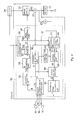
- the microcomputer 20 includes a target current value setting unit 30, a current detecting unit 31, a deviation calculation unit 32, a PI control unit 33, a power supply voltage acquisition unit 34, a duty ratio setting unit 35, a PWM control unit 36, an input voltage setting unit 37, an induced voltage observer 38, and a rotational speed calculation unit 39.
- These functional units 30 to 39 may be formed of either hardware or software.
- the target current value setting unit 30 sets a target current value It that is a target value of current that is passed through the motor 12 on the basis of a steering torque ⁇ detected by the torque sensor 14 and a vehicle speed Vs detected by the vehicle speed sensor 15. For example, the target current value It is set to a larger value as the steering torque ⁇ increases, and is set to a larger value as the vehicle speed Vs decreases. Then, the target current value setting unit 30 outputs the set target current value It to the deviation calculation unit 32 and the input voltage setting unit 37. Therefore, in the present embodiment, the target current value setting unit 30 may function as target value setting means.
- the current detecting unit 31 detects a detected current value Ie that is a current flowing through the motor 12 on the basis of a detection signal output from the current sensor 22, and then outputs the detected current value Ie to the deviation calculation unit 32 and the induced voltage observer 38.
- the deviation calculation unit 32 calculates a deviation Isub between the received target current value It and detected current value Ie, and then outputs the deviation Isub to the PI control unit 33.
- the PI control unit 33 executes PI operation based on the received deviation Isub to calculate a controlled variable of the motor 12. Then, the PI control unit 33 outputs the controlled variable to the duty ratio setting unit 35.
- the power supply voltage acquisition unit 34 acquires a power supply voltage Vps that is a value of voltage that is allowed to be applied from the battery 24 to the drive circuit 21, and then outputs the power supply voltage Vps to the duty ratio setting unit 35 and the received voltage setting unit 37.
- the duty ratio setting unit 35 sets a duty ratio D of the drive signal SD that is output to the motor 12 on the basis of the received controlled variable and power supply voltage Vps, and then outputs the duty ratio D to the PWM control unit 36 and the input voltage setting unit 37.
- the PWM control unit 36 controls the drive circuit 21 on the basis of the received duty ratio D. Then, the drive circuit 21 generates the drive signal SD corresponding to the received control command, and then outputs the drive signal SD to the motor 12.
- the input voltage setting unit 37 includes a voltage detecting unit 50 that may function as voltage detecting means, a voltage calculation unit 51 that may function as voltage calculation means, a change determination unit 52, and a voltage adjusting unit 53 that may function as voltage adjusting means.
- the voltage detecting unit 50 detects a detected voltage value Vd that is a detected value of an inter-terminal voltage on the basis of a detection signal output from the voltage sensor 23, and then outputs the detected voltage value Vd to the voltage adjusting unit 53.
- the voltage calculation unit 51 calculates an estimated voltage value Ve that is an estimated value of an inter-terminal voltage on the basis of the duty ratio D received from the duty ratio setting unit 35 and the power supply voltage Vps received from the power supply voltage acquisition unit 34. Specifically, the voltage calculation unit 51 multiplies the power supply voltage Vps by the duty ratio D, and then sets the result of multiplication as the estimated voltage value Ve. Then, the voltage calculation unit 51 outputs the estimated voltage value Ve to the voltage adjusting unit 53.
- the target current value It is input into the change determination unit 52 from the target current value setting unit 30. Then, the change determination unit 52 determines whether the target current value It is changed from a value other than zero to zero, and determines whether the target current value It is changed from zero to a value other than zero. Then, the change determination unit 52 outputs the result of determination to the voltage adjusting unit 53. Note that, in the present embodiment, the fact that the target current value It is changed from a value other than zero to zero and the fact that the target current value It is changed from zero to a value other than zero are each expressed as "an affirmative change determination is made".
- the voltage adjusting unit 53 outputs an inter-terminal voltage Vt, based on the information received from the change determination unit 52, to the induced voltage observer 38. That is, the voltage adjusting unit 53 outputs the detected voltage value Vd as the inter-terminal voltage Vt when the target current value It is kept at zero, and outputs the estimated voltage value Ve as the inter-terminal voltage Vt when the target current value It is kept at a value other than zero.
- the situation where "the target current value It is kept at a value other than zero" includes not only the case where the target current value It is kept at a constant value other than zero but also the case where the target current value It is changed form a value other than zero to another value other than zero.
- the voltage adjusting unit 53 adjusts the voltage value such that the voltage value is gradually brought from one of the detected voltage value Vd and the estimated voltage value Ve closer to the other one of these values. Then, the voltage adjusting unit 53 outputs the adjusted voltage value as the inter-terminal voltage Vt.
- FIG. 3 shows a change in the inter-terminal voltage Vt in the case where the target current value It is changed from a value other than zero to zero as an example of a case where an affirmative change determination is made. That is, as shown in FIG. 3 , when the target current value It is changed from a value other than zero to zero, the voltage adjusting unit 53 calculates a difference Vsub between the estimated voltage value Ve calculated before an affirmative change determination is made and the detected voltage value Vd detected at the time when an affirmative change determination is made. In addition, the voltage adjusting unit 53 sets an adjustment time PT such that the larger the calculated difference Vsub is, the longer the adjustment time PT is.
- the voltage adjusting unit 53 adjusts the inter-terminal voltage Vt during the set adjustment time PT such that the inter-terminal voltage Vt is gradually brought from the estimated voltage value Ve calculated before an affirmative change determination is made, closer to the detected voltage value Vd detected after an affirmative change determination is made.
- an amount of change in the inter-terminal voltage Vt per unit time in the case where an affirmative change determination is made is constant irrespective of the magnitude of the difference Vsub.
- the voltage adjusting unit 53 calculates the difference Vsub between the detected voltage value Vd detected before an affirmative change determination is made and the estimated voltage value Ve calculated at the time when an affirmative change determination is made. In addition, the voltage adjusting unit 53 sets the adjustment time PT such that the larger the calculated difference Vsub is, the longer the adjustment time PT is. Then, the voltage adjusting unit 53 adjusts the inter-terminal voltage Vt during the set adjustment time PT such that the inter-terminal voltage Vt is gradually brought from the detected voltage value Vd detected before an affirmative change determination is made, closer to the estimated voltage value Ve calculated after an affirmative change determination is made.
- the induced voltage observer 38 is a disturbance observer that calculates an induced voltage E generated at the motor 12 as a disturbance.
- the thus configured induced voltage observer 38 calculates the induced voltage E generated at the motor 12 on the basis of the inter-terminal voltage Vt received from the input voltage setting unit 37 and the detected current value Ie received from the current detecting unit 31.
- the induced voltage observer 38 may function as induced voltage calculation means. Note that the concrete configuration of the induced voltage observer 38 will be described later.
- the rotational speed calculation unit 39 calculates a rotational speed ⁇ of the motor 12 using the received induced voltage E.
- the rotational speed ⁇ is calculated according to Equation 1 indicated below.
- the rotational speed calculation unit 39 may function as rotational speed calculation means.
- ⁇ E / Ke
- Ke is a reverse voltage constant.
- Equation 2 to 6 the induced voltage observer 38 is expressed by Equations 2 to 6 indicated below.
- a 12 - 1 / L
- B 1 1 / L
- Ts is a computation cycle
- G an observer gain
- ⁇ a variable that indicates an internal state
- n is a number of computation cycle
- R is a resistance value of the motor
- L is an inductance of the motor.
- the rotational speed acquisition process routine is executed at predetermined intervals while an ignition switch (not shown) of the vehicle is kept on.
- step S10 the ECU 11 acquires the target current value It detected at this timing.
- step S11 the ECU 11 determines whether the target current value It acquired in step S10 is zero. When the target current value It is zero ("YES" in step S10), the ECU 11 proceeds to step S12. On the other hand, when the target current value It is not zero ("NO" in step S10), the ECU 11 proceeds to step S20 ( FIG. 6 ), which will be described later.
- step S12 the ECU 11 determines whether a target value flag FLG1 is on.
- the target value flag FLG1 is turned off when the target current value It is zero; whereas the target value flag FLG1 is turned on when the target current value It is a value other than zero.
- the ECU 11 sets the detected voltage value Vd, detected at this timing, as the inter-terminal voltage Vt because the target current value It is kept at zero (step S13). After that, the ECU 11 proceeds to step S28, which will be described later.
- step S12 when the target value flag FLG1 is on ("YES" in step S12), the ECU 11 proceeds to step S14 because the target current value It is changed from a value other than zero to zero. Then, in step S14, the ECU 11 calculates the difference Vsub between the estimated voltage value Ve calculated at the previous timing and the detected voltage value Vd detected at the current timing. Subsequently, in step S15, the ECU 11 sets the adjustment time PT such that the larger the difference Vsub calculated in step S14 is, the longer the adjustment time PT is (see FIG. 3 ).
- step S16 the ECU 11 calculates an adjusted voltage value Va based on an elapsed time T1 from the time when the target current value It is changed from a value other than zero to zero and the adjustment time PT set in step S15.
- the ECU 11 sets the adjusted voltage value Va, calculated in step S16, as the inter-terminal voltage Vt (step S17), and determines whether the elapsed time T1 coincides with the adjustment time PT (step S18). When the elapsed time T1 does not coincide with the adjustment time PT ("NO" in step S18), the ECU 11 proceeds to step S28, which will be described later. On the other hand, when the elapsed time T1 coincides with the adjustment time PT ("YES" in step S18), the ECU 11 turns the target value flag FLG1 off (step S19), and proceeds to step S28, which will be described later.
- step S11 determines in step S20 whether the target value flag FLG1 is on.
- the ECU 11 sets the estimated voltage value Ve, calculated at this timing, as the inter-terminal voltage Vt because the target current value It is kept at a value other than zero (step S21). After that, the ECU 11 proceeds to step S28, which will be described later.
- step S20 when the target value flag FLG1 is off ("NO" in step S20), the ECU 11 proceeds to step S22 because the target current value It is changed from zero to a value other than zero. Then, in step S22, the ECU 11 calculates the difference Vsub between the detected voltage value Vd detected at the previous timing and the estimated voltage value Ve calculated at the current timing. In step S23, the ECU 11 sets the adjustment time PT such that the larger the difference Vsub calculated in step S14 is, the longer the adjustment time PT is.
- step S24 the ECU 11 calculates an adjusted voltage value Va based on an elapsed time T2 from the time when the target current value It is changed from zero to a value other than zero and the adjustment time PT set in step S23.
- the ECU 11 (voltage adjusting unit 53) calculates the adjusted voltage value Va according to Equation 8 indicated below.
- step S25 The ECU 11 sets the adjusted voltage value Va calculated in step S24 as the inter-terminal voltage Vt (step S25), and determines whether the elapsed time T2 coincides with the adjustment time PT (step S26). When the elapsed time T2 is shorter than the adjustment time PT ("NO" in step S26), the ECU 11 proceeds to step S28, which will be described later. On the other hand, when the elapsed time T2 coincides with the adjustment time PT ("YES" in step S26), the ECU 11 turns the target value flag FLG1 on (step S27), and proceeds to step S28.
- step S28 the ECU 11 substitutes the inter-terminal voltage Vt set in one of the steps S13, S17, S21 and S25 and the detected current value Ie detected at this timing into Equations 2 to 6 indicated above to calculate an induced voltage E.
- step S29 the ECU 11 substitutes the induced voltage E calculated in step S28 into Equation 1 indicated above to calculate the rotational speed ⁇ of the motor 12 and, after that, ends the rotational speed acquisition process routine.
- the operation at the time when the induced voltage E generated at the motor 12 is calculated will be described with the emphasis on the operation at the time when an affirmative change determination is made.
- the target current value It is a value other than zero
- the estimated voltage value Ve that is higher in resolution than the detected voltage value Vd is input into the induced voltage observer 38.
- the induced voltage E generated at the motor 12 is calculated on the basis of the estimated voltage value Ve and the detected current value Ie, and the rotational speed ⁇ of the motor 12 is calculated on the basis of the induced voltage E.
- the duty ratio D of the drive signal SD input into the motor 12 is set to zero. In this case, it is not possible to calculate the estimated voltage value Ve. Even under a situation where the target current value It is zero as described above, when a driver steers the steering wheel 2, an induced voltage corresponding to a steering amount is generated at the motor 12. In this case, an actual inter-terminal voltage of the motor 12 is a value other than zero. That is, when the target current value It is zero, the estimated voltage value Ve may indicate a value that is significantly different from an actual inter-terminal voltage. Therefore, when the target current value It is zero, the estimated voltage value Ve should not be used to calculate the induced voltage E.
- the induced voltage E is calculated with the use of the value.
- the detected voltage value Vd has a disadvantage that the detected voltage value Vd is lower in resolution than the estimated voltage value Ve; whereas the detected voltage value Vd has an advantage that the detected voltage value Vd is detectable irrespective of the magnitude of the target current value It. Therefore, in the ECU 11 according to the present embodiment, the induced voltage E is calculated irrespective of the magnitude of the target current value It.
- the inter-terminal voltage Vt is adjusted so as to be gradually brought from the estimated voltage value Ve calculated immediately before the target current value It becomes zero, closer to the detected voltage value Vd detected after the target current value It becomes zero (see FIG. 3 ). Therefore, an abrupt change in the induced voltage E due to switching of a voltage value used to calculate the induced voltage E is suppressed, and, consequently, an abrupt change in the rotational speed ⁇ of the motor 12 is suppressed. Therefore, an abrupt change in the controlled variable of steering control using the calculated rotational speed ⁇ is suppressed, and steering feel of the steering wheel 2, felt by the driver, improves.
- the induced voltage E generated at the motor 12 is calculated with the use of the detected voltage value Vd in the induced voltage observer 38 while the target current value It is kept at zero.
- the rotational speed calculation unit 39 the rotational speed ⁇ of the motor 12 is calculated on the basis of the induced voltage E calculated in the induced voltage observer 38.
- the steering torque ⁇ detected by the torque sensor 14 increases and, therefore, the target current value It becomes a value other than zero, the duty ratio D of the drive signal SD input into the motor 12 becomes a value other than zero. Then, it is possible to calculate the estimated voltage value Ve. Therefore, a value based on the estimated voltage value Ve that is higher in resolution than the detected voltage value Vd is input into the induced voltage observer 38. As a result, the induced voltage E is calculated with the use of the value based on the estimated voltage value Ve.
- the inter-terminal voltage Vt is adjusted to be gradually brought from the detected voltage value Vd detected immediately before the target current value It becomes a value other than zero, closer to the estimated voltage value Ve calculated after the target current value It becomes a value other than zero. Therefore, an abrupt change in the induced voltage E due to switching of a voltage value used to calculate the induced voltage E is suppressed, and, consequently, an abrupt change in the rotational speed ⁇ of the motor 12 is suppressed. Therefore, an abrupt change in the controlled variable of steering control with the use of the calculated rotational speed ⁇ is suppressed, and steering feel of the steering wheel 2, felt by the driver, improves.
- the induced voltage E is calculated using a value based on the detected voltage value Vd as the inter-terminal voltage Vt. Therefore, in the present embodiment, it is possible to calculate the induced voltage E irrespective of the magnitude of the target current value It.
- the inter-terminal voltage Vt is adjusted so as to be brought from the detected voltage value Vd detected before the target current value It is changed to a value other than zero, closer to the estimated voltage value Ve calculated after the change.
- the inter-terminal voltage Vt is adjusted so as to be brought from the estimated voltage value Ve calculated before the target current value It is changed to zero, closer to the detected voltage value Vd detected after the change.
- the difference Vsub between a first voltage value (for example, detected voltage value Vd) acquired before an affirmative change determination is made and a second voltage value (for example, estimated voltage value Ve) acquired at the time when an affirmative change determination is made is calculated.
- the rotational speed ⁇ of the motor 12 is calculated on the basis of the calculated induced voltage E. That is, it is possible to calculate the rotational speed ⁇ irrespective of the magnitude of the target current value It, and, consequently, it is possible to appropriately execute motor control using the rotational speed ⁇ .
- the target current value It for the motor 12 is set to zero.
- the rotor (not shown) of the motor 12 rotates through a driver's steering operation, and the induced voltage E is generated.
- the induced voltage E generated at the motor 12 due to the driver's steering operation of the steering wheel 2.
- the estimated voltage value Ve is utilized. Therefore, it is possible to accurately calculate the induced voltage E. Therefore, it is possible to execute steering control with the use of the induced voltage E in the electric power steering system 1 irrespective of the magnitude of the target current value It.
- an amount of change in the inter-terminal voltage per unit time may be set to a larger value when the difference Vsub is large than when the difference Vsub is small.
- the adjustment time PT may be a constant value irrespective of the magnitude of the difference Vsub.
- the input voltage setting unit 37 may output the detected voltage value Vd as the inter-terminal voltage Vt when the target current value It is zero, and may output the estimated voltage value Ve as the inter-terminal voltage Vt when the target current value It is a value other than zero.
- the ECU 11 may further include a filter unit as a functional unit.
- the filter unit subjects the inter-terminal voltage Vt received from the input voltage setting unit 37 to filtering, and then outputs the filtered voltage value to the induced voltage observer 38.
- the motor control unit according to the invention may be included in an electric power steering system that has a sensor, such as a resolver, for detecting the rotational speed of a motor.
- a sensor such as a resolver
- the ECU 11 may execute the rotational speed acquisition process routine shown in FIG. 5 and FIG. 6 to calculate the rotational speed ⁇ of the motor 12.
- the electric power steering system according to the invention may be implemented as a pinion assist-type or rack assist-type electric power steering system.
- the rack assist type may be a so-called rack parallel type in which an output shaft of a motor is arranged parallel to a rack shaft, a rack cross type in which an output shaft of a motor is arranged so as to obliquely intersect with a rack shaft, or the like.
- the motor control unit according to the invention may be provided in another electronic device (for example, electric power-assisted bicycle) other than the electric power steering system 1 as long as an electronic device includes a brushed motor.
- another electronic device for example, electric power-assisted bicycle
Landscapes
- Engineering & Computer Science (AREA)
- Power Engineering (AREA)
- Steering Control In Accordance With Driving Conditions (AREA)
- Power Steering Mechanism (AREA)
- Control Of Direct Current Motors (AREA)
Applications Claiming Priority (1)
| Application Number | Priority Date | Filing Date | Title |
|---|---|---|---|
| JP2011169369A JP5772359B2 (ja) | 2011-08-02 | 2011-08-02 | モータ制御装置及び電動パワーステアリング装置 |
Publications (3)
| Publication Number | Publication Date |
|---|---|
| EP2555414A2 true EP2555414A2 (de) | 2013-02-06 |
| EP2555414A3 EP2555414A3 (de) | 2014-09-17 |
| EP2555414B1 EP2555414B1 (de) | 2018-08-22 |
Family
ID=46982356
Family Applications (1)
| Application Number | Title | Priority Date | Filing Date |
|---|---|---|---|
| EP12177027.5A Not-in-force EP2555414B1 (de) | 2011-08-02 | 2012-07-19 | Motorsteuereinheit und elektrisches Servolenkungssystem |
Country Status (4)
| Country | Link |
|---|---|
| US (1) | US8773057B2 (de) |
| EP (1) | EP2555414B1 (de) |
| JP (1) | JP5772359B2 (de) |
| CN (1) | CN102916645B (de) |
Families Citing this family (2)
| Publication number | Priority date | Publication date | Assignee | Title |
|---|---|---|---|---|
| CN110637412B (zh) * | 2017-05-09 | 2023-03-24 | 阿尔卑斯阿尔派株式会社 | 带旋转角度检测器的电动机、电动机的旋转角度检测器及探测旋转角度检测器的故障的方法 |
| US11498611B2 (en) * | 2018-05-11 | 2022-11-15 | Nidec Corporation | Motor control device, driving device, and power steering device |
Citations (1)
| Publication number | Priority date | Publication date | Assignee | Title |
|---|---|---|---|---|
| JP2010029029A (ja) | 2008-07-23 | 2010-02-04 | Jtekt Corp | モータ制御装置 |
Family Cites Families (29)
| Publication number | Priority date | Publication date | Assignee | Title |
|---|---|---|---|---|
| JPH06284769A (ja) * | 1993-03-24 | 1994-10-07 | Mitsubishi Electric Corp | Dcモータ定速制御装置 |
| EP0900710B1 (de) * | 1997-09-05 | 2002-06-19 | Mitsubishi Denki Kabushiki Kaisha | Steuersystem für elektrische Servolenkung |
| JP3595746B2 (ja) * | 1999-11-08 | 2004-12-02 | 株式会社日立製作所 | 瞬時停電再起動方法 |
| JP2001171533A (ja) * | 1999-12-20 | 2001-06-26 | Toyoda Mach Works Ltd | 電動パワーステアリング装置 |
| JP3827927B2 (ja) * | 2000-08-21 | 2006-09-27 | 松下冷機株式会社 | インバーター装置とこの装置を備えた冷蔵庫 |
| JP4322254B2 (ja) * | 2003-05-30 | 2009-08-26 | 日本精工株式会社 | 電動パワーステアリング装置の制御装置 |
| WO2005055411A1 (ja) * | 2003-11-26 | 2005-06-16 | Nsk Ltd. | 電動パワーステアリング装置の制御装置 |
| JP3714628B2 (ja) * | 2004-03-08 | 2005-11-09 | 株式会社日立製作所 | 誘導電動機の再起動方法、および誘導電動機の再起動装置 |
| DE602005003753T2 (de) * | 2004-10-20 | 2008-04-10 | Jtekt Corp., Osaka | Elektrische Servolenkvorrichtung |
| JP4223501B2 (ja) * | 2005-07-15 | 2009-02-12 | 三菱電機株式会社 | 電動式パワーステアリング制御装置 |
| JP4371100B2 (ja) * | 2005-11-09 | 2009-11-25 | トヨタ自動車株式会社 | バッテリ状態診断装置 |
| KR100732717B1 (ko) * | 2005-12-29 | 2007-06-27 | 삼성전자주식회사 | 모터시스템 및 그 제어방법과, 이를 이용한 압축기 |
| CN101257279B (zh) * | 2007-03-01 | 2010-05-26 | 富士电机系统株式会社 | 电动机驱动装置 |
| JP5109554B2 (ja) * | 2007-09-26 | 2012-12-26 | 株式会社ジェイテクト | モータ制御装置及び電動パワーステアリング装置 |
| JP5099629B2 (ja) * | 2007-10-23 | 2012-12-19 | 東芝エレベータ株式会社 | 磁気浮上装置 |
| JP5146734B2 (ja) * | 2008-01-15 | 2013-02-20 | 日立工機株式会社 | 留め具打込機 |
| JP5435252B2 (ja) * | 2008-01-30 | 2014-03-05 | 株式会社ジェイテクト | 車両用操舵装置 |
| US7821224B2 (en) * | 2008-04-10 | 2010-10-26 | Tesla Motors, Inc. | Voltage estimation feedback of overmodulated signal for an electrical vehicle |
| JP2010029028A (ja) * | 2008-07-23 | 2010-02-04 | Jtekt Corp | モータ制御装置 |
| JP5343599B2 (ja) * | 2009-02-10 | 2013-11-13 | 株式会社ジェイテクト | モータ制御装置及び電動パワーステアリング装置 |
| JP5495018B2 (ja) * | 2009-03-12 | 2014-05-21 | 株式会社ジェイテクト | モータ制御装置 |
| JP5387892B2 (ja) * | 2009-03-12 | 2014-01-15 | 株式会社ジェイテクト | モータ制御装置 |
| JP5561516B2 (ja) * | 2009-07-06 | 2014-07-30 | 株式会社ジェイテクト | モータ制御装置および車両用操舵装置 |
| JP5428634B2 (ja) * | 2009-08-10 | 2014-02-26 | 株式会社ジェイテクト | 電動パワーステアリング装置の制御装置 |
| JP5440845B2 (ja) * | 2009-10-30 | 2014-03-12 | 株式会社ジェイテクト | モータ制御装置および車両用操舵装置 |
| JP5614583B2 (ja) * | 2009-11-17 | 2014-10-29 | 株式会社ジェイテクト | モータ制御装置および車両用操舵装置 |
| JP2011194914A (ja) * | 2010-03-17 | 2011-10-06 | Honda Motor Co Ltd | 電動パワーステアリング装置およびこれに用いられる電動機駆動制御装置 |
| JP5817418B2 (ja) * | 2011-02-14 | 2015-11-18 | 株式会社ジェイテクト | 電動パワーステアリング装置 |
| JP5696700B2 (ja) * | 2012-08-29 | 2015-04-08 | トヨタ自動車株式会社 | ロータ位置推定装置、電動機制御システムおよびロータ位置推定方法 |
-
2011
- 2011-08-02 JP JP2011169369A patent/JP5772359B2/ja not_active Expired - Fee Related
-
2012
- 2012-07-06 CN CN201210235267.XA patent/CN102916645B/zh not_active Expired - Fee Related
- 2012-07-17 US US13/551,106 patent/US8773057B2/en not_active Expired - Fee Related
- 2012-07-19 EP EP12177027.5A patent/EP2555414B1/de not_active Not-in-force
Patent Citations (1)
| Publication number | Priority date | Publication date | Assignee | Title |
|---|---|---|---|---|
| JP2010029029A (ja) | 2008-07-23 | 2010-02-04 | Jtekt Corp | モータ制御装置 |
Also Published As
| Publication number | Publication date |
|---|---|
| US8773057B2 (en) | 2014-07-08 |
| JP5772359B2 (ja) | 2015-09-02 |
| EP2555414A3 (de) | 2014-09-17 |
| CN102916645B (zh) | 2017-04-26 |
| EP2555414B1 (de) | 2018-08-22 |
| CN102916645A (zh) | 2013-02-06 |
| JP2013034318A (ja) | 2013-02-14 |
| US20130033216A1 (en) | 2013-02-07 |
Similar Documents
| Publication | Publication Date | Title |
|---|---|---|
| KR100914424B1 (ko) | 전동 파워 스티어링 장치, 및 그것의 제어 방법 | |
| US7793755B2 (en) | Steering system for vehicle | |
| US20120041645A1 (en) | Steering control apparatus for vehicle and steering control method | |
| EP2774829B1 (de) | Elektrisches Servolenksystem | |
| US20050067214A1 (en) | Electric power steering control apparatus | |
| EP2842836B1 (de) | Elektrisches Servolenksystem | |
| EP2787633B1 (de) | Motorsteuervorrichtung | |
| EP1944221A1 (de) | Steuerung für elektrisches servolenksystem | |
| US10807636B2 (en) | Electric power steering apparatus | |
| EP3056410B1 (de) | Fahrunterstützungssteuerungsvorrichtung | |
| EP3254933B1 (de) | Elektrische servolenkvorrichtung | |
| WO2014115014A1 (en) | Steering control system for vehicle and steering control method for vehicle | |
| JP2001310743A (ja) | 車両用操舵制御装置 | |
| JP5417300B2 (ja) | 電動パワーステアリング装置 | |
| US20170334480A1 (en) | Electric power steering device | |
| EP2555414B1 (de) | Motorsteuereinheit und elektrisches Servolenkungssystem | |
| JP5250074B2 (ja) | 電動パワーステアリング装置の制御方法 | |
| JP4627012B2 (ja) | 電動パワーステアリング装置 | |
| JP2003337006A (ja) | レゾルバを用いた回転角度検出装置およびこの装置を用いた制御装置 | |
| JP3440902B2 (ja) | 車両の電動パワーステアリング装置 | |
| JP2013038962A (ja) | モータ制御装置及び電動パワーステアリング装置 | |
| JP5157511B2 (ja) | 電動パワーステアリング装置 | |
| JP2009166633A (ja) | 電動パワーステアリング装置 | |
| JP4683210B2 (ja) | 電動パワーステアリング装置 | |
| JP2012017026A (ja) | 電動パワーステアリング装置 |
Legal Events
| Date | Code | Title | Description |
|---|---|---|---|
| PUAI | Public reference made under article 153(3) epc to a published international application that has entered the european phase |
Free format text: ORIGINAL CODE: 0009012 |
|
| AK | Designated contracting states |
Kind code of ref document: A2 Designated state(s): AL AT BE BG CH CY CZ DE DK EE ES FI FR GB GR HR HU IE IS IT LI LT LU LV MC MK MT NL NO PL PT RO RS SE SI SK SM TR |
|
| AX | Request for extension of the european patent |
Extension state: BA ME |
|
| PUAL | Search report despatched |
Free format text: ORIGINAL CODE: 0009013 |
|
| AK | Designated contracting states |
Kind code of ref document: A3 Designated state(s): AL AT BE BG CH CY CZ DE DK EE ES FI FR GB GR HR HU IE IS IT LI LT LU LV MC MK MT NL NO PL PT RO RS SE SI SK SM TR |
|
| AX | Request for extension of the european patent |
Extension state: BA ME |
|
| RIC1 | Information provided on ipc code assigned before grant |
Ipc: H02P 6/14 20060101ALI20140812BHEP Ipc: H02P 6/00 20060101AFI20140812BHEP |
|
| 17P | Request for examination filed |
Effective date: 20150317 |
|
| RBV | Designated contracting states (corrected) |
Designated state(s): AL AT BE BG CH CY CZ DE DK EE ES FI FR GB GR HR HU IE IS IT LI LT LU LV MC MK MT NL NO PL PT RO RS SE SI SK SM TR |
|
| GRAP | Despatch of communication of intention to grant a patent |
Free format text: ORIGINAL CODE: EPIDOSNIGR1 |
|
| STAA | Information on the status of an ep patent application or granted ep patent |
Free format text: STATUS: GRANT OF PATENT IS INTENDED |
|
| INTG | Intention to grant announced |
Effective date: 20171025 |
|
| GRAS | Grant fee paid |
Free format text: ORIGINAL CODE: EPIDOSNIGR3 |
|
| GRAJ | Information related to disapproval of communication of intention to grant by the applicant or resumption of examination proceedings by the epo deleted |
Free format text: ORIGINAL CODE: EPIDOSDIGR1 |
|
| GRAL | Information related to payment of fee for publishing/printing deleted |
Free format text: ORIGINAL CODE: EPIDOSDIGR3 |
|
| STAA | Information on the status of an ep patent application or granted ep patent |
Free format text: STATUS: REQUEST FOR EXAMINATION WAS MADE |
|
| INTC | Intention to grant announced (deleted) | ||
| GRAP | Despatch of communication of intention to grant a patent |
Free format text: ORIGINAL CODE: EPIDOSNIGR1 |
|
| STAA | Information on the status of an ep patent application or granted ep patent |
Free format text: STATUS: GRANT OF PATENT IS INTENDED |
|
| INTG | Intention to grant announced |
Effective date: 20180525 |
|
| GRAA | (expected) grant |
Free format text: ORIGINAL CODE: 0009210 |
|
| STAA | Information on the status of an ep patent application or granted ep patent |
Free format text: STATUS: THE PATENT HAS BEEN GRANTED |
|
| AK | Designated contracting states |
Kind code of ref document: B1 Designated state(s): AL AT BE BG CH CY CZ DE DK EE ES FI FR GB GR HR HU IE IS IT LI LT LU LV MC MK MT NL NO PL PT RO RS SE SI SK SM TR |
|
| REG | Reference to a national code |
Ref country code: GB Ref legal event code: FG4D |
|
| REG | Reference to a national code |
Ref country code: CH Ref legal event code: EP |
|
| REG | Reference to a national code |
Ref country code: AT Ref legal event code: REF Ref document number: 1033633 Country of ref document: AT Kind code of ref document: T Effective date: 20180915 |
|
| REG | Reference to a national code |
Ref country code: IE Ref legal event code: FG4D |
|
| REG | Reference to a national code |
Ref country code: DE Ref legal event code: R096 Ref document number: 602012050007 Country of ref document: DE |
|
| REG | Reference to a national code |
Ref country code: NL Ref legal event code: MP Effective date: 20180822 |
|
| REG | Reference to a national code |
Ref country code: LT Ref legal event code: MG4D |
|
| PG25 | Lapsed in a contracting state [announced via postgrant information from national office to epo] |
Ref country code: NL Free format text: LAPSE BECAUSE OF FAILURE TO SUBMIT A TRANSLATION OF THE DESCRIPTION OR TO PAY THE FEE WITHIN THE PRESCRIBED TIME-LIMIT Effective date: 20180822 Ref country code: IS Free format text: LAPSE BECAUSE OF FAILURE TO SUBMIT A TRANSLATION OF THE DESCRIPTION OR TO PAY THE FEE WITHIN THE PRESCRIBED TIME-LIMIT Effective date: 20181222 Ref country code: RS Free format text: LAPSE BECAUSE OF FAILURE TO SUBMIT A TRANSLATION OF THE DESCRIPTION OR TO PAY THE FEE WITHIN THE PRESCRIBED TIME-LIMIT Effective date: 20180822 Ref country code: LT Free format text: LAPSE BECAUSE OF FAILURE TO SUBMIT A TRANSLATION OF THE DESCRIPTION OR TO PAY THE FEE WITHIN THE PRESCRIBED TIME-LIMIT Effective date: 20180822 Ref country code: GR Free format text: LAPSE BECAUSE OF FAILURE TO SUBMIT A TRANSLATION OF THE DESCRIPTION OR TO PAY THE FEE WITHIN THE PRESCRIBED TIME-LIMIT Effective date: 20181123 Ref country code: NO Free format text: LAPSE BECAUSE OF FAILURE TO SUBMIT A TRANSLATION OF THE DESCRIPTION OR TO PAY THE FEE WITHIN THE PRESCRIBED TIME-LIMIT Effective date: 20181122 Ref country code: FI Free format text: LAPSE BECAUSE OF FAILURE TO SUBMIT A TRANSLATION OF THE DESCRIPTION OR TO PAY THE FEE WITHIN THE PRESCRIBED TIME-LIMIT Effective date: 20180822 Ref country code: SE Free format text: LAPSE BECAUSE OF FAILURE TO SUBMIT A TRANSLATION OF THE DESCRIPTION OR TO PAY THE FEE WITHIN THE PRESCRIBED TIME-LIMIT Effective date: 20180822 Ref country code: BG Free format text: LAPSE BECAUSE OF FAILURE TO SUBMIT A TRANSLATION OF THE DESCRIPTION OR TO PAY THE FEE WITHIN THE PRESCRIBED TIME-LIMIT Effective date: 20181122 |
|
| REG | Reference to a national code |
Ref country code: AT Ref legal event code: MK05 Ref document number: 1033633 Country of ref document: AT Kind code of ref document: T Effective date: 20180822 |
|
| PG25 | Lapsed in a contracting state [announced via postgrant information from national office to epo] |
Ref country code: LV Free format text: LAPSE BECAUSE OF FAILURE TO SUBMIT A TRANSLATION OF THE DESCRIPTION OR TO PAY THE FEE WITHIN THE PRESCRIBED TIME-LIMIT Effective date: 20180822 Ref country code: AL Free format text: LAPSE BECAUSE OF FAILURE TO SUBMIT A TRANSLATION OF THE DESCRIPTION OR TO PAY THE FEE WITHIN THE PRESCRIBED TIME-LIMIT Effective date: 20180822 Ref country code: HR Free format text: LAPSE BECAUSE OF FAILURE TO SUBMIT A TRANSLATION OF THE DESCRIPTION OR TO PAY THE FEE WITHIN THE PRESCRIBED TIME-LIMIT Effective date: 20180822 |
|
| PG25 | Lapsed in a contracting state [announced via postgrant information from national office to epo] |
Ref country code: RO Free format text: LAPSE BECAUSE OF FAILURE TO SUBMIT A TRANSLATION OF THE DESCRIPTION OR TO PAY THE FEE WITHIN THE PRESCRIBED TIME-LIMIT Effective date: 20180822 Ref country code: IT Free format text: LAPSE BECAUSE OF FAILURE TO SUBMIT A TRANSLATION OF THE DESCRIPTION OR TO PAY THE FEE WITHIN THE PRESCRIBED TIME-LIMIT Effective date: 20180822 Ref country code: EE Free format text: LAPSE BECAUSE OF FAILURE TO SUBMIT A TRANSLATION OF THE DESCRIPTION OR TO PAY THE FEE WITHIN THE PRESCRIBED TIME-LIMIT Effective date: 20180822 Ref country code: CZ Free format text: LAPSE BECAUSE OF FAILURE TO SUBMIT A TRANSLATION OF THE DESCRIPTION OR TO PAY THE FEE WITHIN THE PRESCRIBED TIME-LIMIT Effective date: 20180822 Ref country code: ES Free format text: LAPSE BECAUSE OF FAILURE TO SUBMIT A TRANSLATION OF THE DESCRIPTION OR TO PAY THE FEE WITHIN THE PRESCRIBED TIME-LIMIT Effective date: 20180822 Ref country code: AT Free format text: LAPSE BECAUSE OF FAILURE TO SUBMIT A TRANSLATION OF THE DESCRIPTION OR TO PAY THE FEE WITHIN THE PRESCRIBED TIME-LIMIT Effective date: 20180822 Ref country code: PL Free format text: LAPSE BECAUSE OF FAILURE TO SUBMIT A TRANSLATION OF THE DESCRIPTION OR TO PAY THE FEE WITHIN THE PRESCRIBED TIME-LIMIT Effective date: 20180822 |
|
| REG | Reference to a national code |
Ref country code: DE Ref legal event code: R097 Ref document number: 602012050007 Country of ref document: DE |
|
| PG25 | Lapsed in a contracting state [announced via postgrant information from national office to epo] |
Ref country code: SK Free format text: LAPSE BECAUSE OF FAILURE TO SUBMIT A TRANSLATION OF THE DESCRIPTION OR TO PAY THE FEE WITHIN THE PRESCRIBED TIME-LIMIT Effective date: 20180822 Ref country code: DK Free format text: LAPSE BECAUSE OF FAILURE TO SUBMIT A TRANSLATION OF THE DESCRIPTION OR TO PAY THE FEE WITHIN THE PRESCRIBED TIME-LIMIT Effective date: 20180822 Ref country code: SM Free format text: LAPSE BECAUSE OF FAILURE TO SUBMIT A TRANSLATION OF THE DESCRIPTION OR TO PAY THE FEE WITHIN THE PRESCRIBED TIME-LIMIT Effective date: 20180822 |
|
| PLBE | No opposition filed within time limit |
Free format text: ORIGINAL CODE: 0009261 |
|
| STAA | Information on the status of an ep patent application or granted ep patent |
Free format text: STATUS: NO OPPOSITION FILED WITHIN TIME LIMIT |
|
| 26N | No opposition filed |
Effective date: 20190523 |
|
| PG25 | Lapsed in a contracting state [announced via postgrant information from national office to epo] |
Ref country code: SI Free format text: LAPSE BECAUSE OF FAILURE TO SUBMIT A TRANSLATION OF THE DESCRIPTION OR TO PAY THE FEE WITHIN THE PRESCRIBED TIME-LIMIT Effective date: 20180822 |
|
| PG25 | Lapsed in a contracting state [announced via postgrant information from national office to epo] |
Ref country code: MC Free format text: LAPSE BECAUSE OF FAILURE TO SUBMIT A TRANSLATION OF THE DESCRIPTION OR TO PAY THE FEE WITHIN THE PRESCRIBED TIME-LIMIT Effective date: 20180822 |
|
| REG | Reference to a national code |
Ref country code: CH Ref legal event code: PL |
|
| GBPC | Gb: european patent ceased through non-payment of renewal fee |
Effective date: 20190719 |
|
| PG25 | Lapsed in a contracting state [announced via postgrant information from national office to epo] |
Ref country code: TR Free format text: LAPSE BECAUSE OF FAILURE TO SUBMIT A TRANSLATION OF THE DESCRIPTION OR TO PAY THE FEE WITHIN THE PRESCRIBED TIME-LIMIT Effective date: 20180822 |
|
| REG | Reference to a national code |
Ref country code: BE Ref legal event code: MM Effective date: 20190731 |
|
| PG25 | Lapsed in a contracting state [announced via postgrant information from national office to epo] |
Ref country code: GB Free format text: LAPSE BECAUSE OF NON-PAYMENT OF DUE FEES Effective date: 20190719 |
|
| PG25 | Lapsed in a contracting state [announced via postgrant information from national office to epo] |
Ref country code: LI Free format text: LAPSE BECAUSE OF NON-PAYMENT OF DUE FEES Effective date: 20190731 Ref country code: LU Free format text: LAPSE BECAUSE OF NON-PAYMENT OF DUE FEES Effective date: 20190719 Ref country code: BE Free format text: LAPSE BECAUSE OF NON-PAYMENT OF DUE FEES Effective date: 20190731 Ref country code: CH Free format text: LAPSE BECAUSE OF NON-PAYMENT OF DUE FEES Effective date: 20190731 |
|
| PG25 | Lapsed in a contracting state [announced via postgrant information from national office to epo] |
Ref country code: PT Free format text: LAPSE BECAUSE OF FAILURE TO SUBMIT A TRANSLATION OF THE DESCRIPTION OR TO PAY THE FEE WITHIN THE PRESCRIBED TIME-LIMIT Effective date: 20181222 |
|
| PG25 | Lapsed in a contracting state [announced via postgrant information from national office to epo] |
Ref country code: IE Free format text: LAPSE BECAUSE OF NON-PAYMENT OF DUE FEES Effective date: 20190719 |
|
| PGFP | Annual fee paid to national office [announced via postgrant information from national office to epo] |
Ref country code: DE Payment date: 20200707 Year of fee payment: 9 |
|
| PG25 | Lapsed in a contracting state [announced via postgrant information from national office to epo] |
Ref country code: CY Free format text: LAPSE BECAUSE OF FAILURE TO SUBMIT A TRANSLATION OF THE DESCRIPTION OR TO PAY THE FEE WITHIN THE PRESCRIBED TIME-LIMIT Effective date: 20180822 |
|
| PG25 | Lapsed in a contracting state [announced via postgrant information from national office to epo] |
Ref country code: MT Free format text: LAPSE BECAUSE OF FAILURE TO SUBMIT A TRANSLATION OF THE DESCRIPTION OR TO PAY THE FEE WITHIN THE PRESCRIBED TIME-LIMIT Effective date: 20180822 Ref country code: HU Free format text: LAPSE BECAUSE OF FAILURE TO SUBMIT A TRANSLATION OF THE DESCRIPTION OR TO PAY THE FEE WITHIN THE PRESCRIBED TIME-LIMIT; INVALID AB INITIO Effective date: 20120719 |
|
| PGFP | Annual fee paid to national office [announced via postgrant information from national office to epo] |
Ref country code: FR Payment date: 20210611 Year of fee payment: 10 |
|
| REG | Reference to a national code |
Ref country code: DE Ref legal event code: R119 Ref document number: 602012050007 Country of ref document: DE |
|
| PG25 | Lapsed in a contracting state [announced via postgrant information from national office to epo] |
Ref country code: DE Free format text: LAPSE BECAUSE OF NON-PAYMENT OF DUE FEES Effective date: 20220201 |
|
| PG25 | Lapsed in a contracting state [announced via postgrant information from national office to epo] |
Ref country code: MK Free format text: LAPSE BECAUSE OF FAILURE TO SUBMIT A TRANSLATION OF THE DESCRIPTION OR TO PAY THE FEE WITHIN THE PRESCRIBED TIME-LIMIT Effective date: 20180822 |
|
| PG25 | Lapsed in a contracting state [announced via postgrant information from national office to epo] |
Ref country code: FR Free format text: LAPSE BECAUSE OF NON-PAYMENT OF DUE FEES Effective date: 20220731 |