EP2555503A1 - Système de réponse en cas de catastrophe - Google Patents
Système de réponse en cas de catastrophe Download PDFInfo
- Publication number
- EP2555503A1 EP2555503A1 EP12179142A EP12179142A EP2555503A1 EP 2555503 A1 EP2555503 A1 EP 2555503A1 EP 12179142 A EP12179142 A EP 12179142A EP 12179142 A EP12179142 A EP 12179142A EP 2555503 A1 EP2555503 A1 EP 2555503A1
- Authority
- EP
- European Patent Office
- Prior art keywords
- disaster
- data
- message
- location
- mobile device
- Prior art date
- Legal status (The legal status is an assumption and is not a legal conclusion. Google has not performed a legal analysis and makes no representation as to the accuracy of the status listed.)
- Withdrawn
Links
Images





Classifications
-
- H—ELECTRICITY
- H04—ELECTRIC COMMUNICATION TECHNIQUE
- H04W—WIRELESS COMMUNICATION NETWORKS
- H04W4/00—Services specially adapted for wireless communication networks; Facilities therefor
- H04W4/90—Services for handling of emergency or hazardous situations, e.g. earthquake and tsunami warning systems [ETWS]
-
- H—ELECTRICITY
- H04—ELECTRIC COMMUNICATION TECHNIQUE
- H04L—TRANSMISSION OF DIGITAL INFORMATION, e.g. TELEGRAPHIC COMMUNICATION
- H04L45/00—Routing or path finding of packets in data switching networks
- H04L45/60—Router architectures
-
- G—PHYSICS
- G08—SIGNALLING
- G08B—SIGNALLING SYSTEMS, e.g. PERSONAL CALLING SYSTEMS; ORDER TELEGRAPHS; ALARM SYSTEMS
- G08B27/00—Alarm systems in which the alarm condition is signalled from a central station to a plurality of substations
- G08B27/001—Signalling to an emergency team, e.g. firemen
-
- G—PHYSICS
- G08—SIGNALLING
- G08B—SIGNALLING SYSTEMS, e.g. PERSONAL CALLING SYSTEMS; ORDER TELEGRAPHS; ALARM SYSTEMS
- G08B27/00—Alarm systems in which the alarm condition is signalled from a central station to a plurality of substations
- G08B27/005—Alarm systems in which the alarm condition is signalled from a central station to a plurality of substations with transmission via computer network
-
- H—ELECTRICITY
- H04—ELECTRIC COMMUNICATION TECHNIQUE
- H04H—BROADCAST COMMUNICATION
- H04H20/00—Arrangements for broadcast or for distribution combined with broadcast
- H04H20/53—Arrangements specially adapted for specific applications, e.g. for traffic information or for mobile receivers
- H04H20/59—Arrangements specially adapted for specific applications, e.g. for traffic information or for mobile receivers for emergency or urgency
-
- H—ELECTRICITY
- H04—ELECTRIC COMMUNICATION TECHNIQUE
- H04H—BROADCAST COMMUNICATION
- H04H60/00—Arrangements for broadcast applications with a direct linking to broadcast information or broadcast space-time; Broadcast-related systems
- H04H60/35—Arrangements for identifying or recognising characteristics with a direct linkage to broadcast information or to broadcast space-time, e.g. for identifying broadcast stations or for identifying users
- H04H60/49—Arrangements for identifying or recognising characteristics with a direct linkage to broadcast information or to broadcast space-time, e.g. for identifying broadcast stations or for identifying users for identifying locations
- H04H60/51—Arrangements for identifying or recognising characteristics with a direct linkage to broadcast information or to broadcast space-time, e.g. for identifying broadcast stations or for identifying users for identifying locations of receiving stations
-
- H—ELECTRICITY
- H04—ELECTRIC COMMUNICATION TECHNIQUE
- H04L—TRANSMISSION OF DIGITAL INFORMATION, e.g. TELEGRAPHIC COMMUNICATION
- H04L45/00—Routing or path finding of packets in data switching networks
- H04L45/16—Multipoint routing
-
- H—ELECTRICITY
- H04—ELECTRIC COMMUNICATION TECHNIQUE
- H04M—TELEPHONIC COMMUNICATION
- H04M1/00—Substation equipment, e.g. for use by subscribers
- H04M1/72—Mobile telephones; Cordless telephones, i.e. devices for establishing wireless links to base stations without route selection
- H04M1/724—User interfaces specially adapted for cordless or mobile telephones
- H04M1/72448—User interfaces specially adapted for cordless or mobile telephones with means for adapting the functionality of the device according to specific conditions
- H04M1/72454—User interfaces specially adapted for cordless or mobile telephones with means for adapting the functionality of the device according to specific conditions according to context-related or environment-related conditions
-
- H—ELECTRICITY
- H04—ELECTRIC COMMUNICATION TECHNIQUE
- H04M—TELEPHONIC COMMUNICATION
- H04M3/00—Automatic or semi-automatic exchanges
- H04M3/42—Systems providing special services or facilities to subscribers
- H04M3/42348—Location-based services which utilize the location information of a target
- H04M3/42357—Location-based services which utilize the location information of a target where the information is provided to a monitoring entity such as a potential calling party or a call processing server
-
- H—ELECTRICITY
- H04—ELECTRIC COMMUNICATION TECHNIQUE
- H04M—TELEPHONIC COMMUNICATION
- H04M3/00—Automatic or semi-automatic exchanges
- H04M3/42—Systems providing special services or facilities to subscribers
- H04M3/42365—Presence services providing information on the willingness to communicate or the ability to communicate in terms of media capability or network connectivity
- H04M3/42374—Presence services providing information on the willingness to communicate or the ability to communicate in terms of media capability or network connectivity where the information is provided to a monitoring entity such as a potential calling party or a call processing server
-
- H—ELECTRICITY
- H04—ELECTRIC COMMUNICATION TECHNIQUE
- H04M—TELEPHONIC COMMUNICATION
- H04M1/00—Substation equipment, e.g. for use by subscribers
- H04M1/72—Mobile telephones; Cordless telephones, i.e. devices for establishing wireless links to base stations without route selection
- H04M1/724—User interfaces specially adapted for cordless or mobile telephones
- H04M1/72403—User interfaces specially adapted for cordless or mobile telephones with means for local support of applications that increase the functionality
- H04M1/72418—User interfaces specially adapted for cordless or mobile telephones with means for local support of applications that increase the functionality for supporting emergency services
- H04M1/72424—User interfaces specially adapted for cordless or mobile telephones with means for local support of applications that increase the functionality for supporting emergency services with manual activation of emergency-service functions
-
- H—ELECTRICITY
- H04—ELECTRIC COMMUNICATION TECHNIQUE
- H04M—TELEPHONIC COMMUNICATION
- H04M2242/00—Special services or facilities
- H04M2242/04—Special services or facilities for emergency applications
Definitions
- the invention relates to systems for responding to disasters.
- Mobile devices have become increasingly common communication tools. In some instances, mobile devices have become so common that mobile devices can be treated as personal identities.
- mobile devices have become so common that mobile devices can be treated as personal identities.
- people attempt to use their mobile devices to communicate with other people. For example, ordinary people in an area affected by a disaster may attempt to use their mobile devices to communicate with family, friends, and emergency response personnel.
- emergency response personnel use mobile devices to coordinate their activities.
- people outside the affected area may attempt to call people believed to be in the affected area.
- the communication infrastructure in an area affected by a disaster may become overloaded because many people within the affected area attempt to use their mobile devices to communicate with others during and after the disaster. As a result, people in the affected area may be unable to make phone calls, send or receive text messages, or transmit data on their mobile devices. Furthermore, people outside the affected area may be unable to make phone calls, send text messages, or transmit data to the mobile devices of people within the affected area. In addition, the ability of emergency response personnel to communicate with each other to coordinate their actions may be reduced.
- a mobile disaster warning system utilizes two-way communication protocols for distributing information to and collecting information from participating devices in the event of a natural disasters or other event that may significantly put at risk human life in one or more geographic regions.
- the disaster warning system may include one or more coordination data centers in communication with disaster-sensitive network infrastructure, such as routers or switches.
- application servers of the coordination data center may interact with the disaster-sensitive network infrastructure to adjust system bandwidth available for various uses during and after a disaster.
- Techniques are also described by which the coordination data centers efficiently receive location data and status data from participating devices in geographic areas affected by a disaster.
- the location data indicates the specific locations of the participating devices while the status data indicates whether users of the participating devices need emergency assistance.
- the coordination data center provides interfaces to client devices outside the affected area by which other users are able to quickly and easily determine the status of particular users. This may allow emergency responders to determine whether particular users of the participating devices need emergency assistance, and may allow friends and family to quickly determine the status of an individual. By using such interfaces, it may be unnecessary for voice or data communication to be made between people inside the affected area and people outside the affected area to communicate the status of the people within the affected area. By potentially reducing the amount of voice and data communication occurring within the affected area to communicate statuses of individuals, the bandwidth available for other uses may increase. For instance, the bandwidth available for use by emergency response personnel may increase.
- techniques of this disclosure provide a method for adjusting system bandwidth available for a particular use during and after a disaster.
- the method comprises receiving a disaster alert message at a participating device.
- the method comprises in response to receiving the disaster alert message, sending location data to a server automatically.
- the location data indicates a geographical location of the participating device.
- the method comprises receiving a post-disaster message at the participating device after the disaster has stopped actively affecting an area that includes the current geographical location of the participating device.
- the method also comprises in response to the post-disaster message, sending new location data to the server.
- the new location data indicates a new geographical location of the participating device.
- the method comprises in response to the post-disaster message, sending status data to the server.
- the status data indicates whether a user of the participating device needs emergency assistance.
- technique of this disclosure provide a computing device that comprises circuitry configured to send location data to a server automatically in response to receiving a disaster alert message.
- the location data indicates a geographical location of the computing device.
- the computing device further comprises circuitry configured to send new location data to the server in response to receiving a post-disaster message after a disaster has stopped actively affecting an area.
- the new location data indicates a new geographical location of the computing device.
- the computing device further comprises circuitry configured to send status data to the server in response to the post-disaster message.
- the status data indicates whether a user of the computing device needs emergency assistance.
- techniques of this disclosure provide a computer-readable storage medium comprising program instructions to cause a processor to send location data to a server automatically in response to receiving a disaster alert message.
- the location data indicates a geographical location of the participating device.
- the program instructions also cause the processor to send new location data to the server in response to receiving a post-disaster message after a disaster has stopped actively affecting an area.
- the new location data indicates a new geographical location of the participating device.
- the program instructions cause the processor to send status data to the server in response to the post-disaster message.
- the status data indicates whether a user of the participating device needs emergency assistance.
- techniques of this disclosure provide a method for adjusting bandwidth available for a particular use during and after a disaster.
- the method comprises receiving a disaster profile at a router.
- the method comprises after receiving the disaster profile, receiving a reconfiguration message at the router.
- the reconfiguration message indicates an occurrence of the disaster in a given area.
- the method comprises adjusting the bandwidth available for a particular use during and after the disaster by modifying a routing information base (RIB) based on data stored in the disaster profile.
- RRIB routing information base
- techniques of this disclosure provide router comprising a computer storage medium that stores a disaster profile received by the router.
- the router also comprises circuitry that, after receiving a reconfiguration message, modifies data in a routing information base (RIB) based on data stored in the disaster profile to adjust the bandwidth available for a particular use during and after the disaster, the reconfiguration message indicating an occurrence of a disaster in a given area.
- RDB routing information base
- techniques of this disclosure provide a method for adjusting bandwidth available for a particular use during and after a disaster.
- the method comprises sending a disaster alert message to a participating device in an area affected by a disaster.
- the method also comprises receiving a first location message from the participating device after sending the disaster alert message.
- the first location message indicates a location of the participating device.
- the method comprises sending a post-disaster message to the participating device after sending the disaster alert message to the participating device.
- the method comprises receiving new location data and status data from the participating device after sending the post-disaster message.
- the new location data indicates a new location of the participating device.
- the status data indicates whether a user of the participating device needs emergency assistance.
- the method also comprises providing an interface to a user outside the area affected by the disaster.
- the interface contains data indicating whether the user of the participating device needs emergency assistance.
- techniques of this disclosure provide a computing device comprising a processing system configured to send a disaster alert message to a participating device in an area affected by a disaster.
- the processing system is further configured to receive a first location message from the participating device after sending the disaster alert message, the first location message indicating a location of the participating device.
- the processing system is configured to send a post-disaster message to the participating device after sending the disaster alert message to the participating device.
- the processing system is configured to receive new location data and status data from the participating device after sending the post-disaster message.
- the new location data indicates a new location of the participating device.
- the status data indicates whether a user of the participating device needs emergency assistance.
- the processing system is also configured to provide an interface to a user outside the area affected by the disaster. The interface contains data indicating whether the user of the participating device needs emergency assistance.
- techniques of this disclosure provide a computer-readable storage medium comprising program instructions to cause a processor to send a disaster alert message to a participating device in an area affected by a disaster.
- the program instructions also cause the processor to store data indicating a location of the participating device after sending the disaster alert message.
- a first location message received by the computing device indicating a location of the participating device.
- the program instructions also cause the processor to send a post-disaster message to the participating device after sending the disaster alert message to the participating device.
- the program instructions cause the processor to store new location data and status data received from the participating device after sending the post-disaster message.
- the new location data indicates a new location of the participating device.
- the status data indicates whether a user of the participating device needs emergency assistance.
- the program instructions also cause the processor to provide an interface to a user outside the area affected by the disaster, the interface containing data indicating whether the user of the participating device needs emergency assistance.
- techniques of this disclosure provide a system comprising a plurality of participating devices, a plurality of client devices, and a coordination data center.
- the coordination data center comprises a processing system configured to execute instructions. Execution of the instructions by the processing system causes the coordination data center to send disaster alert messages to applicable participating devices.
- the applicable participating devices are ones of the participating devices that are in an area affected by a disaster.
- the client devices are outside the area.
- Execution of the instructions further causes the coordination data center to store initial location data for the applicable participating devices.
- the initial location data indicates locations of the applicable participating devices.
- the initial location data is based on data received from the applicable participating devices after the coordination data center sends the disaster alert messages.
- Execution of the instructions further causes the coordination data center to send post-disaster messages to the applicable participating devices after sending the disaster alert messages.
- Execution of the instructions also causes the coordination data center to store new location data and status data.
- the new location data indicates new locations of the applicable participating devices.
- the status data indicates whether users of the applicable participating devices need emergency assistance.
- the new location data and the status data are based on data received from the applicable participating devices after the coordination data center sends the post-disaster messages.
- Execution of the instructions further causes the coordination data center to provide to the client devices data indicating whether the users of the applicable participating devices need emergency assistance.
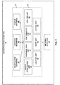
- FIG. 1 is a block diagram illustrating an example network environment that includes a disaster warning system.
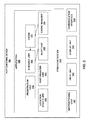
- FIG. 2 is a block diagram illustrating an example configuration of a coordination data center.
- FIG. 3 is a block diagram illustrating an example configuration of a participating device.
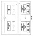
- FIG. 4 is a block diagram illustrating an example configuration of a router.
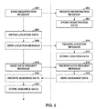
- FIG. 5 is a flowchart illustrating an example operation in which the participating device interacts with the coordination data center.
- FIG. 6 is a flowchart illustrating a continuation of the example operation of FIG. 5 .
- FIG. 7 is a flowchart illustrating a further continuation of the example operation of FIG. 5 .
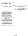
- FIG. 8 is a flowchart that illustrates an example operation in which the coordination data center and the router interact.
- FIG. 9 is a block diagram that illustrates an example effect of re-routing traffic.
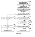
- FIG. 10 is a flowchart illustrating an example operation of a forwarding unit.
- FIG. 11 is a flowchart illustrating an example interaction between a client device and the coordination data center to display status data to a user.
- FIG. 12 is a flowchart illustrating an example interaction between the client device and the coordination data center to display post-disaster analysis data to a user.
- FIG. 13 illustrates an example interface presented by the participating device.
- FIG. 14 illustrates an example user interface presented by the participating device that prompts a user to indicate whether the user needs emergency assistance.
- FIG. 15 illustrates an example status review interface.
- FIG. 16 illustrates an example analysis interface
- FIG. 17 is a block diagram illustrating an example configuration of a computing device.
- FIG. 1 is a block diagram illustrating an example network environment that includes a disaster warning system 2.
- Disaster warning system 2 may warn users 4A-4N (collectively, "users 4") of an approaching disaster and advises users 4 how to avoid the disaster.
- disaster warning system 2 may collect information from users 4 after the disaster has affected an area.
- Disaster warning system 2 may use the collected data to help users 6A-6N (collectively, "users 6"), such as rescue crews, respond to the disaster or may help other users 6, such as friends and family, quickly determine the status of users 4 without risking overloading network infrastructure associated with the affected region.
- the disaster warning system 2 includes a set of participating devices 8A-8N (collectively, “participating devices 8"), a coordination data center 10, a set of client devices 12A-12N (collectively, “client devices 8"), and a network 14.
- Network 14 facilitates communication among participating devices 8, coordination data center 10, and client devices 12.
- Participating devices 8 enable users 4 to communicate with other computing devices via network 14.
- Each of participating devices 8 comprises one or more computing devices.
- participating devices 8 comprise various types of computing devices.
- participating devices 8 can comprise mobile devices, such as mobile telephones, smartphones, tablet computers, laptop computers, netbook computers, and other types of computing devices that enable their users to communicate with one or more other computing devices.
- one or more of participating devices 8 can comprise types of computing devices other than mobile computing devices, such as personal computers.
- FIG. 1 shows participating devices 8 as mobile telephones, readers will understand that participating devices 8 can comprise one or more other types of computing devices.
- Participating devices 8 are able to communicate with other computing devices on network 14 wirelessly. That is, each of participating devices 8 comprises a radio transmitter that sends wireless signals received by base stations 16. Base stations 16 transmit data represented by the wireless signals onto network 14 for delivery to destination devices. Furthermore, each of participating devices 8 comprises a radio receiver that receives wireless signals transmitted by base stations 16. The wireless signals transmitted by base stations 16 represent data sent by source devices on network 14 to participating devices 8.
- Coordination data center 10 may be provided by a data center having redundant computing devices coupled by a high-speed switch fabric and other devices.
- coordination data center 10 may represent one or more personal computers, standalone server devices, blade server devices, and/or other types of computing devices.
- Client devices 12 enable users 6 to communicate with other computing devices via network 14.
- Each of client devices 12 comprises one or more computing devices.
- client devices 12 can comprise various types of computing devices.
- client devices 12 can comprise mobile telephones, smartphones, tablet computers, laptop computers, desktop computers, netbook computers, thin-client computers, mainframe computers, in-car computers, network appliances, and other types of computing devices that enable users 6 to communicate with other computing devices via network 14.
- FIG. 1 shows client devices 12 as being laptop computers, readers will understand that client devices 12 can comprise one or more other types of computing devices.
- network 14 facilitate communication among participating devices 8, coordination data center 10, and client devices 12 in various ways.
- network 14 include various types of network.
- network 14 can include one or more local area networks, campus area networks, wide area networks, telephone communication networks, and/or other types of networks.
- Some examples of network 14 include the Internet.
- various examples of network 14 include various types of intermediate network devices.
- network 14 can include one or more routers, switches, hubs, bridges, firewall devices, and other types of intermediate network devices.
- the example of Figure 1 illustrates that network 14 comprises a set of routers 18A-18N (collectively, "routers 18"). Each of routers 18 comprises one or more computing devices that route data through network 14.
- Coordination data center 10 receives input from an emergency management authority 20.
- the input indicates that a disaster has struck or is about to strike a given area, such as a city, part of a city, county, or region.
- the input can indicate that an earthquake has struck a particular city or region.
- the input can indicate that a tornado is moving through a particular county.
- the input can indicate that a terrorist attack has struck a particular part of a city.
- Other example types of disasters can include tsunami, hurricane, storm surge, flood, volcanic eruption, nuclear meltdown, chemical, biological or nuclear weapons attack, wildfire, school shooting, or other types of events that in which the lives of many people are threatened.
- emergency management authority 20 includes various types of governmental or non-governmental authorities.
- emergency management authority 20 can be the National Weather Service, the United States Department of Homeland Security, the United States Geological Survey, the National Hurricane Center, law enforcement agencies, the National Forest Service, or another authority that is able to indicate whether a disaster has struck or is about to strike an area.
- coordination data center 10 When coordination data center 10 receives the input from emergency management authority 20 indicating that a disaster has affected or is about to affect a given area, coordination data center 10 sends disaster alert messages to participating devices 8 in the given area.
- participating devices 8 perform various actions in response to the disaster alert messages. For example, participating devices 8 can alert users 4 regarding the disaster. Furthermore, in this example, participating device 8 can inform users 4 how to best avoid harm from the disaster.
- participating devices 8 can send location data to coordination data center 10. The location data sent by participating devices 8 indicate locations of participating devices 8.
- coordination data center 10 may send reconfiguration messages to one or more routers 18 in network 14.
- routers 18 perform various actions in response to receiving the router reconfiguration messages. For example, routers 18 can prioritize the transmission of certain types of communications through network 14. For instance, routers 18 can prioritize communications sent and received by emergency response personnel, such as ambulance crews, firefighters, law enforcement officers, and so on. In another example, routers 18 can prioritize the transmission of messages sent from or to communication devices in the area affected by the disaster. In yet another example, routers 18 can reroute the transmission of data through network 14 such that traffic not destined for communication devices in the disaster area is not routed through parts of network 14 that are in the affected area.
- Coordination data center 10 may also receive post-disaster input from emergency management authority 20.
- the post-disaster input indicates that immediate danger from a disaster has passed or that the disaster has stopped actively affecting an area.
- coordination data center 10 can receive post-disaster input from emergency management authority 20 indicating that a hurricane has moved out of a given area.
- coordination data center 10 sends post-disaster messages to participating devices 8 in the affected area.
- participating devices 8 respond to the post-disaster messages in various ways. For example, participating devices 8 can respond to the post-disaster messages by prompting users 4 to indicate whether users 4 need emergency assistance. Emergency assistance can include medical assistance, firefighting assistance, law enforcement assistance, and/or other types of assistance needed urgently in the wake of a disaster. In this example, participating devices 8 provide status messages to coordination data center 10. The status messages indicate whether users 4 need emergency assistance. In another example, participating devices 8 can respond to the post-disaster messages by sending location data to coordination data center 10. The location data sent by participating devices 8 indicates new locations of participating devices 8.
- Coordination data center 10 provides a status data and location data for users 4 to client devices 12.
- coordination data center 10 can provide data indicating that user 4A is near 436 Canyon Road and does not need emergency assistance.
- users 6 use the status data and location data for various purposes.
- users 6 can use the status data and location data to learn locations of their friends or family are whether their friends or family need emergency assistance.
- users 6 can use the status data and location data to coordinate a response to the disaster.
- users 6 can use the status data and location data to send emergency response resources to areas having the greatest concentration of people needing assistance.
- users 6 include emergency response personnel.
- FIG. 2 is a block diagram illustrating a simplified arrangement of a coordination data center 10.
- coordination data center 10 is represented in a three tier arrangement having a network interface 40, a set of message processing units 42 executing on application servers, and a registration database 44, a location database 46, and a status database 48 maintained by one or more database servers 47.
- coordination data center may include high-speed switching components to interconnect network interface 40, the application servers and database servers 47.
- Network interface 40 provides front-end interface for receiving messages from and sending messages two network 14.
- network interface may include one or more web servers for presenting web-based interface for remote access, such as via users 6.
- network interface may communicate directly with mobile devices 4 via one or more communication protocols.
- Network interface 40 may interact with message processing units 42 to process certain types of messages received from network 14.
- message processing units 42 include a server registration unit 50, a location unit 52, a guidance data unit 54, an alert unit 56, a post-disaster unit 58, a status unit 60, and an analysis unit 62.
- Other examples include more, fewer, or different message processing units.
- server registration unit 50 processes registration messages received by network interface 40.
- Location unit 52 processes location messages received by network interface 40.
- Guidance data unit 54 processes guidance request messages received by network interface 40.
- Alert unit 56 processes disaster input messages received by network interface 40.
- Post-disaster unit 58 processes post-disaster input messages received by network interface 40.
- Status unit 60 processes status messages received by network interface 40.
- Analysis unit 62 processes analysis request messages received by network interface 40.
- coordination data center 10 implements network interface 40 and message processing units 42 in various ways.
- execution of instructions by circuitry, such as a processing system, in a computing device can cause the computing device to provide network interface 40 and one or more of message processing units 42.
- a computing device can comprise one or more application-specific integrated circuits (ASICs) that operate to provide network interface 40 and/or message processing units 42.
- ASICs application-specific integrated circuits
- coordination data center 10 implements registration database 44, location database 46, and status database 48 in various ways.
- registration database 44, location database 46, and status database 48 can be implemented as one or more types of databases.
- registration database 44, location database 46, and status database 48 can be implemented as one or more relational databases, files, directories, XML documents, or other types of data structures for storage and retrieval of data.
- registration database 44, location database 46, and status database 48 are implemented as parts of a single database.
- FIG. 3 is a block diagram illustrating an example configuration of a participating device 8A. Although the example of FIG. 3 illustrates an example configuration of participating device 8A, readers will understand that other ones of participating devices 8 can have similar configurations. Moreover, readers will understand that other ones of participating devices 8 can have different configurations than the configuration of participating device 8A illustrated in the example of FIG. 3 .
- participating device 8A implements a geopositioning unit 140, an input unit 142, a display unit 144, a communication interface 146, an operating system 148, and an application 150.
- the geopositioning unit 140 provides location data that indicates a geographical location of participating device 8A.
- Input unit 142 receives input from user 4A.
- Display unit 144 displays data to user 4A.
- Communication interface 146 sends data to and receives data from network 14 wirelessly.
- Operating system 148 manages resources of participating device 8A.
- Application 150 runs on participating device 8A and provides disaster alert functionality. In some examples, application 150 runs in the background of participating device 8A and does not request the attention of user 4A until participating device 8A receives a message from coordination data center 10. Moreover, although shown separately, all or portions of application 150 may be integrated within operating system 148.
- Application 150 comprises a registration unit 152, a location update unit 153, a cache manager 154, a cache 156, an alert unit 158, a guidance unit 160, and a post-disaster unit 162. In some examples, application 150 includes more, fewer, or different units.
- communication interface 146 receives a message for application 150
- operating system 148 provides the message to application 150.
- application 150 utilizes geopositioning unit 140, input unit 142, display unit 144, or communication interface 146
- application 150 provides requests to operating system 148.
- Operating system 148 then interacts with geopositioning unit 140, input unit 142, display unit 144, or communication unit 146 to fulfill the requests.
- registration unit 152 registers information about user 4A with coordination data center 10. In this way, coordination data center 10 may have access to information that may be used in the prior to or during the aftermath of a natural disaster or other event.
- Location update unit 153 repeatedly sends information indicating the location of participating device 8A to coordination data center 10. In this way, coordination data center 10 is able to store data indicating the current location of participating device 8A. In some examples, alert unit 56 uses this data to determine whether participating device 8A is in an area potentially affected by a disaster.
- cache manager 154 Prior to participating device 8A receiving a disaster alert message, cache manager 154 downloads guidance data to participating device 8A. Cache manager 154 caches the guidance data in cache 156. In some examples, the guidance data provides information about locations for user 4A to go to when a disaster is approaching. As participating device 8A moves to different areas, cache manager 154 can download different guidance data.
- alert unit 158 When communication interface 146 receives a disaster alert message from communication server 10, communication interface 146 provides the disaster alert message to alert unit 158. Alert unit 158 then generate response instructions. The response instructions indicate how user 4A may respond to the disaster. Guidance data stored in cache 156 can be used to generate the response instructions. In some examples, alert unit 158 determines whether the disaster alert message is related to a disaster that can be avoided by moving to another location. If so, alert unit 158 instructs guidance unit 160 to calculate a route to a safe location. In such examples, the response instructions can include the calculated route.
- alert unit 158 generates a disaster alert interface when alert unit 158 receives a disaster alert message.
- Alert unit 158 instructs operating system 148 to display the disaster alert interface on display unit 144.
- the disaster alert interface displays the information about a disaster affecting the location of participating device 8A and the response instructions.
- alert unit 158 When alert unit 158 receives a disaster alert message, alert unit 158 sends a request to geopositioning unit 140 to provide location data to alert unit 158.
- the location data indicates a geographical location of participating device 8A.
- Alert unit 158 then generates a location message based on the location data.
- the location message specifies the location of participating device 8A.
- Alert unit 158 then sends the location message to coordination data center 10.
- coordination data center 10 can store data indicating a location of participating device 8A at the time coordination data center 10 sent the disaster alert message, (e.g., prior to the disaster striking an area.)
- post-disaster unit 162 When communication interface 146 receives a post-disaster message, post-disaster unit 162 performs a post-disaster operation. In various examples, post-disaster unit 162 performs various post-disaster operations. For example, post-disaster unit 162 can perform a post-disaster operation in which post-disaster unit 162 obtains location data from geopositioning unit 140. In this example, post-disaster system generates a location message based on the location data. The location message specifies the location of participating device 8A. Post-disaster unit 162 then sends the location message to coordination data center 10. In this way, coordination data center 10 can store data indicating the location of participating device 8A after a disaster has struck an area.
- post-disaster unit 162 generates a status interface.
- the status interface prompts user 4A to indicate whether user 4A needs emergency assistance.
- Post-disaster unit 162 then instructs operating system 148 to display the status interface on display unit 144.
- input unit 142 can receive input from user 4A indicating whether user 4A needs emergency attention.
- post-disaster unit 162 When input unit 142 receives the input, post-disaster unit 162 generates a status message that indicates whether user 4A needs emergency assistance.
- Post-disaster unit 162 then instructs operating system 148 to send the status message to coordination data center 10.
- Operating system 148 uses communication interface 148 to send the status message to coordination data center 10.
- FIG. 4 is a block diagram that illustrates an example configuration of router 18A. Although the example of FIG. 4 illustrates an example configuration of router 18A, readers will understand that other ones of routers 18 can have similar configurations. Moreover, readers will understand that other ones of routers 18 can have configurations different than the configuration of router 18A illustrated in the example of FIG. 4 .
- router 18A comprises a routing plane 170, a forwarding plane 172, and communication system 174.
- Routing plane 170 provides a routing engine 176, a routing information base (RIB) 178, a disaster unit 180, and a disaster profile 182.
- Forwarding plane 172 comprises a set of forwarding units 184A-184N (collectively, "forwarding units 184").
- Forwarding units 184A-184N respectively comprise forwarding information bases (FIBs) 186A-186N (collectively, "FIBs 186"), interface cards (IFCs) 188A-188N (collectively, "IFCs 188”), and forwarding circuitry 190A-190N (collectively, "forwarding circuitry 190").
- Communication system 174 facilitates data transfer between forwarding units 184 and between control plane 172 and forwarding units 184.
- Routing engine 176 has primary responsibility for maintaining RIB 178 to reflect the current topology of network 14 and other network entities to which router 18A is connected.
- routing engine 176 provides an operating environment for execution of protocols that communicate with peer routers and periodically update RIB 178 to accurately reflect the topology of the network and the other network entities.
- Example protocols include routing and label switching protocols, such as mpBGP, ISIS, RSVP-TE, and LDP. These protocols are usable to establish virtual private networks (VPNs), to establish label-switched paths (LSPs), and to exchange labels.
- Routing engine 176 typically processes RIB 178 to perform route selection and to generate forwarding rules.
- FIBs 186 store the forwarding rules generated by routing engine 176.
- IFCs 188 in forwarding units 184 receive packets from different network links.
- forwarding circuitry 190 uses the forwarding rules in FIBs 186 to identify and perform actions with regard to the packets. For example, forwarding circuitry 190A can use the forwarding rules in FIB 186A to determine that a packet is to be forwarded to a particular one of forwarding units 184. In another example, forwarding circuitry 190A can use the forwarding rules in FIB 186A to determine that a packet is to be dropped. In yet another example, forwarding circuitry 190A can use the forwarding rules in FIB 186A to forward a packet received in IFC 188A to routing plane 170.
- disaster unit 180 receives reconfiguration messages from coordination data center 10.
- disaster unit 180 executing within routing plane 170 performs actions that can adjust the bandwidth available for a particular use, such as use by emergency response personnel.
- disaster unit 180 may use information stored in disaster profile 182 to modify data in RIB 178.
- Routing engine 176 processes the modified data in RIB 178 to perform route selection again and to regenerate forwarding rules.
- Routing engine 176 then causes FIBs 186 to store the regenerated forwarding rules.
- router 18A can change how router 18A routes packets such that router 18A may, in effect, adjust the bandwidth available for a particular use, such as use by emergency response personnel, during and after the disaster.
- router 18A implements routing engine 176, RIB 178, disaster unit 180, disaster profile 182, FIBs 186, IFCs 188, and forwarding circuitry 190 in various ways.
- execution of instructions by circuitry can cause router 18A to implement functionality of routing engine 176, and disaster unit 180.
- router 18A can comprise one or more ASICs that operate to provide functionality of forwarding circuitry 190, IFCs 188, routing engine 176, and/or disaster unit 180.
- RIB 178 and FIBs 186 are implemented using various types of computer storage media, such as registers, cache memory units, random-access memory units, and/or other types of devices for storage and retrieval of data.
- FIG. 5 is a flowchart illustrating an example operation in which participating device 8A interacts with coordination data center 10. Although the example of FIG. 5 illustrates an example operation of participating device 8A, readers will understand that other ones of participating devices 8 can perform similar operations. Moreover, readers will understand that other ones of participating devices 8 can perform different operations.
- registration unit 152 causes communication interface 146 to send a registration message to coordination data center 10 (200).
- the registration message comprises registration data.
- the registration data includes various types of data.
- the registration data can include a name, home address, phone number, emergency contact information, medical information such as blood type and allergies, and other information about user 4A.
- registration unit 152 formats the registration message in various ways. For instance, some examples of registration unit 152 format the registration message as a Hypertext Transfer Protocol HTTP message. Other examples of registration unit 152 format the registration message as a remote procedure call (RPC) protocol message.
- RPC remote procedure call
- network interface 40 of coordination data center 10 receives the registration message (202).
- network interface 40 uses server registration unit 50 to store the registration data specified by the registration message in registration database 44. In this way, coordination data center 10 can store information regarding user 4A that may be useful in the aftermath of a disaster.
- registration unit 152 formats the registration message in various ways. For instance, some examples of registration unit 152 format the registration message as a HTTP message. Other examples of registration unit 152 format the registration message as a RPC message.
- location update unit 153 obtains location data from geopositioning unit 140 (206).
- the location data indicates a current location of participating device 8A.
- geopositioning unit 140 determines the current geographical location of participating device 8A in various ways.
- geopositioning unit 140 can use the Global Positioning System (GPS), the Galileo navigation system, the Glonass navigation system, or another satellite-based navigation system.
- GPS Global Positioning System
- Galileo navigation system the Galileo navigation system
- Glonass navigation system the Glonass navigation system
- another satellite-based navigation system another satellite-based navigation system.
- Location update unit 153 then causes communication interface 146 to send a location message to coordination data center 10 (208).
- the location message contains data indicating the current location of participating device 8A.
- the location message specifies the current geographical location of participating device 8A in various ways.
- the location message can specify the current geographical location of participating device 8A in terms of latitude and longitude.
- the location message can specify the current location of participating device 8A as a closest street address to participating device 8A.
- location update unit 153 sends the location messages to coordination data center 10 in response to various events. For instance, some examples of location update unit 153 send location messages to coordination data center 10 on a periodic basis. Other examples of location update unit 153 send location messages to coordination data center 10 upon detecting that participating device 8A has moved more than a given distance from the location indicated in a location message previously sent by location update unit 153. In some examples, location update unit 153 sends location messages as part of a background process. In other words, location update unit 153 can send location messages without first receiving explicit input from user 4A to do so.
- location update unit 153 does not send location messages to coordination data center 10 after participating device 8A has received a disaster alert message from the coordination data center 10. Because location update unit 153 does not send location messages to coordination data center 10 after participating device 8A has received a disaster alert message from the coordination data center 10, resources of network 14 are not devoted to forwarding the location messages. In some instances, such resources of network 14 could be better used for other purposes, such as forwarding disaster alert messages and forwarding communication data between emergency response personnel.
- location update unit 153 formats the location message in various ways. For instance, some examples of location update unit 153 format the location message as a HTTP message. Other examples of location update unit 153 format the location message as a RPC message.
- coordination data center 10 receives the location message (210).
- network interface 40 uses location unit 52 to store data indicating the location participating device 8A specified by the location message in location database 46 (212).
- cache manager 154 causes communication interface 146 to periodically send a data request message to coordination data center 10 to receive any impending guidance (214). That is, the data request message requests any recent guidance data from coordination data center 10.
- application 150 combines a registration message, a location message, and/or a data request message into a single message.
- cache manager 154 formats the data request message in various ways. For instance, some examples of cache manager 154 format the data request message as a HTTP message. Other examples of cache manager 154 format the data request message as a RPC message.
- cache manager 154 sends the data request message to coordination data center 10 in response to various events. For instance, some examples of cache manager 154 send data request messages to coordination data center 10 on a periodic basis. Other examples of cache manager 154 send data request messages to coordination data center 10 upon detecting that participating device 8A has moved more than a given distance from the location at which a location message was previously sent by location update unit 153.
- coordination data center 10 receives the data request message (216). For example, when coordination data center 10 receives the data request message, guidance data unit 54 sends guidance data to participating device 8A based on the particular location information for the device (218). Alternatively, coordination data center 10 may periodically or asynchronously push guidance data to participating device 8A based on the most recent location data received from the mobile device.
- the guidance data includes various types of data.
- the guidance data can specify the names and locations of places near a location of participating device 8A where people can go to avoid various types of disasters. For instance, in this example, the guidance data can specify the names and locations of nearby fallout shelters where people can go to avoid nuclear fallout.
- the guidance data can include road maps, topological maps, and/or other types of maps of an area surrounding participating device 8A. In this example, the guidance data can also include information regarding traffic conditions on the roads, road closures, and other information regarding road conditions.
- Cache manager 154 of participating device 8A receives the guidance data sent by coordination data center 10 (220) and stores the guidance data in cache 156 (222). In some examples, cache manager 154 does not send data request messages after participating device 8A has received a disaster alert message from the coordination data center 10. Because cache manager 154 does not send data request messages after participating device 8A has received a disaster alert message from coordination data center 10, resources of network 14 are not devoted to forwarding the data request messages and guidance data. In some instances, such resources of network 14 could be better used for other purposes, such as forwarding disaster alert messages and forwarding communication data between emergency response personnel. In this way, bandwidth available for other uses may be adjusted.
- coordination data center 10 receives disaster input from emergency management authority 20 (230).
- coordination data center 10 receives the disaster input in various ways.
- coordination data center 10 can provide a secure website for authorized personnel.
- employees of emergency management authority 20 can use web browsers running on computing devices to access the website. Web pages in the website include features that the employees can use to provide the disaster input to coordination data center 10.
- coordination data center 10 can provide a command line interface.
- employees of emergency management authority 20 can provide the disaster input to coordination data center 10 by entering one or more commands into the command line interface.
- the disaster input includes various types of information.
- the disaster input can specify a type of disaster (e.g., hurricane, flood, shooting, etc.).
- the disaster input can specify details regarding the disaster.
- the disaster input can identify an area affected by the disaster.
- the disaster input can identify areas likely to be affected by the disaster in the future.
- alert unit 56 After coordination data center 10 receives the disaster input from emergency management authority 20, alert unit 56 identifies applicable mobile devices (232).
- the applicable mobile devices include ones of participating devices 8 that are in an area affected by the disaster or areas likely to be affected by the disaster.
- alert unit 56 uses location data stored in location database 46 to identify applicable mobile devices.
- Alert unit 56 then sends disaster alert messages to the applicable participating devices 8 (234).
- alert unit 56 formats the disaster alert messages in various ways. For example, alert unit 56 can format the disaster alert messages as one or more HTTP messages. In another example, alert unit 56 can format the disaster alert messages as one or more SMS text messages.
- the disaster alert messages comprise various data.
- the disaster alert messages can comprise data that identifies a type of the disaster.
- the disaster alert message can comprise data indicating a direction in which the disaster is moving.
- the amount of data in the disaster alert messages is kept relatively small. In this way, the disaster alert messages contribute less to the load on network 14 during the disaster.
- participating device 8A receives a disaster alert message (236).
- alert unit 158 obtains location data from geopositioning unit 140 (238). The location data specifies a current geographical location of participating device 8A. Alert unit 158 then sends a location message to coordination data center 10 (240). The location message specifies the current geographical location of participating device 8A.
- coordination data center 10 receives the location message (242). In this way, coordination data center 10 receives data indicating a location of participating device 8A.
- network interface 40 uses location unit 52 to store data in location database 46 indicating the location of participating device 8A (244). The location data stored by Location unit 52 in location database 46 is based on data specified by the location message.
- alert unit 158 generates and sends the location message automatically, without input from user 4A, in response to receiving the disaster alert message. In this way, coordination data center 10 may be able to store data indicating a location of participating device 8A without user 4A needing to instruct participating device 8A to provide the location data to coordination data center 10.
- alert unit 158 After alert unit 158 receives the disaster alert message, alert unit 158 generates response instructions (246).
- the response instructions indicate how user 4A should respond to the disaster.
- Alert unit 158 generates different types of response instructions for different types of disasters. For example, alert unit 158 can generate response instructions for a tornado that instruct the user 4A to seek shelter in a basement, interior windowless room, or, if user 4A is outside and cannot reach a building, in a ditch or culvert. In another example, alert unit 158 can generate response instructions for a biological weapons attack that instruct user 4A to stay indoors and seal off windows and doors.
- alert unit 158 determines whether the disaster is one that user 4A can escape by moving to a different location. For example, user 4A may be able to escape from a tornado, wildfire, tsunami, lahar, hurricane, typhoon, nuclear fallout, volcanic eruption, or another type of disaster by moving to a different location. In contrast, user 4A may be unable to escape from a terrorist or military attack, school shooting, earthquake, landslide, train derailment, plane crash, shipwreck, or other types of disasters simply by moving to a different location.
- alert unit 158 determines in various ways whether the disaster is one that user 4A can escape by moving to a different location. For example, some examples of alert unit 158 use information specified by the disaster alert message to determine whether the disaster is one that user 4A can escape by moving to a different location.
- the escape route is a series of instructions that indicate where user 4A should go in order to escape the disaster.
- the escape route can be a series of turn-by-turn directions that indicate how user 4A should get to a place of safety.
- the disaster alert message indicates a direction in which the disaster is moving.
- the disaster alert message can indicate that a wildfire is spreading eastward along a given highway.
- the disaster alert message can indicate that a tsunami is headed inland along a certain valley.
- the disaster alert message can indicate that a flood caused by a dam or levee breach is moving in a given direction.
- guidance unit 160 calculates the escape route based on the direction in which the disaster is moving. In this way, guidance unit 160 might not instruct user 4A to go to a location that will be in the path of the disaster.
- guidance unit 160 uses guidance data stored in cache 156 to generate the response instructions.
- cache 156 can store instructions for responding to a tornado.
- guidance unit 160 generates the response instructions for a tornado based on the instructions stored in cache 156.
- cache 156 can store maps.
- guidance unit 160 uses the maps to generate an escape route from a current location of participating device 8A to a location where user 4A can escape the disaster.
- cache 156 can store data regarding road conditions.
- guidance unit 160 can use the road conditions when generating the escape route. In this way, the directions might not guide user 4A onto blocked or congested roads.
- alert unit 158 causes display unit 144 to display disaster information (248).
- the disaster information includes the response instructions.
- the disaster information includes various types of information.
- the disaster information can include a description of the disaster.
- the disaster information can include turn-by-turn directions for moving to a different location.
- alert unit 158 causes display unit 144 to display the disaster information in various ways.
- alert unit 158 can cause display unit 144 to display various user interfaces that contain the disaster information.
- FIG. 13 illustrated in detail elsewhere in this disclosure, illustrates an example interface that contains the disaster information.
- coordination data center 10 receives post-disaster input from emergency management authority 20 (250).
- Coordination data center 10 can receive the post-disaster input after the disaster has stopped actively affecting the area. For example, if the disaster is a tornado, coordination data center 10 can receive the post-disaster input after the tornado has dissipated or left the area. In another example, if the disaster is a mass shooting, the coordination data center 10 can receive the post-disaster input after the situation is controlled.
- coordination data center 10 receives the post-disaster input in various ways.
- coordination data center 10 can provide a website.
- employees of emergency management authority 20 can use web browsers running on computing devices to access the website. Web pages in the website include features that the employees can use to provide the post-disaster input to coordination data center 10.
- coordination data center 10 can provide a command line interface.
- employees of emergency management authority 20 can provide the post-disaster input to coordination data center 10 by entering one or more commands into the command line interface.
- post-disaster unit 58 After coordination data center 10 receives the post-disaster input, post-disaster unit 58 identifies applicable mobile devices (252). The applicable mobile devices include ones of participating devices 8 in the affected area. In some examples, post-disaster unit 58 uses data in location database 46 to identify participating device 8 in the area indicated by the post-disaster input. Post-disaster unit 58 then sends post-disaster messages to participating devices 8 in the area indicated by the post-disaster input (254).
- client 8A receives one of the post-disaster messages from coordination data center 10 (256).
- post-disaster unit 162 of participating device 8A obtains location data from geopositioning unit 140 (258).
- Post-disaster unit 162 sends a location message to coordination data center 10 (260).
- the location message specifies the location data.
- coordination data center 10 receives the location message (262).
- location unit 52 of coordination data center 10 stores the location data specified by the location message in location database 46 (264).
- participating device 8A sends and coordination data center 10 receives new location data indicating a new location of participating device 8A.
- Receiving location data from participating devices 8 before and after a disaster strikes an area can be advantageous for several reasons. For example, some of users 4 may be killed or seriously injured in the disaster and their mobile devices may be destroyed in the disaster. Consequently, it may only be possible to collect location data before the disaster affects the area. At the same time, it may be helpful to emergency response personnel and others users 6 to know the locations of users 4 after the disaster has stopped actively affecting the area so that emergency response personnel or others can know where to go to help users 4.
- post-disaster unit 162 prompts user 4A to indicate a status (266).
- post-disaster unit 162 can prompt user 4A to indicate whether user 4A needs emergency assistance.
- post-disaster unit 162 prompts user 4A to indicate whether user 4A needs emergency assistance in various ways.
- post-disaster unit 162 can cause display unit 144 to display a user interface that contains instructions that request user 4A to indicate whether user 4A needs emergency assistance.
- the user interface has various appearances.
- FIG. 14 illustrated in detail elsewhere in this disclosure, illustrates an example user interface that prompts user 4A to indicate whether user 4A needs emergency assistance.
- post-disaster unit 162 After post-disaster unit 162 prompts user 4A to indicate a status, post-disaster unit 162 receives status input from user 4A (268). The status input indicates whether user 4A needs emergency assistance. After post-disaster unit 162 receives the status input from user 4A, post-disaster unit 162 sends a status message to coordination data center 10 (270). The status message indicates whether user 4A needs emergency assistance.
- the status message can include additional information that indicates what type of emergency assistance user 4A needs.
- the status message can include information indicating that user 4A needs emergency medical assistance.
- the status message can include information indicating that user 4A needs emergency firefighting assistance.
- the status message can include information indicating that user 4A needs emergency law enforcement assistance. User 4A may need emergency law enforcement assistance in various situations, such as when looting breaks out in the wake of a disaster.
- post-disaster unit 162 formats the status message in various ways. For example, post-disaster unit 162 can format the status message as one or more HTTP messages. In another example, post-disaster unit 162 can format the status message as one or more SMS messages.
- coordination data center 10 receives the status message from participating device 8A (272).
- network interface 40 uses status unit 60 to store the status of user 4A in status database 48 (274).
- post-disaster unit 58 stores the status of user 4A in status database 48 in various ways.
- status database 48 can comprise one or more XML documents.
- status database 48 can store the status of user 4A as one or more XML elements in the one or more XML documents.
- status database 48 can comprise a relational database.
- post-disaster unit 58 stores the status of user 4A as one or more records in one or more tables of the relational database.
- FIG. 8 is a flowchart that illustrates an example operation in which coordination data center 10 and router 18A interact. Although the example of FIG. 8 illustrates an example operation of router 18A, readers will understand that other ones of routers 18 can perform similar operations. Moreover, readers will understand that other ones of routers 18 can perform different operations. Furthermore, in other examples, a server separate from the server that interacts with participating devices 8 interacts with routers 18.
- router 18A receives disaster profile 182 (300).
- router 18A receives disaster profile 182 from various sources.
- router 18A can receive disaster profile 182 from coordination data center 10 using, for example, a configuration protocol (e.g.,. SNMP) or a routing protocol (e.g., the Border Gateway Protocol) that has been extended to include disaster profile 182 in NLRI information.
- a configuration protocol e.g.,. SNMP
- a routing protocol e.g., the Border Gateway Protocol
- router 18A can receive disaster profile 182 from a computing device used by emergency management authority 20 using other types of protocols.
- Disaster profile 182 includes various data, such as data indicating sets of IP addresses associated with particular areas.
- disaster profile 182 can include data indicating sets of IP addresses associated with a particular area affected by a disaster.
- disaster profile 182 can include data indicating sets of IP addresses associated with emergency response authorities.
- disaster profile 182 can include data that associates IP addresses of routers 18 with geographical locations of routers 18.
- router 18A may receive disaster profile 182 at various times. For instance, in the example of FIG. 8 , router 18A receives disaster profile 182 prior to router 18A receiving a reconfiguration message from coordination data center 10. In another example, router 18A receives disaster profile 182 along with or within the reconfiguration message. In yet another example, router 18A sends a request for disaster profile 182 after receiving the reconfiguration message. In this example, router 18A receives disaster profile 182 in response to the request.
- router 18A After router 18A receives disaster profile 182, router 18A stores disaster profile 182 (302). In various examples, router 18A stores disaster profile 182 in various formats. For example, router 18A can store disaster profile 182 as one or more XML documents, records in one or more relational databases, or in one or more other formats.
- Coordination data center 10 receives disaster input from emergency management authority 20 (304). As discussed above with regard to the example of FIG. 6 , coordination data center 10 can receive the disaster input from emergency management authority 20 in various ways. After coordination data center 10 receives the disaster input, alert unit 56 sends reconfiguration messages to routers 18 (306).
- the reconfiguration messages include various types of data.
- the reconfiguration messages can include data indicating an area affected by the disaster.
- the reconfiguration messages can include lists of routers in an area affected by the disaster.
- the reconfiguration messages can include data that indicate amounts of time that routers 18 are to use disaster profile 182.
- alert unit 56 formats the disaster reconfiguration message in various ways. For example, alert unit 56 formats the disaster reconfiguration message as a HTTP request. In another example, alert unit 56 formats the disaster reconfiguration message as a RPC protocol message.
- router 18A receives one of the reconfiguration messages (308).
- a series of one or more packets addressed to router 18A contains the reconfiguration message.
- FIBs 186 include forwarding rules that instruct forwarding units 184 to forward packets addressed to router 18A to routing plane 170. In this way, disaster unit 180 receives the reconfiguration message.
- disaster unit 180 loads data from disaster profile 182 (310).
- disaster unit 180 loads various types of data from disaster profile 182.
- the reconfiguration message can specify that a disaster is about to affect or has affected a given area.
- disaster profile 182 can include data indicating IP addresses of routers in various areas.
- disaster unit 180 can load the IP addresses of routers in the given area.
- disaster unit 180 modifies RIB 178 based on the data loaded from disaster profile 182 (312).
- disaster profile 182 modifies RIB 178 in various ways.
- the reconfiguration message can indicate that certain ones of routers 18 are disabled because of the disaster.
- disaster unit 180 modifies RIB 178 such that RIB 178 does not specify routes through routers 18 that are disabled by the disaster. Accordingly, router 18A may not need to consume time determining that particular ones of routers 18 are disabled. Consequently, router 18A may be able to route packets by alternate routes more quickly.
- disaster unit 180 can modify RIB 178 such that RIB 178 does not route traffic destined for computing devices outside an area affected by the disaster through routers 18 in the area affected by the disaster. In this way, the resources of routers 18 in the affected area are not consumed by transferring packets that are not destined for or generated in the affected area. Consequently, routers 18 in the affected area may be able to route packets destined for or generated in the affected area more quickly.
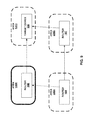
- FIG. 9 is a block diagram that illustrates an example effect of re-routing traffic.
- router 18A is located in an area 330A
- router 18B is located in an area 330B
- router 18C is located in an area 330C
- a target device 332 is located in an area 330D.
- router 18A is initially configured to route packets destined for target device 332 through router 18B.
- router 18A can receive a reconfiguration message that indicates that a disaster is about to affect or has affected area 330B.
- disaster unit 180 can modify RIB 178 such that router 18A routes packets destined for target device 332 through router 18C instead of through router 18B. In this way, packets destined for target device 332 continue to reach target device 332 even though the packets may pass through a more expensive (e.g., slower) route.
- routing engine 176 After disaster unit 180 modifies data in RIB 178, routing engine 176 generates modified forwarding rules (314). Routing engine 176 generates the modified forwarding rules based at least in part on data in RIB 178. After routing engine 176 generates the modified forwarding rules, routing engine 176 causes FIBs 186 to store the modified forwarding rules (316). As described with regard to the example of FIG. 10 , forwarding units 184 use the modified forwarding rules to determine how to forward packets received by forwarding units 184.
- FIG. 10 is a flowchart illustrating an example operation of forwarding unit 184A. Although the example of FIG. 10 illustrates an example operation of forwarding unit 184A, readers will understand that other ones of forwarding units 184 can perform similar operations. Moreover, readers will understand that other ones of forwarding units 184 can perform different operations.
- Forwarding unit 184A receives modified forwarding rules from routing engine 176 (350). After receiving the modified forwarding rules, forwarding unit 184A stores the modified forwarding rules in FIB 186A (352).
- IFC 188A of forwarding unit 184A receives a packet from network 14 (354). After receiving the packet, forwarding unit 184A applies the forwarding rules stored in FIB 186A to the packet. In the example of FIG. 10 , applying the forwarding rules stored in FIB 186A causes forwarding unit 184A to perform a series of steps to determine whether to assign high priority to the packet.
- forwarding unit 184A first determines whether the payload of the packet belongs to an essential protocol (356).
- the forwarding rules indicate that various protocols are essential or non-essential protocols.
- the forwarding rules can indicate that protocols used by emergency response personnel are essential protocols.
- the forwarding rules can indicate that a protocol carrying messages to and from coordination data center 10 is an essential protocol.
- the forwarding rules can indicate that a protocol for carrying voice or video data is a non-essential protocol.
- the forwarding rules can indicate that a protocol for carrying video game data is a non-essential protocol.
- forwarding unit 184A assigns high priority to the packet (358). In various examples, assigning high priority to the packet can have various results. For example, each of forwarding units 184 can have multiple queues. When forwarding units 184 receive a packet from other ones of forwarding units 184 or from routing plane 170, forwarding units 184 add the packet to one of these queues. Forwarding units 184 send packets on network 14 by selecting packets from the queues and then sending the selected packets. In this example, the queues are associated with different priority levels. Forwarding units 184 can disproportionately select packets from queues associated with high priority levels.
- forwarding units 184 may forward packets in the queues associated with high priority levels sooner than packets in queues associated with low priority levels. In this way, the throughput of router 18A is greater for packets in high priority queues than for packets in low priority queues.
- forwarding unit 184A can assign a high priority to the packet by attaching a flag to the packet.
- the other forwarding unit 184 places the packet in a high priority queue because the flag is attached to the packet.
- forwarding unit 184A determines whether either the source address or the destination address of the packet is in a set of addresses associated with emergency response personnel (360). If the source or destination address of the packet is in a set of addresses associated with emergency response personnel ("YES" of 360), forwarding unit 184A assigns high priority to the packet (358). In this way, the emergency response personnel may be able to send and receive data over network 14 more quickly.
- forwarding unit 184A determines whether a destination address of the packet is in a set of addresses associated with an area affected by the disaster (362). If the destination address of the packet is not in a set of addresses associated with the area affected by the disaster ("NO" of 362), forwarding unit 184A determines whether the source address of the packet is within a set of addresses associated with the area affected by the disaster (364). If either the source address of the packet is within the set of addresses associated with the affected area (“YES" of 358) or the destination address of the packet is within the set of addresses associated with the affected area (“YES" of 356), forwarding unit 184A drops the packet (366).
- forwarding unit 184A does not forward the packet. In this way, forwarding unit 184A does not contribute to the utilization of the network infrastructure in the affected area for non-essential packets. In this way, forwarding unit 184A may, in effect, adjust the bandwidth available for other uses, such as increasing the bandwidth available for use by emergency response personnel.
- forwarding unit 184A uses the forwarding rules in FIB 186A to identify a forwarding target for the packet (368). For example, forwarding unit 184A can use the forwarding rules in FIB 186A to determine that the packet is to be forwarded from forwarding unit 184N. Forwarding unit 184A also uses the forwarding rules in FIB 186A to identify the forwarding target for the packet after forwarding unit 184A assigns a high priority to the packet.
- forwarding unit 184A forwards the packet to the forwarding target (370). For example, if forwarding unit 184N is the forwarding target, forwarding unit 184 forwards the packet to forwarding unit 184N.
- forwarding unit 184 applies other forwarding rules.
- forwarding unit 184A can apply forwarding rules that drop packets for initiating phone calls to devices within the affected area, but do not drop packets for initiating phone calls by devices within the affected area.
- forwarding unit 184A can apply forwarding rules that prioritize traffic to and from devices in the affected area.
- FIG. 11 is a flowchart illustrating an example interaction between client device 12A and coordination data center 10 to display status data to user 6A.
- FIG. 11 illustrates an example operation of client device 12A, readers will understand that other ones of client devices 12 can perform similar operations. Moreover, readers will understand that other ones of client devices 12 can perform different operations. Furthermore, in other examples, client devices 12 can perform similar operations with regard to a server separate from the server that receives location data and status data from participating devices 8.
- client device 12A sends a status request message to coordination data center 10 (400).
- the status request message comprises a request to learn a post-disaster status of one or more of users 4.
- client device 12A sends the status request message in response to various events.
- client device 12A can send the status request message to coordination data center 10 in response to user 6A selecting one or more controls in a web page displayed by client device 12A.
- client device 12A can send the status request message as a HTTP message.
- client device 12A can send the status request message to coordination data center 10 as an SMS message.
- coordination data center 10 receives the status request message (402). After receiving the status request message, network interface 40 of coordination data center 10 uses analysis unit 62 to generate one or more status response messages to client device 12A (404). Network interface 40 sends the one or more status response message to client device 12A (406).
- the status response messages include various types of data.
- the one or more status response messages contain data that indicate the names, locations, and statuses of one or more of users 4.
- the status response message has various formats.
- the status response message can comprise data that represents a web page that specifies the post-disaster status of one or more of users 4.
- the status response message can be a SMS message.
- Client device 12A receives the one or more status response messages after network interface 40 sends the one or more status response messages (408). After receiving the status response messages, client device 12A processes data in the status response messages to display statuses of one or more of users 4 (410). In various examples, client device 12A can display the post-disaster statuses of users 4 in various ways. For example, client device 12A can display a notification window containing the post-disaster statuses of users 4. In another example, client device 12A can display a webpage containing the statuses of users 4.
- FIG. 15 illustrated in detail elsewhere in this disclosure, illustrates an example status review interface that lists names, statuses, and locations of users 4.
- users 6 can learn from coordination data center 10 whether particular ones of users 4 are in need of assistance. Because users 6 can learn whether particular ones of users 4 are in need of assistance, it may be unnecessary for users 6 to make phone call to users 4. Furthermore, it may be unnecessary for users 4 in the area affected by the disaster to make phone calls to users 6. As a result, the communications infrastructure in the affected area may not be overloaded with phone calls. Consequently, more resources of the communications infrastructure may be free to handle communications between emergency response personnel.
- FIG. 12 is a flowchart illustrating an example interaction between client device 12A and coordination data center 10 to display post-disaster analysis data to user 6A.
- FIG. 12 illustrates an example operation of client device 12A, readers will understand that other ones of client devices 12 can perform similar operations. Moreover, readers will understand that other ones of client devices 12 can perform different operations.
- Analysis unit 62 of coordination data center 10 performs a post-disaster analysis (450).
- analysis unit 62 uses data in registration database 44, location database 46, and status database 48, and/or other data sources to perform the post-disaster analysis.
- analysis performs various types of post-disaster analysis.
- analysis unit 62 can use data in registration database 44, location database 46, and status database 48 to identify areas where users 4 who need emergency assistance are concentrated.
- analysis unit 62 can assume that users 4 who did not respond to prompting to indicate whether they need emergency assistance in fact need emergency assistance.
- concentrations may be associated with areas especially hard hit by the disaster. By identifying such concentrations, analysis unit 62 may be able to assist emergency response personnel allocate their resources.
- analysis unit 62 can use data in registration database 44, location database 46, and status database 48 to assemble lists of missing people. Emergency response personnel may try to call or otherwise establish communication with people on the list of missing people. This may be more efficient than waiting for other people to report people as being missing.
- analysis unit 62 performs the post-disaster analysis in response to various events.
- analysis unit 62 can perform the post-disaster analysis in response to coordination data center receiving post-disaster input from emergency management authority 20.
- analysis unit 62 can perform the post-disaster analysis days, months, or years after the disaster.
- analysis unit 62 performs the post-disaster analysis before receiving a request for data based on the post-disaster analysis.
- analysis unit 62 performs the post-disaster analysis in response to receiving a request for data based on the post-disaster analysis.
- client device 12A sends a request for data based on a post-disaster analysis to coordination data center 10 (452).
- client device 12A formats the request in various ways.
- client device 12A can format the request as an HTTP request, an RPC request, or a request in another communication protocol.
- coordination data center 10 receives the request (454).
- network interface 40 uses analysis unit 62 to generate a response that contains data based on the post-disaster analysis (456).
- Network interface 40 then sends the response to client device 12A (458).
- analysis unit 62 formats the data in the response in various ways. For example, analysis unit 62 can format the data as one or more XML or HTML documents.
- Client device 12A receives the response from coordination data center 10 (460). After receiving the response, client device 12A displays an analysis interface (462).
- the analysis interface contains data based on the post-disaster analysis data received from coordination data center 10.
- the analysis interface has various appearances and contains various types of information.
- FIG. 16 illustrated in detail elsewhere in this disclosure, illustrates an example analysis interface.
- FIG. 13 illustrates an example interface 500 presented by participating device 8A. Although the example of FIG. 13 illustrates participating device 8A, readers will understand that other ones of participating devices 8 can display similar user interfaces. Moreover, readers will understand that other ones of participating devices 8 can display different interfaces.
- user interface 500 is a popup window containing a message that alerts user 4A that a tsunami is approaching.
- User interface 500 also includes directions 502 that may help user 4A move to a location where user 4A may be able to escape the disaster.
- FIG. 14 illustrates an example user interface 550 presented by participating device 8A that prompts user 4A to indicate whether user 4A needs emergency assistance.
- FIG. 14 illustrates participating device 8A, readers will understand that other ones of participating devices 8 can display similar user interfaces. Moreover, readers will understand that other ones of participating devices 8 can display different interfaces to indicate whether user 4A needs emergency assistance.
- user interface 550 is a popup window containing a message that prompts user 4A to indicate whether user 4A needs emergency assistance.
- user interface 550 includes an "I am OK" control 552 and an "I need help” control 554. If user 4A selects the "I am OK" control 552, participating device 8A sends a status message indicating that user 4A does not need emergency assistance. If user 4A selects the "I need help" control 554, participating device 8A sends a status message indicating that user 4A needs emergency assistance.
- FIG. 15 illustrates an example status review interface 580.
- status review interface 580 is presented within a browser window 582.
- Status review interface 580 includes a search feature 584. Users 6 can enter names in search feature 584. In the example of FIG. 15 , the name "Williams" has been entered into search feature 584. After entering names in search feature 584, users 6 can select a submit button 586. When users 6 select submit button 586, client devices 12 send status request messages to coordination data center 10. In response to the status request messages, coordination data center 10 sends data indicating names, statuses, and locations of one or more people having the name entered in search feature 584.
- Status review interface 580 includes an area 588 that displays the names, statuses, and locations of people having the name entered in search feature 584.
- FIG. 16 illustrates an example analysis interface 600.
- analysis interface 600 is presented within a browser window 602.
- Analysis interface 600 includes a map 604 of an area affected by a disaster.
- the map 604 includes stars 606 indicating areas where users 4 who need emergency assistance are concentrated.
- analysis unit 62 identifies such areas based on information in location database 46 and status database 48. Emergency response personnel may find it useful to know the areas where users 4 who need emergency assistance are concentrated in order to know how to deploy resources.
- FIG. 17 is a block diagram illustrating an example configuration of a computing device 700.
- Computing device 700 is a physical device that processes information.
- participating devices 8A, coordination data center 10, and client devices 12 comprise one or more computing devices having configurations similar to computing device 700.
- Computing device 700 comprises a data storage system 702, a memory 704, a secondary storage system 706, a processing system 708, an input interface 710, a display interface 712, a communication interface 714, and one or more communication media 716.
- Communication media 716 enable data communication between processing system 708, input interface 710, display interface 712, communication interface 714, memory 704, and secondary storage system 706.
- computing device 700 can include components in addition to those shown in the example of FIG. 17 .
- some computing devices do not include all of the components shown in the example of FIG. 17 .
- a computer-readable medium is a medium from which processing system 708 can read data.
- the term computer-readable media can refer to computer storage media and communications media.
- Computer storage media include physical devices that store data for subsequent retrieval. Computer storage media are not transitory. For instance, computer storage media do not exclusively comprise propagated signals.
- Computer storage media include volatile storage media and non-volatile storage media.
- Example types of computer storage media include random-access memory (RAM) units, read-only memory (ROM) devices, solid state memory devices, optical discs (e.g., compact discs, DVDs, BluRay discs, etc.), magnetic disk drives, magnetic tape drives, and other types of devices that store data for subsequent retrieval.
- Communication media include media over which one device can communicate data to another device.
- Example types of communication media include communication networks, communications cables, wireless communication links, communication buses, and other media over which one device is able to communicate data to another device.
- Data storage system 702 is a system that stores data for subsequent retrieval.
- data storage system 702 comprises memory 704 and secondary storage system 706.
- Memory 704 and secondary storage system 706 store data for later retrieval.
- memory 704 stores computer-readable instructions 718 and program data 720.
- Secondary storage system 706 stores computer-readable instructions 722 and program data 724. Physically, memory 704 and secondary storage system 706 each comprise one or more computer storage media.
- Processing system 708 is coupled to data storage system 702. Processing system 708 reads and executes computer-readable program instructions. Execution of the computer-readable instructions by processing system 708 causes computing device 700 to perform the actions indicated by the computer-readable instructions. For example, execution of the computer-readable instructions by processing system 708 can cause computing device 700 to provide Basic Input/Output Systems, operating systems, system programs, application programs, or can cause computing device 700 to provide other functionality. In another example, execution of the computer-readable instructions by processing system 708 can cause computing device 700 to provide application 150. In yet another example, execution of the computer-readable instructions by processing system 708 can cause computing device 700 to provide network interface 40 and message processing units 42 of coordination data center 10/
- Processing system 708 reads the computer-readable instructions from one or more computer-readable media. For example, processing system 708 can read and execute computer-readable instructions 718 and 722 stored on memory 704 and secondary storage system 706.
- Processing system 708 comprises one or more processing units 726.
- Processing units 726 comprise physical devices that execute computer-readable instructions.
- Processing units 726 can comprise various types of physical devices that execute computer-readable instructions.
- one or more of processing units 726 can comprise a microprocessor, a processing core within a microprocessor, a digital signal processor, a graphics processing unit, a general-purpose graphics processing unit, or another device or physical device that executes computer-readable instructions.
- Input interface 710 enables computing device 700 to receive input from an input device 728.
- Input device 728 comprises a device that receives input from a user.
- Input device 728 can comprises various types of devices that receive input from users.
- input device 728 can comprise a keyboard, a touch screen, a mouse, a microphone, a keypad, a joystick, a brain-computer interface device, or another type of device that receives input from a user.
- input device 728 is integrated into a housing of computing device 700. In other instances, input device 728 is outside a housing of computing device 700.
- Display interface 712 enables computing device 700 to display output on a display device 730.
- Display device 730 is a device that displays output.
- Example types of display devices include monitors, touch screens, display screens, televisions, and other types of devices that display output.
- display device 730 is integrated into a housing of computing device 700. In other instances, display device 730 is outside a housing of computing device 700.
- Communication interface 714 enables computing device 700 to send and receive data over one or more communication media.
- Communication interface 714 can comprise various types of devices.
- communication interface 714 can comprise a Network Interface Card (NIC), a wireless network adapter, a Universal Serial Bus (USB) port, or another type of device that enables computing device 700 to send and receive data over one or more communication media.
- NIC Network Interface Card
- USB Universal Serial Bus
- a disaster response system receives location data and status data from participating devices in an area affected by a disaster.
- the disaster response system provides data to client devices outside the affected area. The data indicate statuses of people within the affected area.
- Disaster response system also instructs routers to perform actions to adjust bandwidth available for a particular use during and after the disaster.
- a method comprises: receiving a disaster alert message at a participating device; in response to receiving the disaster alert message, sending location data to a coordination data center automatically, the location data indicating a geographical location of the participating device; receiving a post-disaster message at the participating device after the disaster has stopped actively affecting an area that includes the current geographical location of the participating device; in response to the post-disaster message, sending new location data from the participating device to the coordination data center, the new location data indicating a new geographical location of the participating device; and in response to the post-disaster message, sending status data from the participating device to the coordination data center, the status data indicating whether a user of the participating device needs emergency assistance.
- the method may further comprises receiving guidance data at the participating device before the participating device receives the disaster alert message; storing the guidance data on the participating device before the participating device receives the disaster alert message; and in response to receiving the disaster alert message, using the guidance data to present response instructions to the user, the response instructions indicating how the user should respond to the disaster.
- the method may further comprise, in response to the post-disaster message, prompting the user to indicate whether the user needs emergency assistance.
- the method may further comprise sending location messages to the coordination data center repeatedly prior to the participating device receiving the disaster alert message, the location messages that indicating geographical locations of the participating device.
- a computing device that comprises circuitry configured to: send location data to a coordination data center automatically in response to receiving a disaster alert message, the location data indicating a geographical location of the computing device; send new location data to the coordination data center in response to receiving a post-disaster message after a disaster has stopped actively affecting an area, the new location data indicating a new geographical location of the computing device; and send status data to the coordination data center in response to the post-disaster message, the status data indicating whether a user of the computing device needs emergency assistance.
- a computer-readable storage medium that comprises program instructions to cause a processor to: send location data to a coordination data center automatically in response to receiving a disaster alert message, the location data indicating a geographical location of a participating device; send new location data to the coordination data center in response to receiving a post-disaster message after a disaster has stopped actively affecting an area, the new location data indicating a new geographical location of the participating device; and send status data to the coordination data center in response to the post-disaster message, the status data indicating whether a user of the participating device needs emergency assistance.
- a method for adjusting bandwidth available for a particular use during and after a disaster comprises: receiving a disaster profile at a router, the disaster profile specifying a threshold bandwidth level in the event of a natural disaster; after receiving the disaster profile, receiving a reconfiguration message at the router, the reconfiguration message indicating an occurrence of the disaster in a specified area; and adjusting the bandwidth available for the particular use by modifying data in a routing information base (RIB) based on the disaster profile.
- RIB routing information base
- adjusting the bandwidth comprises: modifying the RIB such that the router routes packets having destination addresses outside a set of addresses associated with the specified area through routers that are outside the given area.
- receiving the disaster profile comprises: receiving data indicating the set of addresses associated with the given area; and receiving data indicating routers in the specified area.
- adjusting the bandwidth comprises: after modifying the data in the RIB, generating forwarding rules based on the RIB; receiving a packet at the router after generating the forwarding rules; and applying the forwarding rules to the packet after receiving the packet, wherein applying the forwarding rules comprises: determining whether the payload of the packet belongs to an essential protocol associated with communications of the emergency response personnel; and prioritizing the packet after determining that the payload of the packet belongs to the essential protocol.
- adjusting the bandwidth comprises: after modifying the data in the RIB, generating forwarding rules based on data in the RIB; receiving a packet at the router after generating the forwarding rules; and applying the forwarding rules to the packet after receiving the packet, wherein applying the forwarding rules comprises: determining whether a source address or a destination address of the packet is in a set of addresses associated with the emergency response personnel; and prioritizing the packet after determining that the source address or the destination address of the packet is in the set of addresses associated with the emergency response personnel.
- adjusting the bandwidth comprises: after modifying the data in the RIB, generating forwarding rules based on the data in the RIB; receiving a packet at the router after generating the forwarding rules; and applying the forwarding rules to the packet after receiving the packet, wherein applying the forwarding rules comprises dropping the packet in response to determining that the payload of the packet does not belong to an essential protocol and that either the source address or the destination address is in a set of addresses associated with the given area.
- a router comprises: a computer storage medium that stores a disaster profile received by the router; and circuitry that, after receiving a reconfiguration message, modifies data in a routing information base (RIB) based on data stored in the disaster profile to adjust the bandwidth available for a particular use during and after the disaster, the reconfiguration message indicating an occurrence of a disaster in a given area.
- RDB routing information base
- a method for adjusting bandwidth available for a particular use during and after a disaster comprising: sending a disaster alert message to a participating device in an area affected by a disaster; receiving a first location message from the participating device after sending the disaster alert message, the first location message indicating a location of the participating device; sending a post-disaster message to the participating device after sending the disaster alert message to the participating device; receiving new location data and status data from the participating device after sending the post-disaster message, the new location data indicating a new location of the participating device, the status data indicating whether a user of the participating device needs emergency assistance; and providing an interface to a user outside the area affected by the disaster, the interface containing data indicating whether the user of the participating device needs emergency assistance.
- the method may further comprise, before sending the disaster alert message to the participating device, identifying the participating device as being in the area affected by the disaster.
- the method may further comprise sending a message to a router, the message instructing the router to perform actions that adjust bandwidth available for the particular use.
- the method wherein the actions that adjust bandwidth available for the particular use include dropping packets that have payloads belonging to non-essential protocols and also have either source addresses or destination addresses in sets of addresses associated with the area.
- non-essential protocols including protocols that carry voice data.
- a coordination data center comprises a processing system configured to: send a disaster alert message to a participating device in an area affected by a disaster; receive a first location message from the participating device after sending the disaster alert message, the first location message indicating a location of the participating device; send a post-disaster message to the participating device after sending the disaster alert message to the participating device; receive new location data and status data from the participating device after sending the post-disaster message, the new location data indicating a new location of the participating device, the status data indicating whether a user of the participating device needs emergency assistance; and provide an interface to a user outside the area affected by the disaster, the interface containing data indicating whether the user of the participating device needs emergency assistance.
- a computer-readable storage medium comprises program instructions to cause a processor of a computing device to: send a disaster alert message to a participating device in an area affected by a disaster; store data indicating a location of the participating device after sending the disaster alert message, a first location message received by the computing device indicating a location of the participating device; send a post-disaster message to the participating device after sending the disaster alert message to the participating device; store new location data and status data received from the participating device after sending the post-disaster message, the new location data indicating a new location of the participating device, the status data indicating whether a user of the participating device needs emergency assistance; and provide an interface to a user outside the area affected by the disaster, the interface containing data indicating whether the user of the participating device needs emergency assistance.
- a system comprises: a plurality of participating devices; a plurality of client devices; and a coordination data center that comprises a processing system configured to execute instructions, execution of the instructions by the processing system causing the coordination data center to: send disaster alert messages to applicable participating devices, the applicable participating devices being ones of the participating devices that are in an area affected by a disaster, the client devices being outside the area; store initial location data for the applicable participating devices, the initial location data indicating locations of the applicable participating devices, the initial location data based on data received from the applicable participating devices after the coordination data center sends the disaster alert messages; send post-disaster messages to the applicable participating devices after sending the disaster alert messages; store new location data and status data, the new location data indicating new locations of the applicable participating devices, the status data indicating whether users of the applicable participating devices need emergency assistance, the new location data and the status data based on data received from the applicable participating devices after the coordination data center sends the post-disaster messages; and provide to the client devices data indicating whether the users of the applicable participating devices need emergency assistance.
- system further comprises a router, the router comprising: a computer storage medium that stores a disaster profile; a computer storage medium that stores a routing information base (RIB); and circuitry that uses data in the disaster profile to modify the RIB in response to the router receiving a reconfiguration message from the coordination data center; and wherein execution of the instructions by the processing system of the coordination data center further causes the coordination data center to send the reconfiguration message to the router in response to the coordination data center receiving input indicating that the disaster has affected or is about to affect the area.
- RIB routing information base
- the system wherein the router comprises circuitry that, after the router receives the reconfiguration message, drops packets that have payloads belonging to non-essential protocols and also have either source addresses or destination addresses in sets of addresses associated with the area.
Landscapes
- Engineering & Computer Science (AREA)
- Signal Processing (AREA)
- Business, Economics & Management (AREA)
- Emergency Management (AREA)
- Computer Networks & Wireless Communication (AREA)
- General Physics & Mathematics (AREA)
- Physics & Mathematics (AREA)
- Environmental & Geological Engineering (AREA)
- Computer Hardware Design (AREA)
- General Engineering & Computer Science (AREA)
- Human Computer Interaction (AREA)
- Public Health (AREA)
- Health & Medical Sciences (AREA)
- Telephonic Communication Services (AREA)
- Alarm Systems (AREA)
Applications Claiming Priority (1)
| Application Number | Priority Date | Filing Date | Title |
|---|---|---|---|
| US13/197,646 US8769023B2 (en) | 2011-08-03 | 2011-08-03 | Disaster response system |
Publications (1)
| Publication Number | Publication Date |
|---|---|
| EP2555503A1 true EP2555503A1 (fr) | 2013-02-06 |
Family
ID=46875646
Family Applications (1)
| Application Number | Title | Priority Date | Filing Date |
|---|---|---|---|
| EP12179142A Withdrawn EP2555503A1 (fr) | 2011-08-03 | 2012-08-03 | Système de réponse en cas de catastrophe |
Country Status (3)
| Country | Link |
|---|---|
| US (2) | US8769023B2 (fr) |
| EP (1) | EP2555503A1 (fr) |
| CN (2) | CN102917329B (fr) |
Cited By (6)
| Publication number | Priority date | Publication date | Assignee | Title |
|---|---|---|---|---|
| CN104486723A (zh) * | 2014-12-15 | 2015-04-01 | 江苏国遥信息科技有限公司 | 一种地震现场作业人员信息交换系统 |
| EP2879106A1 (fr) * | 2013-11-27 | 2015-06-03 | BlackBerry Limited | Procédé et système d'alertes d'urgence dans un réseau cellulaire |
| WO2017190338A1 (fr) * | 2016-05-06 | 2017-11-09 | Motorola Solutions, Inc. | Procédé, système et dispositif de transmission d'un message d'urgence |
| WO2018096662A1 (fr) * | 2016-11-25 | 2018-05-31 | Nec Corporation | Système anti-catastrophe, procédé de génération d'informations, et support de stockage |
| CN111325947A (zh) * | 2020-03-04 | 2020-06-23 | 合肥泽众城市智能科技有限公司 | 一种基于长短期记忆网络的风暴潮洪涝预警方法和系统 |
| EP4181041A1 (fr) * | 2021-11-16 | 2023-05-17 | peiker Holding GmbH | Procédé mis en oeuvre par ordinateur pour gérer un échange d'informations numériques associé à des déploiements de secours et procédé de coordination de notes disponibles dans un groupe de notes |
Families Citing this family (60)
| Publication number | Priority date | Publication date | Assignee | Title |
|---|---|---|---|---|
| US9679449B2 (en) | 2008-12-30 | 2017-06-13 | Oneevent Technologies, Inc. | Evacuation system |
| US8749392B2 (en) * | 2008-12-30 | 2014-06-10 | Oneevent Technologies, Inc. | Evacuation system |
| US9799205B2 (en) | 2013-07-15 | 2017-10-24 | Oneevent Technologies, Inc. | Owner controlled evacuation system with notification and route guidance provided by a user device |
| US20120327837A1 (en) * | 2011-06-24 | 2012-12-27 | Velleros, Inc. | Method, apparatus and system for providing emergency alerts to mobile devices |
| US8769023B2 (en) | 2011-08-03 | 2014-07-01 | Juniper Networks, Inc. | Disaster response system |
| CA2790501C (fr) * | 2011-09-23 | 2016-11-01 | Rave Wireless, Inc. | Moteur d'acheminement des communications d'urgence |
| JP5790482B2 (ja) * | 2011-12-26 | 2015-10-07 | 富士通株式会社 | 基地局装置、通信システム、ノード装置、移動局装置、コンピュータプログラム及び位置検出方法 |
| US9391855B2 (en) * | 2012-05-09 | 2016-07-12 | Everbridge, Inc. | Systems and methods for simulating a notification system |
| EP2667554B1 (fr) * | 2012-05-24 | 2020-08-26 | Gilat Satellite Networks Ltd. | Application du débit d'informations maximum hiérarchique |
| CN104584091A (zh) * | 2012-05-25 | 2015-04-29 | Abb研究有限公司 | 从工业工厂的厂房将用户引导到安全地点 |
| JP2014050063A (ja) * | 2012-09-04 | 2014-03-17 | Kyocera Corp | 基地局、携帯端末、および無線通信システム |
| US20140120977A1 (en) * | 2012-10-25 | 2014-05-01 | David Amis | Methods and systems for providing multiple coordinated safety responses |
| US9106543B2 (en) * | 2013-01-22 | 2015-08-11 | International Business Machines Corporation | Signal overload management in major events and disasters |
| JP2015061195A (ja) * | 2013-09-18 | 2015-03-30 | ソニー株式会社 | 送信装置及び送信方法、受信装置及び受信方法、並びにコンピューター・プログラム |
| EP3050331A4 (fr) * | 2013-09-29 | 2017-03-15 | Telefonaktiebolaget LM Ericsson (publ) | Procédé et dispositif de gestion de sinistre dans un réseau de communication |
| JP6390940B2 (ja) * | 2014-03-25 | 2018-09-19 | 株式会社ナカヨ | 安否確認システム |
| US9838858B2 (en) * | 2014-07-08 | 2017-12-05 | Rapidsos, Inc. | System and method for call management |
| JP6368595B2 (ja) * | 2014-09-09 | 2018-08-01 | 株式会社協和エクシオ | 災害対応支援システム |
| WO2016044540A1 (fr) | 2014-09-19 | 2016-03-24 | Rapidsos, Inc. | Procédé et système pour la gestion d'appel d'urgence |
| US10362469B2 (en) * | 2014-09-30 | 2019-07-23 | At&T Intellectual Property I, L.P. | Access to wireless emergency alert information via the spectrum access system |
| CN104486409A (zh) * | 2014-12-15 | 2015-04-01 | 江苏国遥信息科技有限公司 | 地震指挥平台与现场救援设备的信息交互方法 |
| US10394232B2 (en) | 2015-02-27 | 2019-08-27 | Research Frontiers Incorporated | Control system for SPD device and home automation |
| JP6558051B2 (ja) * | 2015-04-28 | 2019-08-14 | 株式会社Jvcケンウッド | 無線装置、管理装置、プログラム |
| JPWO2017029810A1 (ja) * | 2015-08-19 | 2018-05-17 | 日本電気株式会社 | 装置及び通知方法 |
| CN106572125A (zh) * | 2015-10-08 | 2017-04-19 | 深圳富泰宏精密工业有限公司 | 灾害救援系统、方法及装置 |
| US10448225B2 (en) * | 2015-10-20 | 2019-10-15 | Sony Corporation | Device and method |
| EP3371990A4 (fr) | 2015-11-02 | 2019-11-06 | Rapidsos Inc. | Procédé et système de perception situationnelle pour une réponse d'urgence |
| US10089855B2 (en) | 2015-11-23 | 2018-10-02 | Warnable, LLC | System and method for processing emergency alerts and responses |
| CN108702409A (zh) | 2015-12-17 | 2018-10-23 | 快速求救公司 | 用于有效紧急呼叫的设备和方法 |
| US10111031B2 (en) * | 2016-01-22 | 2018-10-23 | The United States Of America As Represented By The Secretary Of The Air Force | Object detection and tracking system |
| US9986404B2 (en) | 2016-02-26 | 2018-05-29 | Rapidsos, Inc. | Systems and methods for emergency communications amongst groups of devices based on shared data |
| CA3293804A1 (en) | 2016-05-09 | 2026-03-02 | Rapidsos, Inc. | Systems and methods for emergency communications |
| WO2018039142A1 (fr) | 2016-08-22 | 2018-03-01 | Rapidsos, Inc. | Analyse prédictive de détection d'urgence et gestion d'intervention |
| WO2018170686A1 (fr) * | 2017-03-20 | 2018-09-27 | 华平智慧信息技术(深圳)有限公司 | Procédé et système de secours incendie |
| JP6695839B2 (ja) * | 2017-08-31 | 2020-05-20 | ヤフー株式会社 | 通信制御装置、通信制御方法および通信制御プログラム |
| US10278029B2 (en) | 2017-09-21 | 2019-04-30 | Ford Global Technologies, Llc | Vehicle based communication of location data between external applications and devices |
| EP3721402A4 (fr) | 2017-12-05 | 2021-08-04 | Rapidsos Inc. | Contenu de média social pour gestion d'urgence |
| US10820181B2 (en) | 2018-02-09 | 2020-10-27 | Rapidsos, Inc. | Emergency location analysis system |
| US10270899B1 (en) | 2018-03-06 | 2019-04-23 | Titan Health & Security Technologies, Inc. | Community safety, security, health communication and emergency notification system providing emergency source tracking |
| EP3803774A4 (fr) | 2018-06-11 | 2022-03-09 | Rapidsos, Inc. | Systèmes et interfaces utilisateur d'intégration de données d'urgence |
| US11917514B2 (en) | 2018-08-14 | 2024-02-27 | Rapidsos, Inc. | Systems and methods for intelligently managing multimedia for emergency response |
| US10977927B2 (en) | 2018-10-24 | 2021-04-13 | Rapidsos, Inc. | Emergency communication flow management and notification system |
| US10930125B1 (en) | 2018-10-31 | 2021-02-23 | United Services Automobile Association (Usaa) | Criminal act detection system |
| US10930132B1 (en) | 2018-10-31 | 2021-02-23 | United Services Automobile Association (Usaa) | Disaster detection system |
| US11011051B1 (en) * | 2018-11-07 | 2021-05-18 | Alarm.Com Incorporated | Automated bulk location-based actions |
| US11063907B2 (en) * | 2019-01-18 | 2021-07-13 | Cobalt Iron, Inc. | Data protection automatic optimization system and method |
| WO2020205033A1 (fr) | 2019-03-29 | 2020-10-08 | Rapidsos, Inc. | Systèmes et procédés d'intégration de données d'urgence |
| US11146680B2 (en) | 2019-03-29 | 2021-10-12 | Rapidsos, Inc. | Systems and methods for emergency data integration |
| US11228891B2 (en) | 2019-07-03 | 2022-01-18 | Rapidsos, Inc. | Systems and methods for emergency medical communications |
| US10741054B1 (en) * | 2019-07-08 | 2020-08-11 | Motorola Solutions, Inc. | Method and apparatus for determining a message prefix |
| WO2022032672A1 (fr) * | 2020-08-14 | 2022-02-17 | Oppo广东移动通信有限公司 | Procédé de communication sans fil, et terminal |
| US12041589B2 (en) * | 2020-08-17 | 2024-07-16 | Charter Communications Operating, Llc | Methods and apparatus for spectrum utilization coordination between wireline backhaul and wireless systems |
| US11563593B2 (en) | 2020-08-19 | 2023-01-24 | Charter Communications Operating, Llc | Methods and apparatus for coordination between wireline backhaul and wireless systems |
| US11844057B2 (en) | 2020-09-09 | 2023-12-12 | Charter Communications Operating, Llc | Methods and apparatus for wireless data traffic management in wireline backhaul systems |
| IT202000029156A1 (it) * | 2020-12-01 | 2022-06-01 | Luogo Sicuro S R L | Dispositivo e metodo per il calcolo di un indice di rischio ponderato |
| US12080137B2 (en) * | 2021-07-06 | 2024-09-03 | X Development Llc | Wildfire identification in imagery |
| CN113487251B (zh) * | 2021-09-07 | 2021-12-03 | 成都国星宇航科技有限公司 | 基于一键式遥感的自然灾害预警与应急响应方法与系统 |
| CN114550403A (zh) * | 2022-02-15 | 2022-05-27 | 温州繁新信息科技有限公司 | 一种智能小区消防警报方法 |
| US12615500B2 (en) | 2022-09-21 | 2026-04-28 | Rapidsos, Inc. | Methods and systems for sharing and displaying primary and supplemental emergency data |
| CN121013130A (zh) * | 2024-05-15 | 2025-11-25 | 荣耀终端股份有限公司 | 通信方法、设备、存储介质及产品 |
Citations (12)
| Publication number | Priority date | Publication date | Assignee | Title |
|---|---|---|---|---|
| US4942570A (en) * | 1989-01-23 | 1990-07-17 | Motorola, Inc. | Multiple control slot TDM/FDM communication system |
| US5914656A (en) * | 1997-04-10 | 1999-06-22 | Nexsys Comtech International, Inc. | Environmental condition detector transmitter interface |
| US20030162557A1 (en) * | 2002-02-25 | 2003-08-28 | Fujitsu Limited | Method for processing information associated with disaster |
| WO2004016030A1 (fr) * | 2002-08-08 | 2004-02-19 | Seongsoo Kim | Information de localisation pour systeme d'appel d'urgence faisant appel a un reseau mobile |
| US20050075116A1 (en) * | 2003-10-01 | 2005-04-07 | Laird Mark D. | Wireless virtual campus escort system |
| US20050159142A1 (en) * | 1996-08-15 | 2005-07-21 | Giniger Michael L. | Method and apparatus for providing position-related information to mobile recipients |
| US20060079200A1 (en) * | 2003-07-04 | 2006-04-13 | Kiyoshi Hirouchi | Disaster system control method and disaster system control apparatus |
| US20060223494A1 (en) * | 2005-03-31 | 2006-10-05 | Mazen Chmaytelli | Location-based emergency announcements |
| US20070202927A1 (en) * | 2006-02-28 | 2007-08-30 | Pfleging Gerald W | Automated search and rescue call generation to mobile phones in a defined geographic disaster area |
| US20080002676A1 (en) * | 2006-06-30 | 2008-01-03 | Wiley William L | System and method for routing calls if potential call paths are impaired or congested |
| US20090147690A1 (en) * | 2007-12-07 | 2009-06-11 | Nsgdatacom, Inc. | Apparatus, method and computer program product for providing automated backup to tdm network connections over an ip network |
| EP2325822A1 (fr) * | 2009-11-19 | 2011-05-25 | Honeywell International Inc. | Système d'alerte avec zonage utilisant des détecteurs portables sans fil et une station centrale |
Family Cites Families (53)
| Publication number | Priority date | Publication date | Assignee | Title |
|---|---|---|---|---|
| US5127045A (en) * | 1989-11-16 | 1992-06-30 | Cragun David R | Identifying telephone controller system |
| US6392538B1 (en) * | 1995-11-13 | 2002-05-21 | Charles J. Shere | Advanced services interactive security system |
| US5708655A (en) * | 1996-06-14 | 1998-01-13 | Telefonaktiebolaget L M Ericsson Publ | Method and apparatus for addressing a wireless communication station with a dynamically-assigned address |
| US6052591A (en) * | 1996-08-19 | 2000-04-18 | Ericsson Inc. | Broadcasting messages to mobile stations within a geographic area |
| US6185427B1 (en) * | 1996-09-06 | 2001-02-06 | Snaptrack, Inc. | Distributed satellite position system processing and application network |
| US5896376A (en) * | 1996-12-13 | 1999-04-20 | Ericsson Inc. | Optimal use of logical channels within a mobile telecommunications network |
| US6084510A (en) * | 1997-04-18 | 2000-07-04 | Lemelson; Jerome H. | Danger warning and emergency response system and method |
| US6148212A (en) * | 1997-12-18 | 2000-11-14 | Ericsson Inc. | System and method for cellular control of automobile electrical systems |
| US6031455A (en) * | 1998-02-09 | 2000-02-29 | Motorola, Inc. | Method and apparatus for monitoring environmental conditions in a communication system |
| US6255942B1 (en) * | 1998-03-19 | 2001-07-03 | At&T Corp. | Wireless communications platform |
| US6252510B1 (en) * | 1998-10-14 | 2001-06-26 | Bud Dungan | Apparatus and method for wireless gas monitoring |
| US6002748A (en) * | 1999-01-27 | 1999-12-14 | Leichner; James L. | Disaster alert by telephone system |
| US6097288A (en) * | 1999-02-25 | 2000-08-01 | Lucent Technologies Inc. | Expandable, modular annunciation and intercom system |
| US6023223A (en) * | 1999-03-18 | 2000-02-08 | Baxter, Jr.; John Francis | Early warning detection and notification network for environmental conditions |
| US6198931B1 (en) * | 1999-07-28 | 2001-03-06 | Motorola, Inc. | Method for prioritizing a communication in a wireless communication system |
| US6976087B1 (en) * | 2000-11-24 | 2005-12-13 | Redback Networks Inc. | Service provisioning methods and apparatus |
| US20020068584A1 (en) * | 2000-12-05 | 2002-06-06 | Nortel Networks Limited | Method and system for transmitting data to a mobile device |
| WO2002095630A1 (fr) * | 2001-05-23 | 2002-11-28 | Evolving Systems, Inc. | Informations relatives a la presence, l'emplacement, et la disponibilite d'un abonne sur un reseau |
| EP1407624A2 (fr) * | 2001-07-16 | 2004-04-14 | Wavemarket, Inc. | Systeme de distribution de services d'avertissement a des stations mobiles dans un reseau de communication sans fil |
| US7233781B2 (en) * | 2001-10-10 | 2007-06-19 | Ochoa Optics Llc | System and method for emergency notification content delivery |
| JP2003316885A (ja) * | 2002-04-23 | 2003-11-07 | Oak Lawn Marketing Inc | 災害時安否確認サービスシステム |
| JP3871604B2 (ja) * | 2002-04-30 | 2007-01-24 | 富士通株式会社 | VoIPネットワークシステム |
| US7660292B2 (en) * | 2002-06-27 | 2010-02-09 | Broadcom Corporation | System and method for isolating network clients |
| TWI284864B (en) * | 2002-10-16 | 2007-08-01 | Far Eastone Telecomm Co Ltd | Geography disaster monitoring and alarm system utilizing communication network |
| US8923186B1 (en) * | 2003-05-08 | 2014-12-30 | Dynamic Mesh Networks, Inc. | Chirp networks |
| US7200114B1 (en) * | 2002-11-18 | 2007-04-03 | At&T Corp. | Method for reconfiguring a router |
| US7617287B2 (en) * | 2002-11-27 | 2009-11-10 | Rga Intl, Inc. | Cellular messaging alert method and system |
| CN1527538A (zh) * | 2003-03-05 | 2004-09-08 | 北京全向科技有限公司 | 动态用户优先级管理的方法 |
| US7505466B2 (en) * | 2004-01-20 | 2009-03-17 | Nortel Networks Limited | Method and system for ethernet and ATM network interworking |
| US7333508B2 (en) * | 2004-01-20 | 2008-02-19 | Nortel Networks Limited | Method and system for Ethernet and frame relay network interworking |
| US7180415B2 (en) * | 2004-04-30 | 2007-02-20 | Speed 3 Endeavors, Llc | Safety/security alert system |
| US7616942B2 (en) * | 2004-08-23 | 2009-11-10 | Karl Maurice W | Alert system and personal apparatus |
| US7424282B2 (en) * | 2004-08-26 | 2008-09-09 | Sprint Spectrum L.P. | Method and system for delivering photos to called destinations |
| US20060049934A1 (en) * | 2004-09-07 | 2006-03-09 | Bellsouth Intellectual Property Corporation | Methods and systems for utilizing a data network for the communication of emergency alerts |
| GB0428553D0 (en) * | 2004-12-31 | 2005-02-09 | British Telecomm | Method PF operating a network |
| US20060265489A1 (en) * | 2005-02-01 | 2006-11-23 | Moore James F | Disaster management using an enhanced syndication platform |
| US7603432B2 (en) * | 2005-06-06 | 2009-10-13 | Aa, Llc | Locality based alert method and apparatus |
| US7573984B2 (en) * | 2005-09-02 | 2009-08-11 | Verizon Business Global Llc | Systems and methods for providing emergency contact services |
| KR100826539B1 (ko) * | 2005-11-09 | 2008-04-30 | 한국전자통신연구원 | Usn을 이용한 분산형 재난 관리 시스템 |
| EP1977405A2 (fr) * | 2006-01-23 | 2008-10-08 | Ad Group | Systèmes et procédés destinés à distribuer des messages d'urgence |
| US7301450B2 (en) * | 2006-03-14 | 2007-11-27 | John Carrino | Citizen communication center |
| EP1850532B1 (fr) * | 2006-04-29 | 2012-03-28 | Alcatel Lucent | Procédé d'accès d'urgence d'un réseau sans fil par le terminal visiteur |
| US20080028651A1 (en) * | 2006-05-30 | 2008-02-07 | Area Agency On Aging Palm Beach/Treasure Coast, Inc. | Post-Disaster Notification System |
| JP4930096B2 (ja) * | 2007-02-23 | 2012-05-09 | 富士ゼロックス株式会社 | 画像処理装置およびプログラム |
| JP2008209992A (ja) * | 2007-02-23 | 2008-09-11 | Fuji Xerox Co Ltd | 画像処理装置およびプログラム |
| US8224284B2 (en) * | 2008-01-04 | 2012-07-17 | At&T Intellectual Property I, L.P. | Emergency communication system and method |
| US8219110B1 (en) * | 2008-04-28 | 2012-07-10 | Open Invention Network Llc | Providing information to a mobile device based on an event at a geographical location |
| US20100142445A1 (en) * | 2008-09-04 | 2010-06-10 | Ludger Schlicht | Environments for a mobile, broadband, routable internet |
| CN201607806U (zh) * | 2010-02-03 | 2010-10-13 | 中国地震局地壳应力研究所 | 一种地震现场分布式震情与次生灾情综合采集系统 |
| CN101902405A (zh) * | 2010-08-12 | 2010-12-01 | 赵季红 | 面向应急业务的一种临时带宽分配方法和系统 |
| US9397933B2 (en) * | 2010-12-21 | 2016-07-19 | Verizon Patent And Licensing Inc. | Method and system of providing micro-facilities for network recovery |
| CN102096985A (zh) * | 2010-12-31 | 2011-06-15 | 朱继山 | 社区安防控制系统 |
| US8769023B2 (en) | 2011-08-03 | 2014-07-01 | Juniper Networks, Inc. | Disaster response system |
-
2011
- 2011-08-03 US US13/197,646 patent/US8769023B2/en not_active Expired - Fee Related
-
2012
- 2012-08-03 EP EP12179142A patent/EP2555503A1/fr not_active Withdrawn
- 2012-08-03 CN CN201210276337.6A patent/CN102917329B/zh not_active Expired - Fee Related
- 2012-08-03 CN CN201610270133.XA patent/CN105763458A/zh active Pending
-
2014
- 2014-06-10 US US14/300,800 patent/US9445249B2/en not_active Expired - Fee Related
Patent Citations (12)
| Publication number | Priority date | Publication date | Assignee | Title |
|---|---|---|---|---|
| US4942570A (en) * | 1989-01-23 | 1990-07-17 | Motorola, Inc. | Multiple control slot TDM/FDM communication system |
| US20050159142A1 (en) * | 1996-08-15 | 2005-07-21 | Giniger Michael L. | Method and apparatus for providing position-related information to mobile recipients |
| US5914656A (en) * | 1997-04-10 | 1999-06-22 | Nexsys Comtech International, Inc. | Environmental condition detector transmitter interface |
| US20030162557A1 (en) * | 2002-02-25 | 2003-08-28 | Fujitsu Limited | Method for processing information associated with disaster |
| WO2004016030A1 (fr) * | 2002-08-08 | 2004-02-19 | Seongsoo Kim | Information de localisation pour systeme d'appel d'urgence faisant appel a un reseau mobile |
| US20060079200A1 (en) * | 2003-07-04 | 2006-04-13 | Kiyoshi Hirouchi | Disaster system control method and disaster system control apparatus |
| US20050075116A1 (en) * | 2003-10-01 | 2005-04-07 | Laird Mark D. | Wireless virtual campus escort system |
| US20060223494A1 (en) * | 2005-03-31 | 2006-10-05 | Mazen Chmaytelli | Location-based emergency announcements |
| US20070202927A1 (en) * | 2006-02-28 | 2007-08-30 | Pfleging Gerald W | Automated search and rescue call generation to mobile phones in a defined geographic disaster area |
| US20080002676A1 (en) * | 2006-06-30 | 2008-01-03 | Wiley William L | System and method for routing calls if potential call paths are impaired or congested |
| US20090147690A1 (en) * | 2007-12-07 | 2009-06-11 | Nsgdatacom, Inc. | Apparatus, method and computer program product for providing automated backup to tdm network connections over an ip network |
| EP2325822A1 (fr) * | 2009-11-19 | 2011-05-25 | Honeywell International Inc. | Système d'alerte avec zonage utilisant des détecteurs portables sans fil et une station centrale |
Cited By (13)
| Publication number | Priority date | Publication date | Assignee | Title |
|---|---|---|---|---|
| EP2879106A1 (fr) * | 2013-11-27 | 2015-06-03 | BlackBerry Limited | Procédé et système d'alertes d'urgence dans un réseau cellulaire |
| US9654953B2 (en) | 2013-11-27 | 2017-05-16 | Blackberry Limited | Method and apparatus for wireless emergency alerts |
| CN104486723B (zh) * | 2014-12-15 | 2019-02-01 | 江苏国遥信息科技有限公司 | 一种地震现场作业人员信息交换系统 |
| CN104486723A (zh) * | 2014-12-15 | 2015-04-01 | 江苏国遥信息科技有限公司 | 一种地震现场作业人员信息交换系统 |
| WO2017190338A1 (fr) * | 2016-05-06 | 2017-11-09 | Motorola Solutions, Inc. | Procédé, système et dispositif de transmission d'un message d'urgence |
| GB2563809A (en) * | 2016-05-06 | 2018-12-26 | Motorola Solutions Inc | Method, system, and device for transmitting an emergency message |
| US10924908B2 (en) | 2016-05-06 | 2021-02-16 | Motorola Solutions, Inc. | Method, system, and device for transmitting an emergency message |
| GB2563809B (en) * | 2016-05-06 | 2021-06-16 | Motorola Solutions Inc | Method, system, and device for transmitting an emergency message |
| WO2018096662A1 (fr) * | 2016-11-25 | 2018-05-31 | Nec Corporation | Système anti-catastrophe, procédé de génération d'informations, et support de stockage |
| US10659915B2 (en) | 2016-11-25 | 2020-05-19 | Nec Corporation | Anti-disaster system, information generating method and storage medium |
| CN111325947A (zh) * | 2020-03-04 | 2020-06-23 | 合肥泽众城市智能科技有限公司 | 一种基于长短期记忆网络的风暴潮洪涝预警方法和系统 |
| CN111325947B (zh) * | 2020-03-04 | 2022-04-01 | 合肥泽众城市智能科技有限公司 | 一种基于长短期记忆网络的风暴潮洪涝预警方法和系统 |
| EP4181041A1 (fr) * | 2021-11-16 | 2023-05-17 | peiker Holding GmbH | Procédé mis en oeuvre par ordinateur pour gérer un échange d'informations numériques associé à des déploiements de secours et procédé de coordination de notes disponibles dans un groupe de notes |
Also Published As
| Publication number | Publication date |
|---|---|
| CN102917329A (zh) | 2013-02-06 |
| US20140287712A1 (en) | 2014-09-25 |
| US8769023B2 (en) | 2014-07-01 |
| CN105763458A (zh) | 2016-07-13 |
| CN102917329B (zh) | 2016-06-01 |
| US9445249B2 (en) | 2016-09-13 |
| US20130036175A1 (en) | 2013-02-07 |
Similar Documents
| Publication | Publication Date | Title |
|---|---|---|
| US9445249B2 (en) | Disaster response system | |
| Monares et al. | Mobile computing in urban emergency situations: Improving the support to firefighters in the field | |
| US10382936B2 (en) | Interactive emergency information and identification systems and authentication methods | |
| Aazam et al. | E-HAMC: Leveraging Fog computing for emergency alert service | |
| US9307385B2 (en) | Utilizing information about mobile communication devices with respect to an area of interest | |
| US8787871B2 (en) | System and method for calculating and disseminating intelligent evacuation routes based on location awareness and integrated analytics | |
| US9911315B2 (en) | Personalized real time outdoor guidance application for mass evacuation | |
| US20090281850A1 (en) | Situational Awareness System And Method And Associated User Terminal | |
| US20060224797A1 (en) | Command and Control Architecture | |
| US20120322401A1 (en) | Method and application for emergency incident reporting and communication | |
| US20250071205A1 (en) | Prioritizing emergency calls based on caller response to automated query | |
| Namahoot et al. | SPEARS: Smart phone emergency and accident reporting system using social network service and Dijkstra’s algorithm on Android | |
| Reuter et al. | Informing the Population: Mobile Warning Apps | |
| Paul et al. | Generating crisis maps for large-scale disasters: Issues and challenges | |
| Osaragi et al. | Development of web application for disaster-information collection and its demonstration experiment | |
| Pojee et al. | Intelligent disaster warning and response system with dynamic route selection for evacuation | |
| Rajput et al. | A Review Paper on GIS Web-System to Support Emergency Situations in Urban Areas and Provide Services | |
| JP2006139324A (ja) | 災害時避難誘導及び安否情報確認システム、無線端末管理装置 | |
| Elazab et al. | Location Based Approach for Messaging Services | |
| Rajasekar et al. | Forewarning disaster alert systems and mitigation response | |
| Chen | Alerting the Masses: Examining San Francisco’s Emergency Public Warning Ecosystem | |
| Michael et al. | The avian flu tracker-a location service proof of concept | |
| Guerrero Iñiguez | An MQTT approach for fire brigades monitoring in prevention and suppression activities: A case study for the Natural Protected Area “Sierra de Guadalupe”, Mexico | |
| Souley et al. | A Tactical Emergency Response Management System (Terms) Framework | |
| Duda et al. | The Concept of Co-operation of INSIGMA Event Reporting System with National Emergency Notification System |
Legal Events
| Date | Code | Title | Description |
|---|---|---|---|
| PUAI | Public reference made under article 153(3) epc to a published international application that has entered the european phase |
Free format text: ORIGINAL CODE: 0009012 |
|
| AK | Designated contracting states |
Kind code of ref document: A1 Designated state(s): AL AT BE BG CH CY CZ DE DK EE ES FI FR GB GR HR HU IE IS IT LI LT LU LV MC MK MT NL NO PL PT RO RS SE SI SK SM TR |
|
| AX | Request for extension of the european patent |
Extension state: BA ME |
|
| RIN1 | Information on inventor provided before grant (corrected) |
Inventor name: LAU, SAMUEL |
|
| 17P | Request for examination filed |
Effective date: 20130801 |
|
| RBV | Designated contracting states (corrected) |
Designated state(s): AL AT BE BG CH CY CZ DE DK EE ES FI FR GB GR HR HU IE IS IT LI LT LU LV MC MK MT NL NO PL PT RO RS SE SI SK SM TR |
|
| 17Q | First examination report despatched |
Effective date: 20150824 |
|
| RAP1 | Party data changed (applicant data changed or rights of an application transferred) |
Owner name: JUNIPER NETWORKS, INC. |
|
| STAA | Information on the status of an ep patent application or granted ep patent |
Free format text: STATUS: EXAMINATION IS IN PROGRESS |
|
| GRAP | Despatch of communication of intention to grant a patent |
Free format text: ORIGINAL CODE: EPIDOSNIGR1 |
|
| STAA | Information on the status of an ep patent application or granted ep patent |
Free format text: STATUS: GRANT OF PATENT IS INTENDED |
|
| RIC1 | Information provided on ipc code assigned before grant |
Ipc: H04H 60/51 20080101ALI20180528BHEP Ipc: H04M 11/04 20060101ALI20180528BHEP Ipc: H04M 3/42 20060101ALI20180528BHEP Ipc: H04H 20/59 20080101ALI20180528BHEP Ipc: H04M 1/725 20060101AFI20180528BHEP Ipc: G08B 27/00 20060101ALI20180528BHEP Ipc: H04W 64/00 20090101ALI20180528BHEP Ipc: H04W 4/90 20180101ALI20180528BHEP |
|
| INTG | Intention to grant announced |
Effective date: 20180703 |
|
| STAA | Information on the status of an ep patent application or granted ep patent |
Free format text: STATUS: THE APPLICATION IS DEEMED TO BE WITHDRAWN |
|
| 18D | Application deemed to be withdrawn |
Effective date: 20181114 |