EP2555667B1 - Optisches system zur verfolgung der augenbewegung und zugehörige trägervorrichtung - Google Patents
Optisches system zur verfolgung der augenbewegung und zugehörige trägervorrichtung Download PDFInfo
- Publication number
- EP2555667B1 EP2555667B1 EP11719340.9A EP11719340A EP2555667B1 EP 2555667 B1 EP2555667 B1 EP 2555667B1 EP 11719340 A EP11719340 A EP 11719340A EP 2555667 B1 EP2555667 B1 EP 2555667B1
- Authority
- EP
- European Patent Office
- Prior art keywords
- optical
- optical system
- eyes
- acquisition module
- eye
- Prior art date
- Legal status (The legal status is an assumption and is not a legal conclusion. Google has not performed a legal analysis and makes no representation as to the accuracy of the status listed.)
- Not-in-force
Links
- 230000003287 optical effect Effects 0.000 title claims description 170
- 230000005540 biological transmission Effects 0.000 claims description 17
- 230000000712 assembly Effects 0.000 claims description 9
- 238000000429 assembly Methods 0.000 claims description 9
- 210000003128 head Anatomy 0.000 claims description 8
- 238000005286 illumination Methods 0.000 claims description 8
- 230000004424 eye movement Effects 0.000 description 22
- 238000001514 detection method Methods 0.000 description 11
- 238000012544 monitoring process Methods 0.000 description 9
- 238000012545 processing Methods 0.000 description 9
- 238000004458 analytical method Methods 0.000 description 8
- 210000001747 pupil Anatomy 0.000 description 8
- 230000004438 eyesight Effects 0.000 description 7
- 238000011282 treatment Methods 0.000 description 6
- 238000000576 coating method Methods 0.000 description 4
- 239000011248 coating agent Substances 0.000 description 3
- 238000001914 filtration Methods 0.000 description 3
- 230000005855 radiation Effects 0.000 description 3
- 238000001429 visible spectrum Methods 0.000 description 3
- 230000000007 visual effect Effects 0.000 description 3
- 238000003745 diagnosis Methods 0.000 description 2
- 210000000887 face Anatomy 0.000 description 2
- PCHJSUWPFVWCPO-UHFFFAOYSA-N gold Chemical compound [Au] PCHJSUWPFVWCPO-UHFFFAOYSA-N 0.000 description 2
- 239000010931 gold Substances 0.000 description 2
- 229910052737 gold Inorganic materials 0.000 description 2
- 230000010287 polarization Effects 0.000 description 2
- 238000002310 reflectometry Methods 0.000 description 2
- 208000012902 Nervous system disease Diseases 0.000 description 1
- 208000025966 Neurological disease Diseases 0.000 description 1
- 208000027089 Parkinsonian disease Diseases 0.000 description 1
- BQCADISMDOOEFD-UHFFFAOYSA-N Silver Chemical compound [Ag] BQCADISMDOOEFD-UHFFFAOYSA-N 0.000 description 1
- 229910052782 aluminium Inorganic materials 0.000 description 1
- XAGFODPZIPBFFR-UHFFFAOYSA-N aluminium Chemical compound [Al] XAGFODPZIPBFFR-UHFFFAOYSA-N 0.000 description 1
- 238000004364 calculation method Methods 0.000 description 1
- 239000003086 colorant Substances 0.000 description 1
- 230000000295 complement effect Effects 0.000 description 1
- 210000004087 cornea Anatomy 0.000 description 1
- 230000001934 delay Effects 0.000 description 1
- 238000013461 design Methods 0.000 description 1
- 238000010586 diagram Methods 0.000 description 1
- 239000000428 dust Substances 0.000 description 1
- 230000004313 glare Effects 0.000 description 1
- 239000011521 glass Substances 0.000 description 1
- 238000010191 image analysis Methods 0.000 description 1
- 229910052751 metal Inorganic materials 0.000 description 1
- 239000002184 metal Substances 0.000 description 1
- 229910044991 metal oxide Inorganic materials 0.000 description 1
- 150000004706 metal oxides Chemical class 0.000 description 1
- 238000012986 modification Methods 0.000 description 1
- 230000004048 modification Effects 0.000 description 1
- 230000004770 neurodegeneration Effects 0.000 description 1
- 208000015122 neurodegenerative disease Diseases 0.000 description 1
- 230000000926 neurological effect Effects 0.000 description 1
- 238000005457 optimization Methods 0.000 description 1
- 230000007170 pathology Effects 0.000 description 1
- 238000004321 preservation Methods 0.000 description 1
- 208000020016 psychiatric disease Diseases 0.000 description 1
- 238000011160 research Methods 0.000 description 1
- 239000004065 semiconductor Substances 0.000 description 1
- 230000035945 sensitivity Effects 0.000 description 1
- 229910052709 silver Inorganic materials 0.000 description 1
- 239000004332 silver Substances 0.000 description 1
- 230000003595 spectral effect Effects 0.000 description 1
- 230000002123 temporal effect Effects 0.000 description 1
- 238000012360 testing method Methods 0.000 description 1
- 230000009466 transformation Effects 0.000 description 1
Images

Classifications
-
- A—HUMAN NECESSITIES
- A61—MEDICAL OR VETERINARY SCIENCE; HYGIENE
- A61B—DIAGNOSIS; SURGERY; IDENTIFICATION
- A61B3/00—Apparatus for testing the eyes; Instruments for examining the eyes
- A61B3/10—Objective types, i.e. instruments for examining the eyes independent of the patients' perceptions or reactions
- A61B3/113—Objective types, i.e. instruments for examining the eyes independent of the patients' perceptions or reactions for determining or recording eye movement
-
- A—HUMAN NECESSITIES
- A61—MEDICAL OR VETERINARY SCIENCE; HYGIENE
- A61B—DIAGNOSIS; SURGERY; IDENTIFICATION
- A61B5/00—Measuring for diagnostic purposes; Identification of persons
- A61B5/68—Arrangements of detecting, measuring or recording means, e.g. sensors, in relation to patient
- A61B5/6801—Arrangements of detecting, measuring or recording means, e.g. sensors, in relation to patient specially adapted to be attached to or worn on the body surface
- A61B5/6802—Sensor mounted on worn items
- A61B5/6803—Head-worn items, e.g. helmets, masks, headphones or goggles
Definitions
- the present invention relates to an optical system for monitoring the eye movements of an individual and an associated device of the support type worn on the head such as a helmet.
- the analysis of eye movement is an aid to medical diagnosis, particularly in the diagnosis of neurological and psychiatric diseases such as neurodegenerative diseases including parkinsonian syndromes.
- This analysis also makes it possible to deepen areas of research, such as visual exploration, visual strategy or the exploration of pathologies.
- Another area of application is the detection of eye movements to control electronic systems, such as, for example, the control, by look, of a computer pointer or a high resolution display.
- Traditional optical systems for tracking eye movements for medical purposes generally involve acquiring an image of one or more eyes of a patient using one or more cameras and then analyzing the image by a treatment device to deduce the eye movements.
- These optical systems conventionally interpose a semi-reflective mirror between the patient's eyes and a subject he is looking at.
- This semi-reflecting mirror reflects, by reflection, a portion of the image of the eyes to the camera or cameras disposed outside the field of view of the patient. This is for example the case of the device described in the publication US 5,150,137 .
- Some optical systems use one camera per eye. In this case, the presence of the two cameras makes these systems bulky and therefore difficult to implement in a portable manner.
- Optical systems that use the same camera for both eyes must, for their part, be positioned at a distance from the eyes to be able to acquire an image encompassing them. This distance has some disadvantages, and in particular a lower definition (in pixels) allocated to each eye on the image and the introduction of optical deformations. The analysis of the images to deduce eye movements is therefore more delicate.
- the presence of a semi-reflecting mirror in the field of view of the patient is also a significant disadvantage, at least two titles.
- the semi-reflective mirror can constitute a reference area for the patient, who can use it as a benchmark in exercises or tests conducted, and thus distort them.
- the attenuation resulting from the splitting of the light beams in two can cause, for the patient, a greater difficulty to visualize the watched subject, and for the cameras, the need for a greater sensitivity.
- the device described takes the form of a helmet intended to be placed on the head of a user.
- the helmet includes a semi-reflective viewfinder mounted integral with the helmet and placed in the field of view of the user, and a camera integral with the helmet and placed on the upper part of the helmet out of the field of vision.
- the camera acquires an image of the eyes, and more precisely of the pupils, by simple reflection on the viewfinder, the latter having in particular a face concave interior allowing to converge towards the camera, the reflected image of the area of the face including the eyes.
- This device although compact, has a number of disadvantages, including those mentioned above in connection with the use of a semi-reflective mirror.
- the present invention aims to overcome at least one of the disadvantages of the state of the art.
- the invention particularly relates to an optical system for monitoring the eye movements of an individual face, comprising an image acquisition module arranged to acquire an image of the two eyes of the individual, characterized in that it comprises an optical means for transmitting, to the acquisition module, two images of respectively each eye which correspond together to a discontinuous region of the face by multiple reflections along two optical paths devoid of a semi-reflecting mirror.
- the optical paths comprise optical input paths respectively facing each eye, which are parallel to each other and to an optical axis of the image acquisition module, and the optical means of transmission is configured to approximate said two images so that the acquisition module simultaneously acquires said two images.
- the optical system according to the invention provides, using a single acquisition module, definitions (in pixels) substantially equivalent to systems using two cameras.
- the system is interposed between the eyes of the individual and the acquisition module.
- This improved definition is obtained by the transmission of images corresponding to a discontinuous region of the face and by the approximation of these images for their acquisition by the dedicated module for this purpose.
- the area of the face that is not transmitted usually the area of discontinuity between the two eyes, is not acquired. Pixels traditionally used for the acquisition of this area between the two eyes are now allocated to the definition of non-contiguous areas surrounding the eyes, through a rimpedement on part of the discontinuity. The definition of these areas is therefore improved.
- the approximation is in particular carried out along an axis parallel to that defined by the two eyes, that is to say generally a horizontal axis.
- the optical system according to the invention is also light because it includes only one acquisition module for both eyes.
- the optical system according to the invention is also small because the optical approximation means makes it possible to overcome the long distance traditionally required between the acquisition module and the eyes.
- optical system according to the invention can therefore advantageously be implemented in a portable manner, for example at the level of a helmet intended to be worn by the head of the individual.
- the images of the two eyes acquired by the optical system according to the invention are transmitted, in a conventional manner, to a processing device, which, by analysis, will deduce the eye movements of the individual.
- the invention as defined here can find application in the many fields as previously mentioned: medical, technological, marketing, etc.
- said transmission optical means brings said two images together by multiple reflections using plane mirrors. This arrangement makes it possible to limit the optical deformations introduced by the approximation. Indeed, flat mirrors retain the dimensions of reflected objects.
- the invention is not limited to the use of planar mirrors, and non-planar mirrors can be implemented provided that their arrangement allows multiple reflections projecting the images of both eyes simultaneously on the acquisition module. image.
- the optical transmission means comprises two optical assemblies each provided with an input zone to be placed facing each eye, and each optical assembly comprises a first mirror opposite the corresponding input zone and a second mirror. next to said first mirror and image acquisition module.
- the optical system makes it possible to capture areas of high definition around each eye and to bring them optically together so that they can be acquired simultaneously by the same acquisition module.
- the invention is not limited to this configuration, the latter has a reduced complexity to ensure the effectiveness of the invention.
- the mirrors are configured to reflect, substantially at 90 °, the light radiation. This angle is adapted in particular to the case where the optical transmission means is configured to approximate optical paths (at the input areas) which are substantially parallel while maintaining their parallelism when projected on the acquisition module. The preservation of this parallelism guarantees the absence of optical distortion on the acquired images of the eyes.
- said second mirrors of the two optical assemblies are contiguous.
- This arrangement provides an optimization of the detection surface that constitutes the acquisition module. Indeed, the acquired image in this case, contiguously, the two non-contiguous portions of the acquired face. No detection pixel is lost. This results, of course, in an optimal definition of image portions acquired for each eye.
- the contiguous edge of said second mirrors is placed substantially in the optical axis of the image acquisition module.
- the detection surface is equitably distributed for the acquisition of image portions for both eyes.
- this configuration minimizes the optical deformations of the acquired images.
- the optical paths comprise optical output paths striking said image acquisition module, which are parallel to each other and to the optical axis of the image acquisition module.
- the optical system comprises, at two input zones of the optical transmission means to be placed opposite each eye, optical wavelength filtering means. This makes it possible to filter the light signals entering the system at the input areas, in particular to keep only the wavelengths efficiently detected by the acquisition module. This avoids possible interference in the acquisition of the image of both eyes.
- the optical system comprises, at two input zones of the optical transmission means to be placed opposite each eye, a polarization means of the light signals entering the system at the input areas.
- This arrangement reduces the glare present on the eyes of the individual. This results in more effective detection and analysis of eye movements.
- the optical system is devoid of a semi-reflecting mirror arranged to propagate an image of an eye to the acquisition module and an image of a subject to the eyes of the individual, one by transmission through the semi-reflecting mirror and the other by reflection on the semi-reflecting mirror.
- no half-reflective mirror is positioned on the optical path between the input areas and the image acquisition module.
- the system according to the invention In the absence of a semi-reflecting mirror, the system according to the invention has a reduced weight and is not placed directly in the field of vision of the individual. The optical system therefore has a better visibility of the subject being watched. As will be seen later, the optical system according to the invention can be placed just below the main field of view of the individual.
- the optical system comprises infrared illumination means for illuminating, each, directly one of the two eyes, said illumination means operating in continuous transmission. Due to the non-necessity of using a semi-reflecting mirror in the invention (which semi-reflective mirror introduces a substantial attenuation of the brightness captured) and the proximity of the module With the acquisition of the eyes, the present invention makes it possible to effectively use infrared diodes of less intensity. This results in the possibility of continuously transmitting and exposing the user longer to follow his eye movements, without risk for him.
- the optical system is articulated on a fixing arm.
- This arrangement makes it possible, in particular, when the individual takes a predefined position relative to the attachment arm (for example a location provided for his head), to adjust the orientation of the optical system so that the two input zones are precisely placed in position. look at the two eyes of the individual.
- This articulation is therefore in particular along a horizontal axis, parallel to the axis formed by the two eyes.
- the invention also relates to a support device, for example of the helmet type, intended to be placed on the head of an individual having two eyes looking at a subject in a viewing plane, comprising an optical system for monitoring eye movements such as defined above, and in which a main optical axis of the optical system forms an angle with the viewing plane.
- This angle ensures the shift of the optical system relative to the field of vision of the individual.
- the larger the angle the better the field of vision for the individual.
- this angle takes too large values, the acquired image can be more or less deformed.
- the angle between the main optical axis and the viewing plane is between 20 ° and 45 °, the optical system being placed below the viewing plane. It is thus possible both to adjust the device to the morphology of the individual, but also to adjust the field of view left free to it. Given the size of the optical system, this range of values makes it possible to leave a free field of view downwards from an angle substantially between 15 ° and 40 °.
- the angle between the main optical axis and the viewing plane will be chosen such that the angle of the field of vision downward will be about 20 °, offering a good compromise between undistorted eye acquisition and width of the field of vision.
- the optical system is mounted on an articulated attachment arm relative to a support structure, so as to vary the angle between the main optical axis and the viewing plane.
- An adjustment of the helmet to the morphology of the individual is possible.
- This adjustment combined in particular with the rotational adjustment of the optical system relative to the attachment arm (as mentioned above) makes it possible to obtain an effective alignment of the entrance zones of the optical system with the eyes of the user, whatever the morphology of the individual.
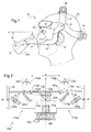
- a helmet-type support 10 for monitoring the eye movements of an individual comprises a helmet structure 12 designed to be fitted to the head of an individual 20, for example using elastic means (elastic band holding circling the head) or mechanical adjustment means 14.
- the helmet 10 further comprises two attachment arms 16 on either side of the face of the individual, rotatably mounted around the horizontal axis X with respect to the structure 12.
- the attachment arms 16 are bent and extend, diagonally, from the rotation points located at the height of the temporal zones of the individual towards the bottom of the face, firstly by a substantially vertical section, then by a horizontal section.
- the elbow 18 allows, as shown in the figure, to release the lateral field of view of the individual.
- an optical system 100 for monitoring the eye movements is arranged, articulated along the horizontal axis X ', an optical system 100 for monitoring the eye movements according to the invention.
- the optical system 100 has a main optical axis Z which, when the system is in use, is substantially aligned with the eyes 22 of the individual.
- the optical system 100 is rotatable about the X 'axis at an angular magnitude of about 10 °, relative to an initial position to align the Z optical axis of the system 100 with the eyes of the individual. This alignment makes it possible in particular to focus the image of the eyes on an image acquisition module provided in the optical system.
- the fixing arms 16 can, in turn, rotate about the X axis between a position where the main optical axis Z of the system 100 forms an angle ⁇ with a viewing plane ⁇ (here horizontal - plane formed by the eyes and a subject looked at) of the individual equal to 20 ° and a position where this angle is 35 °.
- a viewing plane ⁇ here horizontal - plane formed by the eyes and a subject looked at
- this angle is 35 °.
- the values of this angle are to be understood with the optical system 100 located below the viewing plane ⁇ . This freedom of rotation allows a vertical adjustment of the optical system 100 relative to the individual.
- This range of values [20 °, 45 °] makes it possible, in particular, to position the optical system 100 so that the field of view of the individual towards the bottom (angle ⁇ defined between the viewing plane ⁇ and the top of the system 100 ) has an angle ⁇ between 15 ° and 40 °. This angle of course depends on the dimensions of the optical system 100.
- angle ⁇ such that the angle ⁇ is between 18 ° and 30 °, and in particular equal to 20 °, optimizing the ratio between the angular aperture of the field of view downwards and the deformation of the images eyes.
- the length of the attachment arms 16 is designed so that the front face (the closest to the individual) of the optical system eye movement tracking is disposed at a distance d of the eyes, between 7 and 10 cm, and in particular equal to 8 cm.
- the eye movement tracking optical system 100 has the function of acquiring a sequence of images of the two eyes of the individual so that an analysis is performed to determine the behavior of the eyes (eye movements).
- the processing device (not shown) for carrying out this analysis may be embedded, in whole or in part, in the optical system 100. Preferably, however, in order to limit the complexity of the optical system 100, this processing device is predominantly external to the headphones 10.
- the data collected by the optical system 100 and transmitted to the external processing device may be of different types, including images or position data of each eye or velocity data, etc.
- transmission means are wired via a connector provided for this purpose at the level of the optical system 100 (192 on the figure 2 ), or by waves (for example wifi, bluetooth or equivalent), are provided to transmit the image data.
- the optical system 100 is thus connected to the processing device for tracking eye movements, which receives the image data. Since such transmission means, as well as the processing device, are widely known to those skilled in the art, they will not be described in more detail here and may take the form of one or more microcontrollers or processors.
- the acquisition performed here having the form of images
- the treatments performed to determine the ocular behavior of the individual are for example image analysis by detection of the eyes (or pupils) and by tracking the detected forms from image to image.
- the optical system 100 can be movably mounted using an attachment arm 16 to a fixed device on which is presented the face of the individual to be analyzed.
- the figure 2 illustrates in detail, in view from above, an embodiment of an optical system 100 according to the invention.
- the optical system 100 comprises two optical assemblies 110d and 110g respectively associated with the eyes of the individual, and arranged on the same support (not shown) of the system 100.
- the right eye 22d is presented opposite the entry zone 112d of the first optical assembly 110d, while the left eye 22g is presented opposite the entry zone 112g of the second optical assembly 110g.
- the placing in the eyes with the input areas is adjusted in particular through the rotation of the optical system 100 about the axis X '.
- the two optical assemblies 110d and 110g cooperate together to transmit the images of the eyes obtained at the input areas 112d and 112g to an acquisition module 190 and to bring them together when they emerge from these optical assemblies so that they are acquired simultaneously by the acquisition module 190, of the camera type such as CCD (" Charge-Coupled Device ") CMOS sensors (" Complementary metal oxide semi-conductor ”) well known to those skilled in the art . Simultaneity emerges from the fact that the images of each eye together reach the sensor (spatially juxtaposed). Thus, the acquisition at an instant t of an image by this sensor comprises the acquisition of the images of each eye.
- the two entry areas are opposite two non-contiguous areas of the face.
- the two images transmitted, each by one of the optical assemblies correspond to a discontinuous region of the individual's face.
- the input areas 112d and 112g are not necessarily materialized by openings (generally round) made in a housing of the optical system 100 and therefore define particular areas of the system with respect to the optical paths described below.
- the principle of the approximation of the images in this embodiment implements multiple reflections, in particular two reflections on flat mirrors.
- each eye 22d or 22g acquired traverses an optical path TOd or TOg which is composed of an input optical path 114d or 114g, an intermediate optical path 116d or 116g and an optical output path 118d or 118g.
- the input optical paths 114d and 114g are defined between the eyes 22d and 22g and a first plane mirror 120d or 120g in each set 110d and 110g.
- the optical input paths are preferably parallel to each other, and moreover parallel to the optical axis Z of the optical system 100.
- the intermediate optical paths 116d and 116g connect each first plane mirror 120d or 120g to a second plane mirror 122d or 122g, according to optical reflection principles.
- optical output paths 118d and 118g connect the second mirrors 122d and 122g and the camera 190.
- the arrangement of the mirrors shown here is such that the optical output paths are also parallel to each other and parallel to the optical axis Z. This results from the use of mirrors positioned at 45 ° with respect to each optical path, of such so that the light rays along these optical paths are reflected at 90 °.
- the invention however applies to other positioning of the mirrors, provided that the multiple reflections project the images of both eyes simultaneously on the camera 190.
- the angle of opening of the camera can vary slightly these optical paths.
- a camera of low focal length for example 8 mm
- a fine adjustment of the focus of the camera 190 is performed, to account for errors in the positioning of the mirrors in the optical system.
- the variations due to the variable shapes of the faces of individuals can lead to low blurs in the acquisition of the images of the eyes, without however hindering the effectiveness of the algorithms of pupil detection and / or eye movement tracking.
- the first mirrors 120d plans or 120g are located in front of both eyes 22d and 22g.
- the entrance areas are therefore the areas before these first mirrors.
- the first mirrors may in particular be formed of a gold-based reflective coating in order to obtain maximum reflectivity properties in the visible spectrum near the infrared and in the infrared, in particular a reflectivity coefficient of the order 96% in the 750-1500 nm area.
- a gold-based reflective coating in order to obtain maximum reflectivity properties in the visible spectrum near the infrared and in the infrared, in particular a reflectivity coefficient of the order 96% in the 750-1500 nm area.
- other less effective coatings aluminum or silver type metal coating
- each eye 22 is, in the example, reflected substantially at 90 ° by the first mirror 120 to be projected onto the second plane mirror 122 which is typically a triangular mirror whose two adjoining adjacent faces 122d and 122g, positioned at right angle, constitute the two second mirrors of optical assemblies 110d and 110g.
- these mirrors also have a reflective coating based on gold.
- Such a triangular mirror makes it possible to make the two images of the two eyes contiguous after their reflection on this mirror.
- the approximation of the images of each eye is a function of the distance of the two mirrors 122d and 122g or the distance from the "useful" area of these mirrors used for the reflection of the images of each eye.
- the two mirrors may be slightly distant to provide incomplete approximation of the images, or the "useful" areas may be offset from the adjacent edge 124, for example by shifting (along the Z axis towards the eyes) the first mirror 120 relative to the second mirror 122.
- the contiguous side 124 of the triangular mirror is placed in the optical axis (coinciding with the Z axis) of the camera 190.
- the two images of the contiguous eyes are detected equitably (each one half of the detection zone ) by the camera.
- the triangular mirror 122 makes it possible to return the image of each of the eyes to half of the sensor of the camera.
- the optical paths close to this Z axis follow, in the example of the figure 2 , reflections at right angles to such output that the corresponding optical paths 114d / 114g are parallel.
- the difference ⁇ between these parallel optical paths corresponds to the width of the zone of discontinuity between the eyes which is not acquired by the camera.
- this parallelism is all the more conserved as the camera 190 has a large opening angle. In this case the difference ⁇ is significantly increased.
- the projected length "l" of these mirrors on the window 140 protecting the optical system is a few centimeters, for example between 1.4 and 2 cm.
- this projected length "l" substantially delimiting what the camera 190 will acquire corresponds to a zone of the face around each eye which has a width "L” of the order of 5 to 7 cm (given the distance "d” of about 8 cm with the face).
- the optical system 100 according to the invention is tolerant to a variation of the inter-eye distance from one individual to another.
- this opening angle makes it possible to use second mirrors 122 of smaller dimensions than the first mirrors 120.
- the figure shows a camera disposed on the opposite side of the optical system 100 with respect to the eyes 22, it can be provided on the same side as the eyes by reversing the direction of the triangle mirror ( figure 4 ) Where additional mirrors 120 'and 120 "are provided to add multiple reflection.
- an infrared radiation diode 130d or 130g is provided in each optical assembly 110 to illuminate, in a direct manner, the corresponding eye.
- this infrared illumination makes it possible to improve the detection of the eyes in the images acquired by the camera 190, thanks to an enhancement of the contrast of the eye.
- this camera is inherently chosen as detecting in the wavelengths of the visible but also in the infrared corresponding to said diodes (generally a near-visible infrared, for example a diode at 830 nm).
- the infrared illumination by the diodes 130 can be of low intensity and continuously compared to known devices (higher intensity and pulsed illumination due to risks related to exposure of the eyes to illumination).
- the device according to the invention can therefore advantageously be used continuously longer on an individual, without risk to the eyes.
- a window 140 equips the optical system 100 at the entrance areas 112, between the eyes of the individual and the first mirrors 120.
- two panes can be used, each placed at a level of at least one window. entrance areas.
- window 140 physically protects the optical system 100 (incoming dust for example).
- the filter pane 140 is then chosen in particular to let the frequencies best detected by the camera 190 and / or the frequencies corresponding to the colors from which the subsequent treatments (detection of contours, pupils, etc.) are facilitated, especially the visible spectrum close to the infrared and the infrared from.
- the glass 140 may also be chosen polarizing, in order to eliminate or attenuate the reflections on the cornea of the eyes 22.
- the filtering and polarization means may be provided separately, for example using two superimposed panes.
- the invention makes it possible in particular to use a single camera filming each of the eyes independently.
- the camera is placed near the eyes, which avoids substantial optical distortion of the image of the eyes on the camera sensor and improves the pixel definition of the image acquired for each eye.
- FIG 5 illustrates the approximation of the independent images of each eye by comparison with the known prior art ( figure 5a ).
- This continuous zone 24 includes the areas relating to the two eyes 22d and 22g but also the zone 26 of the face located between the two eyes of the individual.
- two areas 24d and 24g of the face which are independent, non-contiguous and each centered on one of the two eyes, are acquired by the camera 190. As shown in the figure, these two areas correspond to a discontinuous region of the face of the individual and the system 100 projects this discontinuous region into a continuous image on the sensor of the camera 190.
- the optical system 100 avoids the acquisition of the zone 26 between the two eyes because it is not reflected by the first mirrors 120d and 120g.
- part of the zone 26 may be reflected by the first mirrors, but not transmitted to the acquisition module due for example to the absence of reflection by the second mirrors 122d and 122g.
- these second mirrors can be of reduced dimensions and arranged so as to reflect only a sub-part of what has been reflected by the first mirrors. This sub-part is then the zone 24d or 24g, according to the considered optical assembly.
- the non-transmission of the zone 26 results from the absence of reflection in part by the first mirrors and partly by the second mirrors.
- the optical system 100 thus allows the images (Im_d and Im_g) relating to the two zones 24d and 24g to be optically brought closer together so that they can be detected by the camera in close proximity. This approximation is made on all or part of the discontinuity between the two zones, that is to say on all or part of the zone 26 between the two eyes.
- “closely” means that the distance between the two eyes on the camera sensor is less than the distance between the two eyes on the face after transformation by the optical system (indeed the optical system can insert a slight modification distances even though the use of flat mirrors can limit this one).
- the two eyes on the image obtained by the invention are closer together than if they had been obtained by the same system by acquiring the entire area of the face including the area 26 between the eyes.
- the two detected images Im_d and Im_g are contiguous, thanks in particular to the use of contiguous mirrors 122d and 122g (triangle mirror).
- This optical approximation makes it possible to reduce the optical distance between the camera 190 and the eyes 22 with respect to the long distances required in a number of systems of the state of the art, so that the 'Im' image of the eyes presents a better definition for each eye. Indeed, the pixels traditionally used for the acquisition of the zone 26 between the two eyes are now allocated to the acquisition of Im_d and Im_g images of the zones 24d and 24g centered on the eyes.
- the optical system 100 can be positioned above this direction (15 ° to 40 ° ° upward viewing angle according to the rotation performed arms 16), but also on one side of the field of view of the individual, allowing according to the imposed constraints to clear a maximum field of view in preferred directions.
Landscapes
- Health & Medical Sciences (AREA)
- Life Sciences & Earth Sciences (AREA)
- Engineering & Computer Science (AREA)
- Heart & Thoracic Surgery (AREA)
- Molecular Biology (AREA)
- Biophysics (AREA)
- Veterinary Medicine (AREA)
- Biomedical Technology (AREA)
- Public Health (AREA)
- Medical Informatics (AREA)
- Physics & Mathematics (AREA)
- Surgery (AREA)
- Animal Behavior & Ethology (AREA)
- General Health & Medical Sciences (AREA)
- Human Computer Interaction (AREA)
- Ophthalmology & Optometry (AREA)
- Pathology (AREA)
- Eye Examination Apparatus (AREA)
Claims (12)
- Optisches System (100) zur Verfolgung okularer Bewegungen eines Gesichts eines Individuums (20), umfassend ein Modul (190) zur Bildaufnahme, das angeordnet ist, um ein Bild (lm) von zwei Augen (22, 22d, 22g) des Individuums zu erfassen, umfassend ein optisches Übertragungsmittel (110d, 110g) zum Erfassungsmodul (190) von zwei Bildern (lm_d, lm_g) von jeweils jedem Auge, die zusammen einer diskontinuierlichen Region (24d, 24g) des Gesichts entsprechen, durch mehrfache Reflexionen gemäß zweier optischer Verläufe (TOd, TOg), dadurch gekennzeichnet, dass die zwei optischen Verläufe ohne halbdurchlässige Spiegel sind,
und wobei die optischen Verläufe die optischen Eingangspfade (114d, 114g) in Bezug jeweils auf jedes Auge umfassen, die untereinander und zu einer optischen Achse (Z) des Bilderfassungsmoduls (190) parallel sind, und das optische Übertragungsmittel konfiguriert ist, um die zwei Bilder anzunähern, sodass das Erfassungsmodul (190) die zwei Bilder (lm_d, lm_g) gleichzeitig erfasst. - Optisches System (100) nach Anspruch 1, wobei das optische Übertragungsmittel (110d, 110g) die zwei Bilder durch mehrfache Reflexionen mittels ebener Spiegel (120, 122) annähert.
- Optisches System (100) nach Anspruch 1 oder 2, wobei das optische Übertragungsmittel zwei optische Einheiten (110d, 110g) umfasst, die jeweils über einen Eingangsbereich (112d, 112g) verfügen, die in Bezug auf jedes Auge (22d, 22g) anzubringen sind, und jede optische Einheit einen ersten Spiegel (120d, 120g) in Bezug auf den entsprechenden Eingangsbereich (112d, 112g) und einen zweiten Spiegel (122d, 122g) in Bezug auf die ersten Spiegel (112d, 112g) und das Bilderfassungsmodul (190) umfasst.
- Optisches System (100) nach Anspruch 3, wobei die zweiten Spiegel (122d, 122g) der zwei optischen Einheiten (110d, 110g) aneinandergrenzend sind.
- Optisches System (100) nach Anspruch 4, wobei der angrenzende Rand (124) der zweiten Spiegel (122d, 122g) im Wesentlichen in der optischen Achse (Z) des Bilderfassungsmoduls (190) angeordnet ist.
- Optisches System (100) nach einem der vorherigen Ansprüche, wobei die optischen Verläufe (TOd, TOg) optische Ausgangspfade (118d, 118g) umfassen, die auf das Bilderfassungsmodul (190) treffen, die untereinander und zu einer optischen Achse (Z) des Bilderfassungsmoduls parallel sind.
- Optisches System (100) nach einem der vorherigen Ansprüche, umfassend auf Ebene von zwei Eingangsbereichen (112d, 112g) des optischen Übertragungsmittels (1110d, 110g), die in Bezug auf jedes Auge (22d, 22g) anzubringen sind, ein Polarisationsmittel (140) von Lichtsignalen, die auf Ebene der Eingangsbereiche einfallen.
- Optisches System (100) nach einem der vorherigen Ansprüche, umfassend Mittel (130d, 130g) zur Infrarotbeleuchtung, die jeweils das eine von zwei Augen (22d, 22g) erhellen, wobei die Beleuchtungsmittel mit kontinuierlicher Abstrahlung funktionieren.
- Optisches System (100) nach einem der vorherigen Ansprüche, wobei das optische System (100) gelenkig an einem Befestigungsarm (16) montiert ist.
- Haltevorrichtung (10), die vorgesehen ist, um am Kopf eines Individuums (20) angebracht zu werden, dessen zwei Augen (22, 22d, 22g) ein Subjekt auf einer Sichtebene (Δ) betrachten, umfassend ein optisches System (100) zur Verfolgung okularer Bewegungen nach einem der vorherigen Ansprüche, und wobei eine optische Hauptachse (Z) des optischen Systems (100) einen Winkel (α) mit der Sichtebene (Δ) bildet.
- Vorrichtung (10) nach Anspruch 10, wobei der Winkel (α) zwischen der optischen Hauptachse (Z) und der Sichtebene (Δ) zwischen 20° und 45° beträgt, und das optische System unterhalb der Sichtebene (Δ) angebracht ist.
- Vorrichtung (10) nach Anspruch 10 oder 11, wobei das optische System (100) an einem Befestigungsarm (16) gelenkig in Bezug auf eine Trägerstruktur (12) montiert ist, um den Winkel (α) zwischen der optischen Hauptachse (Z) und der Sichtebene (Δ) zu variieren.
Applications Claiming Priority (2)
| Application Number | Priority Date | Filing Date | Title |
|---|---|---|---|
| FR1052720A FR2958528B1 (fr) | 2010-04-09 | 2010-04-09 | Systeme optique de suivi de mouvements oculaires et dispositif support associe |
| PCT/FR2011/050782 WO2011124852A1 (fr) | 2010-04-09 | 2011-04-07 | Systeme optique de suivi de mouvements oculaires et dispositif support associe |
Publications (2)
| Publication Number | Publication Date |
|---|---|
| EP2555667A1 EP2555667A1 (de) | 2013-02-13 |
| EP2555667B1 true EP2555667B1 (de) | 2016-10-12 |
Family
ID=42962451
Family Applications (1)
| Application Number | Title | Priority Date | Filing Date |
|---|---|---|---|
| EP11719340.9A Not-in-force EP2555667B1 (de) | 2010-04-09 | 2011-04-07 | Optisches system zur verfolgung der augenbewegung und zugehörige trägervorrichtung |
Country Status (4)
| Country | Link |
|---|---|
| US (1) | US9089286B2 (de) |
| EP (1) | EP2555667B1 (de) |
| FR (1) | FR2958528B1 (de) |
| WO (1) | WO2011124852A1 (de) |
Families Citing this family (6)
| Publication number | Priority date | Publication date | Assignee | Title |
|---|---|---|---|---|
| ITVR20110201A1 (it) | 2011-11-02 | 2013-05-03 | Milano Politecnico | Dispositivo per il monitoraggio della posizione e deimovimenti dell'occhio, particolarmente adatto per la radioterapia oculare |
| US9727991B2 (en) * | 2013-03-01 | 2017-08-08 | Microsoft Technology Licensing, Llc | Foveated image rendering |
| EP3117263B1 (de) * | 2014-03-14 | 2018-05-09 | Sony Interactive Entertainment Inc. | Verfahren und systeme zur verfolgung einer kopfmontierten anzeige sowie kalibrierungen für anpassungen der kopfmontierten anzeige |
| EP3241488A1 (de) | 2016-05-06 | 2017-11-08 | Aura Innovative Robotics, S.L | Vorrichtung zur synchronisierten messung von okularer und kephalischer bewegung |
| WO2025051943A1 (en) | 2023-09-08 | 2025-03-13 | Aura Innovative Robotics, S.L. | Device and method for obtaining dynamic measurements of eye optical surfaces |
| FR3153981B1 (fr) | 2023-10-12 | 2026-01-02 | Sierra | Dispositif d’acquisition de données oculaires et ensemble pour l’acquisition de données oculaires |
Family Cites Families (31)
| Publication number | Priority date | Publication date | Assignee | Title |
|---|---|---|---|---|
| US4102564A (en) * | 1975-04-18 | 1978-07-25 | Michael Henry L | Portable device for the accurate measurement of eye movements both in light and obscurity |
| JPS6092730A (ja) * | 1983-10-26 | 1985-05-24 | 株式会社トプコン | 眼位検査装置 |
| US4838678A (en) * | 1986-12-10 | 1989-06-13 | Lyons Eye Institute Of Western Australian Incorporated | Magnifying binocular ophthalmoscope |
| US4852988A (en) * | 1988-09-12 | 1989-08-01 | Applied Science Laboratories | Visor and camera providing a parallax-free field-of-view image for a head-mounted eye movement measurement system |
| US5150137A (en) * | 1990-10-10 | 1992-09-22 | Pulse Medical Instruments | Positioning system for pupil imaging optics |
| JPH074343B2 (ja) * | 1992-09-29 | 1995-01-25 | 株式会社エイ・ティ・アール視聴覚機構研究所 | 奥行き知覚分析装置 |
| US5714967A (en) * | 1994-05-16 | 1998-02-03 | Olympus Optical Co., Ltd. | Head-mounted or face-mounted image display apparatus with an increased exit pupil |
| DE4417762C1 (de) * | 1994-05-20 | 1995-10-12 | Juergen Prof Dr Med Lamprecht | Vorrichtung und Verfahren zum Projizieren und Empfangen von Bildinformation mittels eines Bildschirms |
| US6003991A (en) * | 1996-02-17 | 1999-12-21 | Erik Scott Viirre | Eye examination apparatus and method for remote examination of a patient by a health professional |
| US6089716A (en) * | 1996-07-29 | 2000-07-18 | Lashkari; Kameran | Electro-optic binocular indirect ophthalmoscope for stereoscopic observation of retina |
| US6386706B1 (en) * | 1996-07-31 | 2002-05-14 | Virtual-Eye.Com | Visual function testing with virtual retinal display |
| DE19704197A1 (de) * | 1997-02-05 | 1998-08-06 | Zeiss Carl Jena Gmbh | Anordnung zur subjektivem Refraktionsbestimmung und/oder zur Bestimmung anderer Sehfunktionen |
| US5867587A (en) * | 1997-05-19 | 1999-02-02 | Northrop Grumman Corporation | Impaired operator detection and warning system employing eyeblink analysis |
| US5963300A (en) * | 1998-02-17 | 1999-10-05 | Amt Technologies, Corp. | Ocular biometer |
| CA2298515A1 (en) * | 1999-02-11 | 2001-08-10 | Queen's University At Kingston | Method and apparatus for detecting eye movement |
| US6120461A (en) * | 1999-08-09 | 2000-09-19 | The United States Of America As Represented By The Secretary Of The Army | Apparatus for tracking the human eye with a retinal scanning display, and method thereof |
| JP2003050356A (ja) * | 2001-08-07 | 2003-02-21 | Olympus Optical Co Ltd | 手術用顕微鏡 |
| US6943754B2 (en) | 2002-09-27 | 2005-09-13 | The Boeing Company | Gaze tracking system, eye-tracking assembly and an associated method of calibration |
| US7731360B2 (en) * | 2003-11-07 | 2010-06-08 | Neuro Kinetics | Portable video oculography system |
| US20110077548A1 (en) * | 2004-04-01 | 2011-03-31 | Torch William C | Biosensors, communicators, and controllers monitoring eye movement and methods for using them |
| US20060210111A1 (en) * | 2005-03-16 | 2006-09-21 | Dixon Cleveland | Systems and methods for eye-operated three-dimensional object location |
| ES2264383B1 (es) * | 2005-06-03 | 2007-11-16 | Hospital Sant Joan De Deu | Dispositivo captador de movimientos oculares. |
| US7338166B2 (en) * | 2006-04-05 | 2008-03-04 | Acunetx, Inc. | Image-based system to observe and document eye responses having a reflective protractor for measurement of stimulus position |
| US8016420B2 (en) * | 2007-05-17 | 2011-09-13 | Amo Development Llc. | System and method for illumination and fixation with ophthalmic diagnostic instruments |
| US8457352B2 (en) * | 2007-05-23 | 2013-06-04 | The University Of British Columbia | Methods and apparatus for estimating point-of-gaze in three dimensions |
| ITRM20070526A1 (it) * | 2007-10-05 | 2009-04-06 | Univ Roma | Apparato di acquisizione ed elaborazione delle informazioni relative ad attivita oculari umane |
| US7810928B2 (en) * | 2008-02-26 | 2010-10-12 | Konan Medical Usa, Inc. | Evaluating pupillary responses to light stimuli |
| JP2009240551A (ja) * | 2008-03-31 | 2009-10-22 | Panasonic Corp | 視線検出装置 |
| US20110085135A1 (en) * | 2008-08-11 | 2011-04-14 | Eugene Robert Bertolli | Free space hands free ocular observation camera mount |
| HU0900696D0 (en) * | 2009-11-05 | 2009-12-28 | Holakovszky Laszlo | Binocular display device |
| JP5613025B2 (ja) * | 2009-11-18 | 2014-10-22 | パナソニック株式会社 | 視線検出装置、視線検出方法、眼電位計測装置、ウェアラブルカメラ、ヘッドマウントディスプレイ、電子めがねおよび眼科診断装置 |
-
2010
- 2010-04-09 FR FR1052720A patent/FR2958528B1/fr not_active Expired - Fee Related
-
2011
- 2011-04-07 EP EP11719340.9A patent/EP2555667B1/de not_active Not-in-force
- 2011-04-07 US US13/639,121 patent/US9089286B2/en not_active Expired - Fee Related
- 2011-04-07 WO PCT/FR2011/050782 patent/WO2011124852A1/fr not_active Ceased
Also Published As
| Publication number | Publication date |
|---|---|
| US20130027665A1 (en) | 2013-01-31 |
| EP2555667A1 (de) | 2013-02-13 |
| FR2958528B1 (fr) | 2015-12-18 |
| US9089286B2 (en) | 2015-07-28 |
| WO2011124852A1 (fr) | 2011-10-13 |
| FR2958528A1 (fr) | 2011-10-14 |
Similar Documents
| Publication | Publication Date | Title |
|---|---|---|
| EP2555667B1 (de) | Optisches system zur verfolgung der augenbewegung und zugehörige trägervorrichtung | |
| EP1989582B1 (de) | Verfahren und einrichtung zum identifizieren und kalibrieren panoramischer optischer systeme | |
| EP2901209B1 (de) | Verfahren zur bestimmung der sichtparameter einer person | |
| EP3627210B1 (de) | Virtual-reality- oder augmented-reality-sichtsystem mit bildsensor des auges, und entsprechendes verfahren | |
| WO2007020334A1 (fr) | Methode et systeme de correction des aberrations de l'œil pour instrument ophtalmique | |
| EP2098072B1 (de) | Vorrichtung für eine videokonferenz-kommunikation und entsprechendes kommunikationsverfahren | |
| CA2701151A1 (fr) | Systeme d'imagerie a modification de front d'onde et procede d'augmentation de la profondeur de champ d'un systeme d'imagerie | |
| EP2677920B1 (de) | Verfahren und vorrichtung für hochauflösende retinabildgebung | |
| WO2018019808A1 (fr) | Systèmes et procédés d'imagerie interférentielle plein champ | |
| EP3982188B1 (de) | Virtual-reality- oder augmented-reality-sichtsystem mit bildsensor des auges | |
| FR2558959A1 (fr) | Appareil de controle de surfaces d'objets | |
| WO1988006859A1 (fr) | Dispositif d'observation de l'oeil utilisant la reflexion d'un rayonnement infrarouge par le globe oculaire | |
| EP3478151B1 (de) | Augenmessvorrichtung mit einem auf die blickrichtung des benutzers optisch ausgerichteten system | |
| FR2866551A1 (fr) | Methode et systeme de correction des aberrations de l'oeil pour un instrument ophtalmique | |
| EP1763695B1 (de) | Ophthalmische anzeige mit vorrichtung zur anpassung an den pupillenabstand des benutzers | |
| FR3153981A1 (fr) | Dispositif d’acquisition de données oculaires et ensemble pour l’acquisition de données oculaires | |
| FR3070497B1 (fr) | Instrument d'imagerie pour controler une designation de cible | |
| FR3155065A1 (fr) | Procédé d'imagerie par tomographie par cohérence optique plein champ, FFOCT, avec réglage d'alignement | |
| FR2924821A1 (fr) | Systeme d'imagerie. | |
| WO2015075177A1 (fr) | Dispositif d'observation visuelle, en particulier, pour une application dermatologique |
Legal Events
| Date | Code | Title | Description |
|---|---|---|---|
| PUAI | Public reference made under article 153(3) epc to a published international application that has entered the european phase |
Free format text: ORIGINAL CODE: 0009012 |
|
| 17P | Request for examination filed |
Effective date: 20121003 |
|
| AK | Designated contracting states |
Kind code of ref document: A1 Designated state(s): AL AT BE BG CH CY CZ DE DK EE ES FI FR GB GR HR HU IE IS IT LI LT LU LV MC MK MT NL NO PL PT RO RS SE SI SK SM TR |
|
| DAX | Request for extension of the european patent (deleted) | ||
| REG | Reference to a national code |
Ref country code: DE Ref legal event code: R079 Ref document number: 602011031182 Country of ref document: DE Free format text: PREVIOUS MAIN CLASS: A61B0003113000 Ipc: A61B0005000000 |
|
| GRAP | Despatch of communication of intention to grant a patent |
Free format text: ORIGINAL CODE: EPIDOSNIGR1 |
|
| RAP1 | Party data changed (applicant data changed or rights of an application transferred) |
Owner name: SURICOG |
|
| RIC1 | Information provided on ipc code assigned before grant |
Ipc: A61B 3/113 20060101ALI20160502BHEP Ipc: A61B 5/00 20060101AFI20160502BHEP |
|
| INTG | Intention to grant announced |
Effective date: 20160601 |
|
| RIN1 | Information on inventor provided before grant (corrected) |
Inventor name: MAILLARD, MICKAEL Inventor name: KINKINGNEHUN, SERGE Inventor name: BERNERT, FREDERIC |
|
| GRAS | Grant fee paid |
Free format text: ORIGINAL CODE: EPIDOSNIGR3 |
|
| GRAA | (expected) grant |
Free format text: ORIGINAL CODE: 0009210 |
|
| AK | Designated contracting states |
Kind code of ref document: B1 Designated state(s): AL AT BE BG CH CY CZ DE DK EE ES FI FR GB GR HR HU IE IS IT LI LT LU LV MC MK MT NL NO PL PT RO RS SE SI SK SM TR |
|
| REG | Reference to a national code |
Ref country code: GB Ref legal event code: FG4D Free format text: NOT ENGLISH |
|
| REG | Reference to a national code |
Ref country code: CH Ref legal event code: EP |
|
| REG | Reference to a national code |
Ref country code: AT Ref legal event code: REF Ref document number: 835702 Country of ref document: AT Kind code of ref document: T Effective date: 20161015 |
|
| REG | Reference to a national code |
Ref country code: IE Ref legal event code: FG4D Free format text: LANGUAGE OF EP DOCUMENT: FRENCH |
|
| REG | Reference to a national code |
Ref country code: DE Ref legal event code: R096 Ref document number: 602011031182 Country of ref document: DE |
|
| REG | Reference to a national code |
Ref country code: LT Ref legal event code: MG4D |
|
| REG | Reference to a national code |
Ref country code: NL Ref legal event code: MP Effective date: 20161012 |
|
| REG | Reference to a national code |
Ref country code: FR Ref legal event code: PLFP Year of fee payment: 7 |
|
| PG25 | Lapsed in a contracting state [announced via postgrant information from national office to epo] |
Ref country code: LV Free format text: LAPSE BECAUSE OF FAILURE TO SUBMIT A TRANSLATION OF THE DESCRIPTION OR TO PAY THE FEE WITHIN THE PRESCRIBED TIME-LIMIT Effective date: 20161012 |
|
| REG | Reference to a national code |
Ref country code: AT Ref legal event code: MK05 Ref document number: 835702 Country of ref document: AT Kind code of ref document: T Effective date: 20161012 |
|
| PG25 | Lapsed in a contracting state [announced via postgrant information from national office to epo] |
Ref country code: NO Free format text: LAPSE BECAUSE OF FAILURE TO SUBMIT A TRANSLATION OF THE DESCRIPTION OR TO PAY THE FEE WITHIN THE PRESCRIBED TIME-LIMIT Effective date: 20170112 Ref country code: GR Free format text: LAPSE BECAUSE OF FAILURE TO SUBMIT A TRANSLATION OF THE DESCRIPTION OR TO PAY THE FEE WITHIN THE PRESCRIBED TIME-LIMIT Effective date: 20170113 Ref country code: SE Free format text: LAPSE BECAUSE OF FAILURE TO SUBMIT A TRANSLATION OF THE DESCRIPTION OR TO PAY THE FEE WITHIN THE PRESCRIBED TIME-LIMIT Effective date: 20161012 Ref country code: LT Free format text: LAPSE BECAUSE OF FAILURE TO SUBMIT A TRANSLATION OF THE DESCRIPTION OR TO PAY THE FEE WITHIN THE PRESCRIBED TIME-LIMIT Effective date: 20161012 |
|
| PG25 | Lapsed in a contracting state [announced via postgrant information from national office to epo] |
Ref country code: HR Free format text: LAPSE BECAUSE OF FAILURE TO SUBMIT A TRANSLATION OF THE DESCRIPTION OR TO PAY THE FEE WITHIN THE PRESCRIBED TIME-LIMIT Effective date: 20161012 Ref country code: IS Free format text: LAPSE BECAUSE OF FAILURE TO SUBMIT A TRANSLATION OF THE DESCRIPTION OR TO PAY THE FEE WITHIN THE PRESCRIBED TIME-LIMIT Effective date: 20170212 Ref country code: FI Free format text: LAPSE BECAUSE OF FAILURE TO SUBMIT A TRANSLATION OF THE DESCRIPTION OR TO PAY THE FEE WITHIN THE PRESCRIBED TIME-LIMIT Effective date: 20161012 Ref country code: RS Free format text: LAPSE BECAUSE OF FAILURE TO SUBMIT A TRANSLATION OF THE DESCRIPTION OR TO PAY THE FEE WITHIN THE PRESCRIBED TIME-LIMIT Effective date: 20161012 Ref country code: ES Free format text: LAPSE BECAUSE OF FAILURE TO SUBMIT A TRANSLATION OF THE DESCRIPTION OR TO PAY THE FEE WITHIN THE PRESCRIBED TIME-LIMIT Effective date: 20161012 Ref country code: PL Free format text: LAPSE BECAUSE OF FAILURE TO SUBMIT A TRANSLATION OF THE DESCRIPTION OR TO PAY THE FEE WITHIN THE PRESCRIBED TIME-LIMIT Effective date: 20161012 Ref country code: AT Free format text: LAPSE BECAUSE OF FAILURE TO SUBMIT A TRANSLATION OF THE DESCRIPTION OR TO PAY THE FEE WITHIN THE PRESCRIBED TIME-LIMIT Effective date: 20161012 Ref country code: PT Free format text: LAPSE BECAUSE OF FAILURE TO SUBMIT A TRANSLATION OF THE DESCRIPTION OR TO PAY THE FEE WITHIN THE PRESCRIBED TIME-LIMIT Effective date: 20170213 Ref country code: NL Free format text: LAPSE BECAUSE OF FAILURE TO SUBMIT A TRANSLATION OF THE DESCRIPTION OR TO PAY THE FEE WITHIN THE PRESCRIBED TIME-LIMIT Effective date: 20161012 |
|
| REG | Reference to a national code |
Ref country code: DE Ref legal event code: R097 Ref document number: 602011031182 Country of ref document: DE |
|
| PG25 | Lapsed in a contracting state [announced via postgrant information from national office to epo] |
Ref country code: CZ Free format text: LAPSE BECAUSE OF FAILURE TO SUBMIT A TRANSLATION OF THE DESCRIPTION OR TO PAY THE FEE WITHIN THE PRESCRIBED TIME-LIMIT Effective date: 20161012 Ref country code: EE Free format text: LAPSE BECAUSE OF FAILURE TO SUBMIT A TRANSLATION OF THE DESCRIPTION OR TO PAY THE FEE WITHIN THE PRESCRIBED TIME-LIMIT Effective date: 20161012 Ref country code: DK Free format text: LAPSE BECAUSE OF FAILURE TO SUBMIT A TRANSLATION OF THE DESCRIPTION OR TO PAY THE FEE WITHIN THE PRESCRIBED TIME-LIMIT Effective date: 20161012 Ref country code: SK Free format text: LAPSE BECAUSE OF FAILURE TO SUBMIT A TRANSLATION OF THE DESCRIPTION OR TO PAY THE FEE WITHIN THE PRESCRIBED TIME-LIMIT Effective date: 20161012 Ref country code: RO Free format text: LAPSE BECAUSE OF FAILURE TO SUBMIT A TRANSLATION OF THE DESCRIPTION OR TO PAY THE FEE WITHIN THE PRESCRIBED TIME-LIMIT Effective date: 20161012 |
|
| PLBE | No opposition filed within time limit |
Free format text: ORIGINAL CODE: 0009261 |
|
| STAA | Information on the status of an ep patent application or granted ep patent |
Free format text: STATUS: NO OPPOSITION FILED WITHIN TIME LIMIT |
|
| PG25 | Lapsed in a contracting state [announced via postgrant information from national office to epo] |
Ref country code: BG Free format text: LAPSE BECAUSE OF FAILURE TO SUBMIT A TRANSLATION OF THE DESCRIPTION OR TO PAY THE FEE WITHIN THE PRESCRIBED TIME-LIMIT Effective date: 20170112 Ref country code: SM Free format text: LAPSE BECAUSE OF FAILURE TO SUBMIT A TRANSLATION OF THE DESCRIPTION OR TO PAY THE FEE WITHIN THE PRESCRIBED TIME-LIMIT Effective date: 20161012 Ref country code: IT Free format text: LAPSE BECAUSE OF FAILURE TO SUBMIT A TRANSLATION OF THE DESCRIPTION OR TO PAY THE FEE WITHIN THE PRESCRIBED TIME-LIMIT Effective date: 20161012 |
|
| 26N | No opposition filed |
Effective date: 20170713 |
|
| PG25 | Lapsed in a contracting state [announced via postgrant information from national office to epo] |
Ref country code: SI Free format text: LAPSE BECAUSE OF FAILURE TO SUBMIT A TRANSLATION OF THE DESCRIPTION OR TO PAY THE FEE WITHIN THE PRESCRIBED TIME-LIMIT Effective date: 20161012 |
|
| REG | Reference to a national code |
Ref country code: CH Ref legal event code: PL |
|
| REG | Reference to a national code |
Ref country code: IE Ref legal event code: MM4A |
|
| PG25 | Lapsed in a contracting state [announced via postgrant information from national office to epo] |
Ref country code: MC Free format text: LAPSE BECAUSE OF FAILURE TO SUBMIT A TRANSLATION OF THE DESCRIPTION OR TO PAY THE FEE WITHIN THE PRESCRIBED TIME-LIMIT Effective date: 20161012 |
|
| PG25 | Lapsed in a contracting state [announced via postgrant information from national office to epo] |
Ref country code: LI Free format text: LAPSE BECAUSE OF NON-PAYMENT OF DUE FEES Effective date: 20170430 Ref country code: CH Free format text: LAPSE BECAUSE OF NON-PAYMENT OF DUE FEES Effective date: 20170430 Ref country code: LU Free format text: LAPSE BECAUSE OF NON-PAYMENT OF DUE FEES Effective date: 20170407 |
|
| REG | Reference to a national code |
Ref country code: BE Ref legal event code: MM Effective date: 20170430 |
|
| REG | Reference to a national code |
Ref country code: FR Ref legal event code: PLFP Year of fee payment: 8 |
|
| PG25 | Lapsed in a contracting state [announced via postgrant information from national office to epo] |
Ref country code: IE Free format text: LAPSE BECAUSE OF NON-PAYMENT OF DUE FEES Effective date: 20170407 |
|
| PG25 | Lapsed in a contracting state [announced via postgrant information from national office to epo] |
Ref country code: BE Free format text: LAPSE BECAUSE OF NON-PAYMENT OF DUE FEES Effective date: 20170430 |
|
| PG25 | Lapsed in a contracting state [announced via postgrant information from national office to epo] |
Ref country code: MT Free format text: LAPSE BECAUSE OF FAILURE TO SUBMIT A TRANSLATION OF THE DESCRIPTION OR TO PAY THE FEE WITHIN THE PRESCRIBED TIME-LIMIT Effective date: 20161012 |
|
| PG25 | Lapsed in a contracting state [announced via postgrant information from national office to epo] |
Ref country code: HU Free format text: LAPSE BECAUSE OF FAILURE TO SUBMIT A TRANSLATION OF THE DESCRIPTION OR TO PAY THE FEE WITHIN THE PRESCRIBED TIME-LIMIT; INVALID AB INITIO Effective date: 20110407 |
|
| PG25 | Lapsed in a contracting state [announced via postgrant information from national office to epo] |
Ref country code: CY Free format text: LAPSE BECAUSE OF NON-PAYMENT OF DUE FEES Effective date: 20161012 |
|
| PG25 | Lapsed in a contracting state [announced via postgrant information from national office to epo] |
Ref country code: MK Free format text: LAPSE BECAUSE OF FAILURE TO SUBMIT A TRANSLATION OF THE DESCRIPTION OR TO PAY THE FEE WITHIN THE PRESCRIBED TIME-LIMIT Effective date: 20161012 |
|
| PG25 | Lapsed in a contracting state [announced via postgrant information from national office to epo] |
Ref country code: TR Free format text: LAPSE BECAUSE OF FAILURE TO SUBMIT A TRANSLATION OF THE DESCRIPTION OR TO PAY THE FEE WITHIN THE PRESCRIBED TIME-LIMIT Effective date: 20161012 |
|
| PG25 | Lapsed in a contracting state [announced via postgrant information from national office to epo] |
Ref country code: AL Free format text: LAPSE BECAUSE OF FAILURE TO SUBMIT A TRANSLATION OF THE DESCRIPTION OR TO PAY THE FEE WITHIN THE PRESCRIBED TIME-LIMIT Effective date: 20161012 |
|
| PGFP | Annual fee paid to national office [announced via postgrant information from national office to epo] |
Ref country code: GB Payment date: 20220323 Year of fee payment: 12 |
|
| PGFP | Annual fee paid to national office [announced via postgrant information from national office to epo] |
Ref country code: FR Payment date: 20220329 Year of fee payment: 12 |
|
| PGFP | Annual fee paid to national office [announced via postgrant information from national office to epo] |
Ref country code: DE Payment date: 20220322 Year of fee payment: 12 |
|
| REG | Reference to a national code |
Ref country code: DE Ref legal event code: R119 Ref document number: 602011031182 Country of ref document: DE |
|
| GBPC | Gb: european patent ceased through non-payment of renewal fee |
Effective date: 20230407 |
|
| PG25 | Lapsed in a contracting state [announced via postgrant information from national office to epo] |
Ref country code: GB Free format text: LAPSE BECAUSE OF NON-PAYMENT OF DUE FEES Effective date: 20230407 |
|
| PG25 | Lapsed in a contracting state [announced via postgrant information from national office to epo] |
Ref country code: GB Free format text: LAPSE BECAUSE OF NON-PAYMENT OF DUE FEES Effective date: 20230407 Ref country code: FR Free format text: LAPSE BECAUSE OF NON-PAYMENT OF DUE FEES Effective date: 20230430 Ref country code: DE Free format text: LAPSE BECAUSE OF NON-PAYMENT OF DUE FEES Effective date: 20231103 |